

Product images are for informational purposes only and may vary slightly depending on the batch and supplier. Product specifications and prices may be subject to change without notice. We do our best to provide accurate and complete product specifications, but they may not be completely accurate. If you encounter any such situation, please let us know.
The product is intended for specialists and requires qualified and authorized personnel. The product does not include assembly/use instructions . Putting the product into operation by unqualified persons leads to the loss of the warranty according to the Terms and Conditions on the site.
The specified technical parameters (current, power, etc.) represent maximum allowable values under ideal operating conditions. For safe use and optimal lifespan, it is recommended to operate the product continuously at no more than 50% of the specified maximum values.
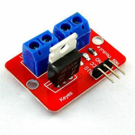
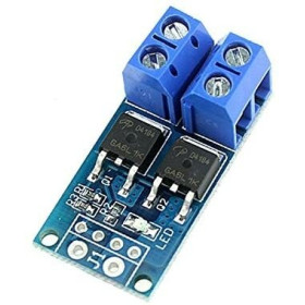
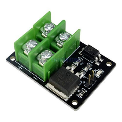
MOSFET E-Switch module, 3–20V control, 5–36V output, with optocoupler
Switches and regulates LED strips, DC motors and other loads via PWM, controlled by Arduino or microcontrollers. It has opto-isolator for power control separation, 3-12V input and 5-36V output, supports up to 22A with active cooling, 2.54mm DuPont compatible pins for quick connection.
Buying this product earns you 1.03 RON in loyalty points.

International fast shipping within EU. Free Shipping for orders above 100 EUR in most EU countries.

We ship from our stock within 24H

You earn points with every order, worth 5%.
The electronic switch module with F5305S MOSFET and optocoupler allows switching on, switching off, and PWM control of 5 - 36 VDC DC loads, using a 3 - 20 VDC logic signal from a microcontroller, development board, or another signal source. It is suitable for LED strips, light bulbs, DC motors, small pumps, solenoid valves, and other DC-powered equipment where a mechanical relay would be too slow, noisy, or would not allow PWM control.
Switching is performed by the P-channel F5305S MOSFET in a D2PAK package, mounted on the positive line of the load, so the consumer’s negative terminal remains directly connected to the source negative. The control circuit is optically isolated from the power circuit by the PC817 optocoupler, so the logic ground and load ground do not need to be connected. The control current is approximately 5 mA. The module supports PWM signals, so the brightness of an LED strip or the speed of a DC motor can be adjusted. Without a heatsink the module switches up to 5 A, and with a heatsink and fan the maximum current reaches 22 A.
Among the main features are two green screw terminal blocks marked + and -, each with two screws, the IN+ and IN- control pins with 2.54 mm pitch, compatible with DuPont connectors, the arrow on the board indicating the direction of connection of the load, and four mounting holes. The module does not have a separate power input. The control side is powered from the signal applied to IN+ and IN-, while the load receives voltage from the 5 - 36 VDC source connected to the terminal block.
Through the logic control input, the module is compatible with Arduino, ESP32, STM32, Raspberry Pi, and other boards or circuits that provide 3.3 V or 5 V digital or PWM outputs.

Specifications:
Controlled voltage: 5 - 36 VDC
Maximum current without heatsink: 5 A
Maximum current with active cooling: 22 A (heatsink and fan, the module must not overheat)
Control voltage (logic): 3 - 20 VDC
Control current: approximately 5 mA
Transistor: P-channel MOSFET F5305S, D2PAK package
Optocoupler: PC817
Isolation: Optical, logic voltage and controlled voltage are separated by the optocoupler
Control signal: Digital (on/off) or PWM
Control connector: 2 pins, 2.54 mm pitch (IN+ / IN-)
Power connector: 2 screw terminal blocks (+ / -)
Dimensions: 42 x 26 mm
Layout:
| Element | Function |
|---|---|
| + terminal block | Two screws for the positive line. One screw receives the source positive, and the other is the output to the load positive. The arrow on the board shows the direction from source to load. |
| - terminal block | Two screws for the common negative. The source negative and the load negative are connected here. |
| Arrow on the board | Indicates the direction of connection of the load, i.e. the direction of voltage flow from source to load. |
| MOSFET F5305S | P-channel transistor in D2PAK package that switches the positive line of the load. It heats up at high currents, so above 5 A it requires a heatsink and fan. |
| PC817 optocoupler | Optically isolates the control circuit from the power circuit. |
| IN+ / IN- control pins | Control signal input, with 2.54 mm pitch. IN+ has a square pad, and IN- a round pad, both marked on the back of the board. |
| R1 - R3 SMD resistors | Bias components for the control circuit and the MOSFET gate. |
| D1 SMD LED | Indicator located near the control pins, on the control circuit, which lights when the control signal is present. |
| Mounting holes | Four holes for fastening the board. |
Pinout:
| Connector | Pin | Function |
|---|---|---|
| Control (2.54 mm) | IN+ | Positive input of the control signal, 3 - 20 VDC, digital or PWM |
| Control (2.54 mm) | IN- | Reference of the control signal (logic ground) |
| + terminal block | + (screw from the tail of the arrow) | Source positive input, 5 - 36 VDC |
| + terminal block | + (screw from the tip of the arrow) | Switched output to the load positive |
| - terminal block | - (first screw) | Source negative |
| - terminal block | - (second screw) | Load negative (common negative with the source) |
Usage:
Connect the IN+ pin to the digital or PWM output of the control board and the IN- pin to its ground, using wires with DuPont connectors.
Do not apply a control voltage higher than 20 VDC to IN+ and IN-, and observe polarity, with IN+ being the pin with the square pad.
Connect the positive of the power supply to the screw of the + terminal block located at the tail of the arrow on the board, and the positive of the load to the screw of the + block located at the tip of the arrow.
Connect the negative of the power supply and the negative of the load to the two screws of the - terminal block.
Use a 5 - 36 VDC power supply, observe polarity, and do not exceed 36 VDC. Reversing the source and the load relative to the direction of the arrow can leave the load permanently powered.
Power the supply only after you have finished all connections. When control voltage appears on IN+, the load turns on, and when it disappears it turns off. The LED near the control pins indicates the presence of the signal.
For adjustment, apply a PWM signal to IN+. The higher the duty cycle, the brighter the LED strip lights or the faster the motor rotates.
For inductive loads such as DC motors, solenoid valves, or pumps, install a protection diode, for example 1N5819 or 1N4007, in parallel with the load, with the cathode toward positive.
For currents up to 5 A the module does not require cooling. Above 5 A, mount a heatsink and fan on the MOSFET, use wires with appropriate cross-section, and verify that the module does not overheat.
The ground of the control board must not be connected to the negative of the power supply, because the two circuits are optically isolated.
For stable results, tighten the terminal block screws well and keep the space around the MOSFET clear for cooling.
- Dimensions
- 42 x 26 mm
- Output voltage
- 5-36 V DC
- Maximum current
- 5 A (without heatsink), 22 A (with active cooling)
- Logic voltage
- 3-20 V DC
- Connector type
- 2 pins, 2.54 mm pitch (IN+ / IN-)
- Current
- aproximativ 5 mA
- Integrated circuit
- P-channel MOSFET F5305S
- Package
- D2PAK
- Insulation
- optical
Produs destinat utilizarii in proiecte electronice, automatizari, prototipare, educatie si cercetare.
Produsul trebuie utilizat numai conform specificatiilor tehnice mentionate in descriere si/sau in documentatia produsului.
Avertismente generale de siguranta:
Nu utilizati produsul la tensiuni, curenti sau temperaturi peste valorile specificate.
Montajul si conectarea trebuie realizate de persoane cu cunostinte tehnice minime in domeniul electric/electronic.
Evitati scurtcircuitele, inversarea polaritatii si conectarea gresita a alimentarii.
Nu lasati produsul alimentat nesupravegheat in timpul testelor.
Produsul nu este jucarie si nu este destinat copiilor.
Pentru modulele electronice, se recomanda utilizarea in carcase, panouri sau montaje protejate, dupa caz.
Identificare produs:
Denumirea produsului, codul/SKU-ul si caracteristicile tehnice sunt mentionate in pagina produsului si/sau pe eticheta ambalajului.
Producator / Importator / Distribuitor:
Sigmanortec S.R.L.
Calea Bucuresti nr. 9, Targu Jiu, Gorj, Romania
E-mail: [email protected]
Website: www.sigmanortec.ro
Persoana responsabila in UE:
Sigmanortec S.R.L.
Calea Bucuresti nr. 9, Targu Jiu, Gorj, Romania
E-mail: [email protected]
Documentatie si siguranta:
Pentru informatii suplimentare, fise tehnice, declaratii de conformitate sau instructiuni, ne puteti contacta la [email protected].
/*
  E-Switch MOSFET module with optoisolator (F5305S + PC817) - test

  Board: Arduino Uno (Tools > Board > Arduino AVR Boards > Arduino Uno)
  Libraries: none needed.

  Wiring:
    Module IN+  -> Arduino Uno D9 (PWM)
    Module IN-  -> Arduino Uno GND
    Module + (screw 1) -> DC supply + (5 - 36 V)
    Module - (screw 1) -> DC supply -
    Module + (screw 2) -> load +
    Module - (screw 2) -> load -
  The arrow on the board points from the supply to the load.
*/

const int MOSFET_PIN = 9;   // control pin connected to IN+

void setup() {
  Serial.begin(9600);
  pinMode(MOSFET_PIN, OUTPUT);
  Serial.println("MOSFET module test started");
}

void loop() {
  // Full on
  digitalWrite(MOSFET_PIN, HIGH);
  Serial.println("Load ON (100 %)");
  delay(2000);

  // Half power with PWM
  analogWrite(MOSFET_PIN, 128);
  Serial.println("Load at about 50 % (PWM 128 / 255)");
  delay(2000);

  // Off
  digitalWrite(MOSFET_PIN, LOW);
  Serial.println("Load OFF");
  delay(2000);
}
This tutorial uses the Arduino Uno R3 board to control a 12 V LED strip via PWM with the E-Switch MOSFET module with optoisolator. The module is useful in projects where a development board with 5 V outputs needs to switch on, switch off or dim a DC load that is larger than a pin can drive directly, for example LED strips, motors, pumps or solenoid valves.

How it works:
The board carries an F5305S P-channel MOSFET, mounted on the positive line of the load. The control signal on IN+ and IN- lights the LED inside the PC817 optocoupler, and its output side brings the MOSFET gate into conduction. As long as there is a control signal, the load is powered, and when the signal disappears, the MOSFET turns off. The optocoupler electrically separates the two circuits, which is why the Arduino ground must not be connected to the negative of the 12 V supply.
The control current is approximately 5 mA, a value that an Arduino pin can supply without problems. The 5 V from a pin of the Uno board falls within the control range of the module, 3 - 20 VDC.
With PWM, the average voltage applied to the load is the supply voltage multiplied by the duty cycle. The analogWrite function receives a value between 0 and 255, and the duty cycle is value / 255. For example, at the value 128 the duty cycle is 128 / 255, that is approximately 50 %, and a 12 V LED strip receives on average approximately 6 V. Pin D9 of the Uno board generates PWM of approximately 490 Hz, so the period is approximately 2 ms, a frequency suitable for this module.
Wiring:
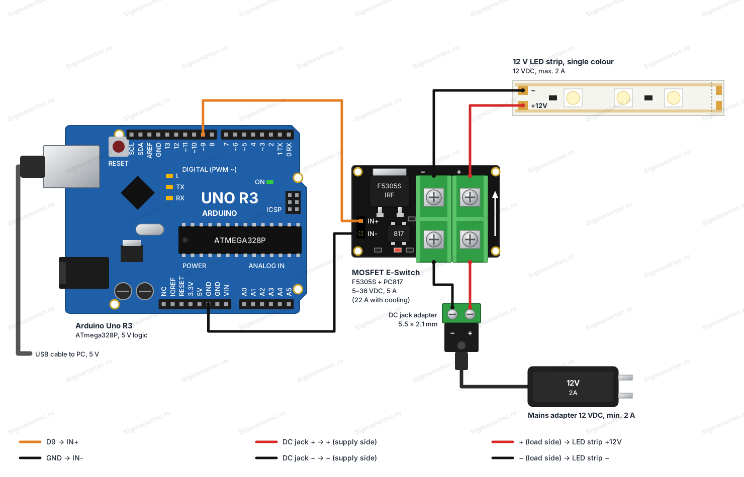
The setup uses a 12 VDC mains power supply with at least 2 A, a 5.5 x 2.1 mm jack adapter with screw terminals and a single-colour 12 V LED strip. Connect everything with the power supply disconnected and power it on last. The two terminal blocks are marked + and -. On the + block, the positive of the supply goes to the screw at the tail of the arrow on the board, and the positive of the load leaves from the screw at the tip of the arrow. The - block is the common negative of the supply and the load. No level converter, pull-up resistors or separate power for the control side are required.
| Product pin | Connects to | Role |
|---|---|---|
| IN+ | Arduino Uno D9 | PWM control signal |
| IN- | Arduino Uno GND | Control signal ground |
| + (first screw, from the tail of the arrow) | Jack adapter, + terminal | 12 VDC supply positive input |
| - (first screw) | Jack adapter, - terminal | Supply negative |
| + (second screw, from the tip of the arrow) | LED strip, +12V wire | Switched output to the load |
| - (second screw) | LED strip, - wire | Load negative |
Board and libraries:
In the Arduino IDE, select at Tools > Board the Arduino Uno board from the Arduino AVR Boards package, which comes installed with the Arduino IDE. The program uses only the basic Arduino functions, so no library needs to be installed.
The code:
The program sets five brightness levels in turn, then performs a smooth increase and decrease of the brightness, printing to the serial monitor what is happening.
/*
  E-Switch MOSFET module with optoisolator (F5305S + PC817) - PWM brightness demo
  Board: Arduino Uno (Tools > Board > Arduino AVR Boards > Arduino Uno)
  Libraries: none, only the core Arduino functions are used.
  Wiring:
    Module IN+  -> Arduino Uno D9 (PWM, about 490 Hz)
    Module IN-  -> Arduino Uno GND
    Module + (screw 1) -> 12 VDC supply +
    Module - (screw 1) -> 12 VDC supply -
    Module + (screw 2) -> 12 V LED strip +12V
    Module - (screw 2) -> 12 V LED strip -
*/
const int MOSFET_PIN = 9;                          // PWM pin connected to IN+
const int LEVELS[] = {0, 64, 128, 192, 255};       // test brightness levels
const int NUM_LEVELS = sizeof(LEVELS) / sizeof(LEVELS[0]);
// Send a PWM value (0 - 255) to the module and print it
void setBrightness(int value) {
  analogWrite(MOSFET_PIN, value);                  // set the duty cycle
  Serial.print("Brightness level: ");
  Serial.print(value);
  Serial.print(" / 255 (");
  Serial.print(value * 100L / 255);                // convert to percent
  Serial.println(" %)");
}
void setup() {
  Serial.begin(9600);                              // start the serial monitor
  pinMode(MOSFET_PIN, OUTPUT);                     // control pin as output
  analogWrite(MOSFET_PIN, 0);                      // start with the load off
  Serial.println("E-Switch MOSFET module test (Arduino Uno, pin D9)");
}
void loop() {
  // Step through the fixed levels, two seconds each
  for (int i = 0; i < NUM_LEVELS; i++) {
    setBrightness(LEVELS[i]);
    delay(2000);
  }
  // Smooth fade up from 0 to 255
  Serial.println("Fade up...");
  for (int value = 0; value <= 255; value++) {
    analogWrite(MOSFET_PIN, value);
    delay(10);
  }
  // Smooth fade down from 255 to 0
  Serial.println("Fade down...");
  for (int value = 255; value >= 0; value--) {
    analogWrite(MOSFET_PIN, value);
    delay(10);
  }
  analogWrite(MOSFET_PIN, 0);                      // load off before repeating
  delay(1000);
}
How the code works:
The constant MOSFET_PIN has the value 9 and indicates the PWM pin to which IN+ is connected. The LEVELS array contains the five test values, 0, 64, 128, 192 and 255, and NUM_LEVELS is their count.
In the setup function, the serial communication is started at 9600 baud, the MOSFET_PIN pin is configured as an output and the value 0 is applied, so that the load starts switched off.
The setBrightness function receives a value between 0 and 255, sends it with analogWrite to the module and prints the value and the corresponding percentage.
In the loop function, a for loop goes through the LEVELS array and keeps each level for two seconds. Then two for loops increase the value from 0 to 255 and decrease it back to 0, with a 10 ms pause between steps, which gives a smooth fade-in and fade-out effect. After a pause of one second the sequence starts again.
Result:
Open the serial monitor at 9600 baud. The LED strip cycles through the five brightness levels, then fades smoothly on and off, and a text similar to the one below appears on the monitor.
E-Switch MOSFET module test (Arduino Uno, pin D9)
Brightness level: 0 / 255 (0 %)
Brightness level: 64 / 255 (25 %)
Brightness level: 128 / 255 (50 %)
Brightness level: 192 / 255 (75 %)
Brightness level: 255 / 255 (100 %)
Fade up...
Fade down...
Brightness level: 0 / 255 (0 %)
Brightness level: 64 / 255 (25 %)
Brightness level: 128 / 255 (50 %)
Common problems:
The load stays on all the time. The most frequent cause is connecting the supply and the load in the opposite direction to the arrow on the board, in which case the current bypasses the MOSFET. Reconnect the supply to the screw at the tail of the arrow and the load to the screw at its tip.
The load does not switch on at all. Check that IN+ is connected to D9 and IN- to GND, that the 12 V supply is powered and that the negative of the supply and of the load are on the - block. Also check that the control voltage is at least 3 V.
The brightness does not vary, the strip only lights fully. Check that the signal is on a PWM pin, marked with ~ on the Uno board, and that the code uses analogWrite, not digitalWrite.
The module heats up strongly. The load current exceeds 5 A without cooling. Reduce the load or fit a heatsink and a fan.
With motors or pumps, the Arduino board resets or behaves unstably. A motor produces voltage spikes when it switches off. Fit a protection diode in parallel with the load, with the cathode towards the positive, and use wires of an adequate gauge.
Limitations and tips:
The module switches only DC loads of 5 - 36 VDC and is not suitable for alternating voltage. The recommended control voltage is 3 - 20 VDC, and the control current is approximately 5 mA. Up to 5 A no cooling is needed, and with a heatsink and a fan it can reach 22 A, while checking the temperature of the MOSFET.
The optocoupler limits the usable PWM frequency, so the approximately 490 Hz from D9 is suitable, but very fast PWM is not recommended. With the same setup you can build a dimmer for the LED strip with a potentiometer, a speed controller for a DC motor or a switch for pumps and solenoid valves controlled by sensors.