
Product images are for informational purposes only and may vary slightly depending on the batch and supplier. Product specifications and prices may be subject to change without notice. We do our best to provide accurate and complete product specifications, but they may not be completely accurate. If you encounter any such situation, please let us know.
The product is intended for specialists and requires qualified and authorized personnel. The product does not include assembly/use instructions . Putting the product into operation by unqualified persons leads to the loss of the warranty according to the Terms and Conditions on the site.
The specified technical parameters (current, power, etc.) represent maximum allowable values under ideal operating conditions. For safe use and optimal lifespan, it is recommended to operate the product continuously at no more than 50% of the specified maximum values.
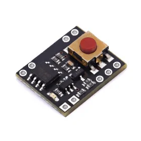
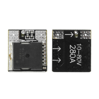
High-power MOSFET switch module, 100V 300A, 5–18V control
Switch high-power DC loads quickly and directly from a logic or PWM signal, without mechanical relays, supporting up to 100V and 300A peaks. Based on the AOTL66912 MOSFET with very low on-resistance for reduced losses, it is driven at 5–18V, ideally 10–12V at high currents, low-side, on an ultra-compact 14x15mm board.
Shipping by Thursday 22 October
Buying this product earns you 0.54 RON in loyalty points.

International fast shipping within EU. Free Shipping for orders above 100 EUR in most EU countries.

We ship from our stock within 24H

You earn points with every order, worth 5%.
The MOSFET power transistor switch module is a compact solution for controlling high-current DC loads. It is intended for electronics enthusiasts and engineers who want to turn motors, LED strips, and other power consumers on, off, or adjust them directly from a microcontroller, without mechanical relays and without moving parts.
The module is built around the AOTL66912 transistor manufactured by Alpha & Omega, an N-channel MOSFET in a TOLL package with very low on-resistance. It supports a continuous current of up to 200A, depending on cooling, an instantaneous peak current of 300A, and a maximum power-path voltage of 100 VDC. Everything is integrated on a board measuring only 14 x 15mm. The board already includes a series gate resistor and a pull-down resistor, which keeps the transistor off when the trigger point is left floating.
Control is done through a single trigger point, marked “+” on the board and connected to the transistor gate. When a positive voltage between 5 and 18 VDC is applied to this point, the transistor turns on and powers the load. When the voltage is removed, the load turns off. There is no separate connector marked PWM. Dimming LED strips or controlling motor speed is achieved by applying a PWM signal to the same trigger point. For high currents, a control voltage of 10 - 12 VDC is recommended, at which the transistor opens fully and heats up the least.
The module switches the negative side of the load (low side). The positive terminal of the supply is connected directly to the positive terminal of the load, while the MOSFET transistor is inserted in the negative path. This configuration simplifies wiring and allows control of loads powered at voltages much higher than that of the microcontroller.
The module can be driven directly by 5V Arduino boards, such as Arduino Uno, Nano, or Mega, for low and moderate current loads. For high currents, a drive stage capable of supplying 10 - 12V to the trigger point is recommended, for example a MOSFET driver or an optocoupler powered at 12V. Boards that operate at 3.3V, such as ESP32, STM32, Raspberry Pi Pico, or Raspberry Pi, do not reach the minimum 5V threshold and always require such a level-shifting stage. The module can also be controlled without a microcontroller, using a simple switch connected to the positive supply.
Specifications:
Type: Electronic switch with power MOSFET transistor
Transistor: AOTL66912, N-channel, TOLL package
On-resistance: below 1.7mΩ at 10V gate drive
Trigger voltage: 5 - 18 VDC
Recommended trigger voltage for high current: 10 - 12 VDC
Continuous current: 10 - 200A (depending on cooling)
Instantaneous peak current: 300A
Maximum power-path voltage: 100 VDC
Switching mode: Negative side of the load (low side)
Control: On/off logic signal or PWM signal
Applications: Motors, LED strips, high-power DC loads
Dimensions: 14 x 15mm
Usage:
Connect the positive terminal of the power supply directly to the positive terminal of the load.
Connect the negative terminal of the load to the module OUT output pad.
Connect the negative terminal of the power supply to the GND pad, located near the transistor pins, so that the MOSFET remains inserted in the load’s negative path.
Apply control to the trigger pad marked “+”, either through a switch connected to the positive supply or through a microcontroller pin.
Direct switch control from the load supply, as shown in the diagram, is possible only if the supply is between 5 and 18V. For loads powered at higher voltages, use a separate 5 - 18V supply for control, with a common ground shared with the module.
If you use a microcontroller, connect its ground (GND) to the module ground. Without a common ground, the control signal has no reference and the module will not work properly.
For simple on/off operation, a HIGH or LOW logic signal is sufficient.
For brightness or speed control, apply a PWM signal to the trigger pad instead of the switch. Use frequencies in the range of hundreds of Hz up to a few kHz, since the transistor has a large gate capacitance.
For high currents, apply 10 - 12V to the trigger pad through a MOSFET driver or an optocoupler. At 5V the transistor does not open fully and heats up more.
For 3.3V boards (ESP32, STM32), always use a level-shifting stage that provides at least 5V, ideally 10 - 12V, to the trigger pad.
When driving motors and other inductive loads, install a flyback protection diode in parallel with the load, with the cathode toward the positive terminal, to protect the transistor from voltage spikes.
Solder the power wires directly to the large pads and use a conductor cross-section suitable for the load current.
For high currents and continuous operation, ensure proper cooling of the transistor, with a heatsink and possibly ventilation, to keep the temperature within safe limits.
Do not exceed the maximum voltage of 100 VDC on the power path or 18 VDC on the trigger pad.

Pinout:
| Point | Function |
|---|---|
| Small round pad marked “+” | Trigger, 5–18 VDC or PWM control |
| Large pad near the transistor pins | Ground (GND), connected to the supply negative |
| Large pad on the opposite side | Output (OUT), connected to the load negative |
Dimensions diagram:

- Maximum Input Voltage
- 100 V
- Maximum Output Current
- 300 A
- Control voltage
- 5 - 18 V
Produs destinat utilizarii in proiecte electronice, automatizari, prototipare, educatie si cercetare.
Produsul trebuie utilizat numai conform specificatiilor tehnice mentionate in descriere si/sau in documentatia produsului.
Avertismente generale de siguranta:
Nu utilizati produsul la tensiuni, curenti sau temperaturi peste valorile specificate.
Montajul si conectarea trebuie realizate de persoane cu cunostinte tehnice minime in domeniul electric/electronic.
Evitati scurtcircuitele, inversarea polaritatii si conectarea gresita a alimentarii.
Nu lasati produsul alimentat nesupravegheat in timpul testelor.
Produsul nu este jucarie si nu este destinat copiilor.
Pentru modulele electronice, se recomanda utilizarea in carcase, panouri sau montaje protejate, dupa caz.
Identificare produs:
Denumirea produsului, codul/SKU-ul si caracteristicile tehnice sunt mentionate in pagina produsului si/sau pe eticheta ambalajului.
Producator / Importator / Distribuitor:
Sigmanortec S.R.L.
Calea Bucuresti nr. 9, Targu Jiu, Gorj, Romania
E-mail: [email protected]
Website: www.sigmanortec.ro
Persoana responsabila in UE:
Sigmanortec S.R.L.
Calea Bucuresti nr. 9, Targu Jiu, Gorj, Romania
E-mail: [email protected]
Documentatie si siguranta:
Pentru informatii suplimentare, fise tehnice, declaratii de conformitate sau instructiuni, ne puteti contacta la [email protected].
// MOSFET power switch module - ON/OFF and PWM test
// Connect the "+" trigger pad to Arduino pin 9
// Connect module GND to Arduino GND (common ground is required)
// Direct 5V drive is intended for testing and low/moderate current loads only
const int triggerPin = 9; // PWM capable pin on Uno/Nano (about 490 Hz)
void setup() {
pinMode(triggerPin, OUTPUT);
digitalWrite(triggerPin, LOW); // Load off at startup
}
void loop() {
// Full ON for 2 seconds
digitalWrite(triggerPin, HIGH);
delay(2000);
// OFF for 2 seconds
digitalWrite(triggerPin, LOW);
delay(2000);
// Ramp up brightness / speed
for (int duty = 0; duty <= 255; duty++) {
analogWrite(triggerPin, duty);
delay(10);
}
// Ramp down brightness / speed
for (int duty = 255; duty >= 0; duty--) {
analogWrite(triggerPin, duty);
delay(10);
}
delay(1000);
}