
Product images are for informational purposes only and may vary slightly depending on the batch and supplier. Product specifications and prices may be subject to change without notice. We do our best to provide accurate and complete product specifications, but they may not be completely accurate. If you encounter any such situation, please let us know.
The product is intended for specialists and requires qualified and authorized personnel. The product does not include assembly/use instructions . Putting the product into operation by unqualified persons leads to the loss of the warranty according to the Terms and Conditions on the site.
The specified technical parameters (current, power, etc.) represent maximum allowable values under ideal operating conditions. For safe use and optimal lifespan, it is recommended to operate the product continuously at no more than 50% of the specified maximum values.
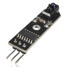
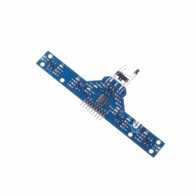
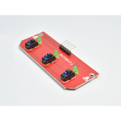
Line Tracking Module, 3 Channels, TCRT5000, 5V
TCRT5000 3-sensor IR module for detecting black lines on light backgrounds, ideal for line-following robots and Arduino projects. Provides 3 separate digital outputs L, C, R for left, center, right positioning and fast direction corrections. Operates at 5V, has integrated comparators for stable signal and status LEDs for quick verification.
Shipping by Thursday 22 October
Buying this product earns you 0.53 RON in loyalty points.

International fast shipping within EU. Free Shipping for orders above 100 EUR in most EU countries.

We ship from our stock within 24H

You earn points with every order, worth 5%.
The module with 3 TCRT5000 sensors, designed for detecting a black line on a light background, compatible with Arduino, and frequently used in line-following robots.
Each sensor operates on the principle of infrared reflection, so that light surfaces reflect differently than dark ones, allowing the robot to determine the position of the line in real time.
The module provides 3 separate outputs, labeled L, C, and R, for left, center, and right, which allows quick direction corrections and easy integration with Arduino or other microcontrollers. The outputs are digital (the sensors are analog but the module integrates a comparator to convert the output into a digital signal 0 and 1).
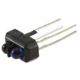
The TCRT5000 sensor has an optical detection distance of approximately 1 mm, which varies depending on adjustment, surface, and ambient light. For this reason, the sensors must be placed very close to the detection surface to reduce the effects of ambient light.
The module integrates status LEDs that visually confirm line detection, useful for troubleshooting and quick functionality checks.
Specifications:
Power supply voltage: 5V
Type: line tracking sensor module
Number of sensors: 3
Sensor model: TCRT5000
Detection type: reflective infrared
Detection: black line
Output: 3 channels
Output: Digital
TCRT5000 sensor optical distance: 0.2 mm - 15 mm
TCRT5000 peak distance: approx. 2.5 mm
Practical distance on line tracking modules: approx. 1 mm - 2 mm, depending on adjustment and surface
Pinout:
| Pin | Description |
|---|---|
| VCC | Module power supply, usually 5V |
| GND | Ground |
| L | Left sensor output |
| C | Center sensor output |
| R | Right sensor output |
Usage:
The module is connected to 5V and GND, and the L, C, and R outputs are connected to the microcontroller's digital pins.
In operation, each sensor separately reads the surface beneath it, and the controller decides whether the robot moves forward, turns left, or turns right. For good results, the sensors should be mounted close to the ground, usually 1-2 millimeters from the surface, and the track should have clear contrast. The actual detection distance depends on the material's color and ambient light.
- Input Voltage
- 5 V
- Input Voltage Type
- “DC” in Romanian can mean **“de ce”**, which translates to **“why”** in English.
Produs destinat utilizarii in proiecte electronice, automatizari, prototipare, educatie si cercetare.
Produsul trebuie utilizat numai conform specificatiilor tehnice mentionate in descriere si/sau in documentatia produsului.
Avertismente generale de siguranta:
Nu utilizati produsul la tensiuni, curenti sau temperaturi peste valorile specificate.
Montajul si conectarea trebuie realizate de persoane cu cunostinte tehnice minime in domeniul electric/electronic.
Evitati scurtcircuitele, inversarea polaritatii si conectarea gresita a alimentarii.
Nu lasati produsul alimentat nesupravegheat in timpul testelor.
Produsul nu este jucarie si nu este destinat copiilor.
Pentru modulele electronice, se recomanda utilizarea in carcase, panouri sau montaje protejate, dupa caz.
Identificare produs:
Denumirea produsului, codul/SKU-ul si caracteristicile tehnice sunt mentionate in pagina produsului si/sau pe eticheta ambalajului.
Producator / Importator / Distribuitor:
Sigmanortec S.R.L.
Calea Bucuresti nr. 9, Targu Jiu, Gorj, Romania
E-mail: [email protected]
Website: www.sigmanortec.ro
Persoana responsabila in UE:
Sigmanortec S.R.L.
Calea Bucuresti nr. 9, Targu Jiu, Gorj, Romania
E-mail: [email protected]
Documentatie si siguranta:
Pentru informatii suplimentare, fise tehnice, declaratii de conformitate sau instructiuni, ne puteti contacta la [email protected].
TEST CODE:
const int leftSensor = 2;
const int centerSensor = 3;
const int rightSensor = 4;
void setup() {
pinMode(leftSensor, INPUT);
pinMode(centerSensor, INPUT);
pinMode(rightSensor, INPUT);
Serial.begin(9600);
}
void loop() {
int leftState = digitalRead(leftSensor);
int centerState = digitalRead(centerSensor);
int rightState = digitalRead(rightSensor);
Serial.print("L: ");
Serial.print(leftState);
Serial.print(" C: ");
Serial.print(centerState);
Serial.print(" R: ");
Serial.println(rightState);
if (centerState == LOW && leftState == HIGH && rightState == HIGH) {
Serial.println("Move forward");
} else if (leftState == LOW) {
Serial.println("Turn left");
} else if (rightState == LOW) {
Serial.println("Turn right");
} else {
Serial.println("Line lost or stop");
}
delay(100);
}
LINE FOLLOWER CODE, H BRIDGE:
// 3-channel line follower with H-bridge driver
// Assumption: sensor output is LOW when black line is detected
const int sensorLeft = 2;
const int sensorCenter = 3;
const int sensorRight = 4;
// Motor driver pins
const int ENA = 5;
const int IN1 = 6;
const int IN2 = 7;
const int IN3 = 8;
const int IN4 = 9;
const int ENB = 10;
// Speed values
const int baseSpeed = 150;
const int turnSpeed = 130;
void setup() {
pinMode(sensorLeft, INPUT);
pinMode(sensorCenter, INPUT);
pinMode(sensorRight, INPUT);
pinMode(ENA, OUTPUT);
pinMode(IN1, OUTPUT);
pinMode(IN2, OUTPUT);
pinMode(IN3, OUTPUT);
pinMode(IN4, OUTPUT);
pinMode(ENB, OUTPUT);
stopMotors();
}
void loop() {
int L = digitalRead(sensorLeft);
int C = digitalRead(sensorCenter);
int R = digitalRead(sensorRight);
// LOW = black line detected
if (C == LOW && L == HIGH && R == HIGH) {
moveForward(baseSpeed, baseSpeed);
}
else if (L == LOW && C == HIGH) {
turnLeft(turnSpeed, baseSpeed);
}
else if (R == LOW && C == HIGH) {
turnRight(baseSpeed, turnSpeed);
}
else if (L == LOW && C == LOW && R == HIGH) {
turnLeft(100, baseSpeed);
}
else if (R == LOW && C == LOW && L == HIGH) {
turnRight(baseSpeed, 100);
}
else if (L == LOW && C == LOW && R == LOW) {
moveForward(baseSpeed, baseSpeed);
}
else {
stopMotors();
}
delay(10);
}
void moveForward(int leftSpeed, int rightSpeed) {
digitalWrite(IN1, HIGH);
digitalWrite(IN2, LOW);
digitalWrite(IN3, HIGH);
digitalWrite(IN4, LOW);
analogWrite(ENA, leftSpeed);
analogWrite(ENB, rightSpeed);
}
void turnLeft(int leftSpeed, int rightSpeed) {
digitalWrite(IN1, LOW);
digitalWrite(IN2, LOW);
digitalWrite(IN3, HIGH);
digitalWrite(IN4, LOW);
analogWrite(ENA, leftSpeed);
analogWrite(ENB, rightSpeed);
}
void turnRight(int leftSpeed, int rightSpeed) {
digitalWrite(IN1, HIGH);
digitalWrite(IN2, LOW);
digitalWrite(IN3, LOW);
digitalWrite(IN4, LOW);
analogWrite(ENA, leftSpeed);
analogWrite(ENB, rightSpeed);
}
void stopMotors() {
digitalWrite(IN1, LOW);
digitalWrite(IN2, LOW);
digitalWrite(IN3, LOW);
digitalWrite(IN4, LOW);
analogWrite(ENA, 0);
analogWrite(ENB, 0);
}