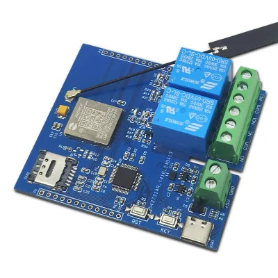


Product images are for informational purposes only and may vary slightly depending on the batch and supplier. Product specifications and prices may be subject to change without notice. We do our best to provide accurate and complete product specifications, but they may not be completely accurate. If you encounter any such situation, please let us know.
The product is intended for specialists and requires qualified and authorized personnel. The product does not include assembly/use instructions . Putting the product into operation by unqualified persons leads to the loss of the warranty according to the Terms and Conditions on the site.
The specified technical parameters (current, power, etc.) represent maximum allowable values under ideal operating conditions. For safe use and optimal lifespan, it is recommended to operate the product continuously at no more than 50% of the specified maximum values.
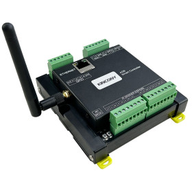
STM32F103 development board, 4G Air780E module, 5V double relay, for IoT
Integrated solution for IoT projects with 4G connectivity and external load control, based on STM32F103 and Air780E LTE Cat.1 bis module with AT firmware and low idle power consumption. Includes two 5V relays controlled from PA4 and PA5, flip-up Nano SIM slot with 4G antenna and network status LED. Simple 5V power supply via USB Type-C or KF128 terminal, easy programming via SWD or USART.
Buying this product earns you 7.84 RON in loyalty points.

International fast shipping within EU. Free Shipping for orders above 100 EUR in most EU countries.

We ship from our stock within 24H

You earn points with every order, worth 5%.
This development board represents a complete and integrated solution for IoT projects requiring 4G connectivity and control of external loads. It combines an STM32F103C6T6 microcontroller with an Air780E LTE Cat.1 bis communication module, offering a versatile solution for both rapid prototyping and industrial implementations.
The Air780E module supports 4G and is designed for energy efficiency, with a standby current consumption of only 600µA. Factory-installed, the module uses AT firmware and communicates with the STM32 via the serial port, using standard AT commands for data transmission and reception over the network. The board includes two 5V relays, which can be controlled through PA4 and PA5, allowing direct control of external devices such as lighting, fans, pumps, or other equipment.
The board integrates a flip-up type Nano SIM card slot (easy to install and remove), a dedicated 4G antenna, a blue LED indicating the Air780E network status, LEDs for relay status, a reset button, and a user-programmable button. Power can be supplied either via the Type-C port or through the KF128 terminal.
Specifications:
Microcontroller: STM32F103C6T6 based on ARM architecture, 32-bit
4G Module: Air780E LTE Cat.1 bis
Network connectivity: full 4G network
Power consumption: 600µA in standby mode
Power supply: 5 VDC via USB or KF128 terminal
Relays: 2 x 5V, controlled via PA4 and PA5
SIM Slot: Flip-up type for Nano SIM
LED Indicators: Blue for Air780E network status, LEDs for relay status
Buttons: Reset and programmable button
Programming interfaces: USART (TTL) and SWD
Accessible pins: STM32 and Air780E pins brought out
Default firmware: AT firmware on Air780E, communicates with STM32 via AT commands
Dimensions: 62 x 72.5 mm
Layout:
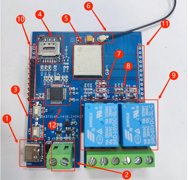
1. USB Type C interface
2. KF128 power terminal
3. Reset button (RST) and user-programmable button KEY (PB12)
4. Nano SIM card holder
5. Air780e module
6. Antenna
7. Blue LED for network status, it blinks intermittently after power-on and blinks faster when connected to the network
8. LED for relay status
9. Double relay, 5V
10. Common IO pins for STM32
11. Common IO pins for Air780e
12. MCU: STM32F103C6T6 (LQFP-48)
Pinout:
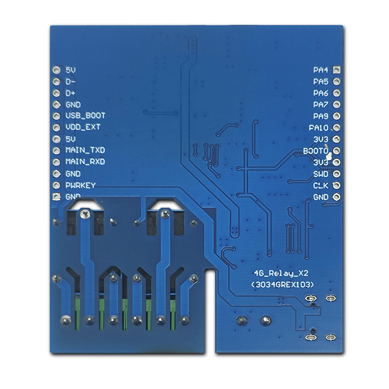
| Connector | Pin | Role | Notes |
|---|---|---|---|
| Left | 5V | 5V Power | 5V input, same line as USB Type-C power supply |
| Left | D- | USB data minus | USB data line |
| Left | D+ | USB data plus | USB data line |
| Left | GND | Ground | Common reference |
| Left | USB_BOOT | USB boot mode | Startup mode selection related to USB, useful for programming service |
| Left | VDD_EXT | External logic power supply | External power line for peripherals, depending on board implementation |
| Left | 5V | 5V Power | Duplicate on header for quick access |
| Left | MAIN_TXD | Main UART TX | Serial line, usually to the 4G module for AT commands |
| Left | MAIN_RXD | Main UART RX | Serial line, paired with MAIN_TXD |
| Left | GND | Ground | Common reference |
| Left | PWRKEY | Module power control | Power on/off 4G module via PWRKEY signal |
| Left | GND | Ground | Common reference |
| Right | PA4 | Relay 1 control | STM32 digital output for relay 1 |
| Right | PA5 | Relay 2 control | STM32 digital output for relay 2 |
| Right | PA6 | General IO STM32 | Available pin for input/output |
| Right | PA7 | General IO STM32 | Available pin for input/output |
| Right | PA9 | USART1 TX | Serial for debugging or external communication |
| Right | PA10 | USART1 RX | Serial for debugging or external communication |
| Right | 3V3 | 3.3V Power | For peripherals at 3.3V |
| Right | BOOT0 | STM32 boot selection | For bootloader, useful for programming via USART |
| Right | 3V3 | 3.3V Power | Duplicate on header for quick access |
| Right | SWD | SWDIO | Data line for SWD programming and debugging |
| Right | CLK | SWCLK | Clock line for SWD programming and debugging |
| Right | GND | Ground | Common reference |
Usage:
Insert an active Nano SIM card into the flip-up slot before powering on. Connect the 4G antenna to the dedicated connector. Power the board either via the USB port or the KF128 terminal.
The factory program on the board makes the STM32 send AT commands to the Air780E to connect to the network. After a successful connection, the blue network status LED will blink at an increased rate, and the two relays will activate automatically. This is the factory program intended to test 4G connectivity.
Custom programming via USART:
To upload your own firmware via USART, use a TTL serial module (e.g., CH340). Connect the module as follows:
| TTL Serial Module | Development Board |
|---|---|
| GND | GND |
| TX | RX |
| RX | TX |
| 3.3V | 3.3V |
Then place a jumper between the BOOT0 pin and 3.3V to allow firmware burning.
Custom programming via SWD:
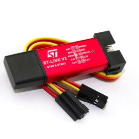
For programming via SWD, use a Link debugger (ST Link, J-Link, etc). Connect the debugger as follows:
| Link Debugger | Development Board |
|---|---|
| GND | GND |
| SWCLK | DCK |
| SWDIO | DIO |
| 3.3V | 3.3V |
Package contents:
1 x STM32 Development Board with Dual Relay and Air780E 4G CAT1 Module
1 x Dedicated 4G Antenna
2 x 12-pin male headers
Produs destinat utilizarii in proiecte electronice, automatizari, prototipare, educatie si cercetare.
Produsul trebuie utilizat numai conform specificatiilor tehnice mentionate in descriere si/sau in documentatia produsului.
Avertismente generale de siguranta:
Nu utilizati produsul la tensiuni, curenti sau temperaturi peste valorile specificate.
Montajul si conectarea trebuie realizate de persoane cu cunostinte tehnice minime in domeniul electric/electronic.
Evitati scurtcircuitele, inversarea polaritatii si conectarea gresita a alimentarii.
Nu lasati produsul alimentat nesupravegheat in timpul testelor.
Produsul nu este jucarie si nu este destinat copiilor.
Pentru modulele electronice, se recomanda utilizarea in carcase, panouri sau montaje protejate, dupa caz.
Identificare produs:
Denumirea produsului, codul/SKU-ul si caracteristicile tehnice sunt mentionate in pagina produsului si/sau pe eticheta ambalajului.
Producator / Importator / Distribuitor:
Sigmanortec S.R.L.
Calea Bucuresti nr. 9, Targu Jiu, Gorj, Romania
E-mail: [email protected]
Website: www.sigmanortec.ro
Persoana responsabila in UE:
Sigmanortec S.R.L.
Calea Bucuresti nr. 9, Targu Jiu, Gorj, Romania
E-mail: [email protected]
Documentatie si siguranta:
Pentru informatii suplimentare, fise tehnice, declaratii de conformitate sau instructiuni, ne puteti contacta la [email protected].