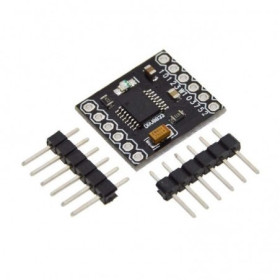

Product images are for informational purposes only and may vary slightly depending on the batch and supplier. Product specifications and prices may be subject to change without notice. We do our best to provide accurate and complete product specifications, but they may not be completely accurate. If you encounter any such situation, please let us know.
The product is intended for specialists and requires qualified and authorized personnel. The product does not include assembly/use instructions . Putting the product into operation by unqualified persons leads to the loss of the warranty according to the Terms and Conditions on the site.
The specified technical parameters (current, power, etc.) represent maximum allowable values under ideal operating conditions. For safe use and optimal lifespan, it is recommended to operate the product continuously at no more than 50% of the specified maximum values.
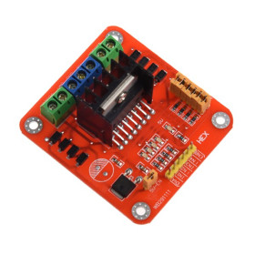
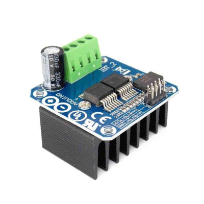
Power H-bridge, motor driver, BTS7960, 43A
H-bridge module for controlling high-torque DC motors, ideal for Arduino and other boards, delivers up to 43A and operates at 5.5-27V. Integrates BTS7960 and 74HC244 for stable PWM control up to 25kHz, offers temperature, overcurrent and short circuit protection, and the generous heat sink ensures strong starting, acceleration and braking in demanding applications.
Shipping by Thursday 22 October
Buying this product earns you 1.78 RON in loyalty points.

International fast shipping within EU. Free Shipping for orders above 100 EUR in most EU countries.

We ship from our stock within 24H

You earn points with every order, worth 5%.
The BTS7960 motor driver module is a high-power full H-bridge, with a maximum current of 43A, intended for controlling high-current DC motors. The H-bridge is made up of two BTS7960 integrated circuits, each being a power half-bridge with built-in thermal and overcurrent protection. The 74HC244 circuit acts as a buffer between the microcontroller and the power stage and protects the microcontroller outputs.
The module’s main features are: a full H-bridge built with two BTS7960 ICs, maximum current of 43A, motor supply voltage between 5.5V and 27V, 5V control logic, PWM control with frequency up to 25 kHz, protection against overtemperature, overvoltage, overcurrent and short circuit, 74HC244 buffer for separating control signals from the H-bridge, outputs for current monitoring (R_IS and L_IS), and a generously sized heatsink.
The generous heatsink and high power of the module ensure strong motor movement and braking. The module is suitable for mobile robots, small electric vehicles, RC cars, linear actuators, winches, or other high-power DC motor applications. The value of 43A represents the current limiting threshold of the BTS7960 ICs. The continuous current capability depends on cooling and operating conditions, therefore for heavy loads and long operation additional ventilation is recommended.
Bridge control is performed via PWM signal, in two possible configurations: with the PWM signal applied to the direction pins (R_PWM and L_PWM) or to the enable pins (R_EN and L_EN).
The module is compatible with Arduino and other development boards that can generate PWM signals, such as STM32, ESP32 or Raspberry Pi Pico. The module logic operates at 5V, so for boards with 3.3V logic a level shifter is recommended.
Important: DO NOT send a HIGH signal simultaneously to both dedicated direction pins (L_PWM and R_PWM).
Specifications:
ICs: 2 x BTS7960, 74HC244
Driver type: Full H-bridge
Maximum current: 43A
Supply voltage: 5.5 - 27V
Logic voltage: 5V
Control signal: PWM or 5V
PWM frequency: Up to 25 kHz
Temperature protection: Yes
Overvoltage protection: Yes
Current protection: Yes
Short-circuit protection: Yes
Dimensions: 40 x 50 x 12 mm
Pins:

| No. | Pin | Function |
|---|---|---|
| 1 | R_PWM | PWM signal or 5V, clockwise rotation |
| 2 | L_PWM | PWM signal or 5V, counterclockwise rotation |
| 3 | R_EN | Right half-bridge enable (HIGH = active) |
| 4 | L_EN | Left half-bridge enable (HIGH = active) |
| 5 | R_IS | Current monitoring output, right half-bridge |
| 6 | L_IS | Current monitoring output, left half-bridge |
| 7 | VCC | 5V logic supply |
| 8 | GND | Logic ground |
| – | B+ | Motor supply, positive terminal (5.5–27V) |
| – | B- | Motor supply, negative terminal |
| – | M+ | Motor output |
| – | M- | Motor output |
Instructions:
The H-bridge can be used in two different configurations:
Setup 1:
VCC - 5V from the Microcontroller
GND - GND from the Microcontroller
L_PWM - PWM signal or 5V, counterclockwise rotation
R_PWM - PWM signal or 5V, clockwise rotation
R_EN and L_EN - 5V from the Microcontroller
Setup 2:
VCC - 5V from the Microcontroller
GND - GND from the Microcontroller
L_PWM - 5V from the Microcontroller, counterclockwise rotation
R_PWM - 5V from the Microcontroller, clockwise rotation
R_EN and L_EN - PWM signal from the Microcontroller
Usage:
Connect the motor to the M+ and M- terminals of the module.
Connect the motor power supply (5.5 - 27V) to the B+ and B- terminals, observing polarity. Use wires with a cross-section appropriate for the current drawn by the motor.
Connect the module’s VCC and GND pins to 5V and GND from the microcontroller.
Connect the control pins according to one of the two configurations, Setup 1 or Setup 2.
In Setup 1, set the rotation direction by applying a PWM signal to R_PWM (clockwise) or to L_PWM (counterclockwise), with the other pin kept LOW. Motor speed is determined by the PWM duty cycle.
In Setup 2, set the rotation direction by setting R_PWM HIGH (clockwise) or L_PWM HIGH (counterclockwise), with the other pin kept LOW. Speed is adjusted by the PWM signal applied to R_EN and L_EN.
For braking, set both R_PWM and L_PWM LOW, with R_EN and L_EN active. For free stop, without braking, set R_EN and L_EN LOW.
Never send a HIGH signal simultaneously to both R_PWM and L_PWM. When changing direction, first set the current direction pin LOW, then activate the opposite direction pin.
For high-power motors, reduce speed or stop the motor before changing direction to avoid current spikes.
The actual rotation direction depends on how the motor is connected. If the motor rotates the wrong way, swap the wires at M+ and M-.
For boards with 3.3V logic (ESP32, STM32), use a logic level converter between the microcontroller pins and the module control pins.
Optionally, the R_IS and L_IS outputs can be read with an analog pin for current monitoring. If not used, they may remain unconnected.
During high-current operation, periodically check the heatsink temperature.
Warning:
The heatsink can become very hot during high-current operation. Do not touch it during operation or immediately after shutdown.
Observe polarity at the B+ and B- terminals. Reversing polarity may destroy the module.
Use a fuse on the motor supply, sized according to the motor’s consumption.
Do not exceed the maximum voltage of 27V. During braking, the motor may generate voltage spikes on the supply line.
Do not connect or disconnect the motor while the module is powered.
The module does not provide galvanic isolation. The microcontroller ground is common with the power ground.
Arduino Pinout Test:
| Module Pin | Arduino UNO Pin | Function |
|---|---|---|
| R_PWM | D5 (PWM) | Clockwise rotation |
| L_PWM | D6 (PWM) | Counterclockwise rotation |
| R_EN | D7 | Right half-bridge enable |
| L_EN | D8 | Left half-bridge enable |
| R_IS | Unconnected (optional A0) | Right current monitoring |
| L_IS | Unconnected (optional A1) | Left current monitoring |
| VCC | 5V | Logic supply |
| GND | GND | Common ground |
| B+ | External supply + | Motor supply (5.5–27V) |
| B- | External supply - | Motor supply ground |
| M+ | Motor | Motor terminal |
| M- | Motor | Motor terminal |
- Maximum Output Current
- 43 A
- Input Voltage Type
- “DC” in Romanian can mean **“de ce”**, which translates to **“why”** in English.
Produs destinat utilizarii in proiecte electronice, automatizari, prototipare, educatie si cercetare.
Produsul trebuie utilizat numai conform specificatiilor tehnice mentionate in descriere si/sau in documentatia produsului.
Avertismente generale de siguranta:
Nu utilizati produsul la tensiuni, curenti sau temperaturi peste valorile specificate.
Montajul si conectarea trebuie realizate de persoane cu cunostinte tehnice minime in domeniul electric/electronic.
Evitati scurtcircuitele, inversarea polaritatii si conectarea gresita a alimentarii.
Nu lasati produsul alimentat nesupravegheat in timpul testelor.
Produsul nu este jucarie si nu este destinat copiilor.
Pentru modulele electronice, se recomanda utilizarea in carcase, panouri sau montaje protejate, dupa caz.
Identificare produs:
Denumirea produsului, codul/SKU-ul si caracteristicile tehnice sunt mentionate in pagina produsului si/sau pe eticheta ambalajului.
Producator / Importator / Distribuitor:
Sigmanortec S.R.L.
Calea Bucuresti nr. 9, Targu Jiu, Gorj, Romania
E-mail: [email protected]
Website: www.sigmanortec.ro
Persoana responsabila in UE:
Sigmanortec S.R.L.
Calea Bucuresti nr. 9, Targu Jiu, Gorj, Romania
E-mail: [email protected]
Documentatie si siguranta:
Pentru informatii suplimentare, fise tehnice, declaratii de conformitate sau instructiuni, ne puteti contacta la [email protected].
Reviews (4) - Review moderation

De incredere
Funcsioneaza conform descrierii, transportul si ambalajul perfect. Recomand.
Livrare rapida
eu l-am folosit pt inchidere-deschidere solar... functioneaza perfect!!!
// BTS7960 H-bridge motor driver test - Setup 1
// Wiring: R_PWM -> D5, L_PWM -> D6, R_EN -> D7, L_EN -> D8, VCC -> 5V, GND -> GND
// Default Arduino UNO PWM on D5/D6 is about 980 Hz, a slight motor whine is normal
const int R_PWM = 5; // PWM pin, clockwise rotation
const int L_PWM = 6; // PWM pin, counterclockwise rotation
const int R_EN = 7; // Right half-bridge enable
const int L_EN = 8; // Left half-bridge enable
// Never drive R_PWM and L_PWM HIGH at the same time
void clockwise(int speed) {
analogWrite(L_PWM, 0); // Turn off the opposite direction first
analogWrite(R_PWM, speed); // speed: 0 - 255
}
void counterClockwise(int speed) {
analogWrite(R_PWM, 0); // Turn off the opposite direction first
analogWrite(L_PWM, speed);
}
void brake() {
analogWrite(R_PWM, 0); // Both outputs to GND with enable HIGH = active braking
analogWrite(L_PWM, 0);
}
void setup() {
pinMode(R_PWM, OUTPUT);
pinMode(L_PWM, OUTPUT);
pinMode(R_EN, OUTPUT);
pinMode(L_EN, OUTPUT);
brake(); // Start with both direction pins LOW
digitalWrite(R_EN, HIGH); // Enable both half-bridges
digitalWrite(L_EN, HIGH);
}
void loop() {
// Clockwise: soft start, run, soft stop
for (int s = 0; s <= 255; s += 5) { clockwise(s); delay(20); }
delay(2000);
for (int s = 255; s >= 0; s -= 5) { clockwise(s); delay(20); }
brake();
delay(1000);
// Counterclockwise: soft start, run, soft stop
for (int s = 0; s <= 255; s += 5) { counterClockwise(s); delay(20); }
delay(2000);
for (int s = 255; s >= 0; s -= 5) { counterClockwise(s); delay(20); }
brake();
delay(1000);
}