
Product images are for informational purposes only and may vary slightly depending on the batch and supplier. Product specifications and prices may be subject to change without notice. We do our best to provide accurate and complete product specifications, but they may not be completely accurate. If you encounter any such situation, please let us know.
The product is intended for specialists and requires qualified and authorized personnel. The product does not include assembly/use instructions . Putting the product into operation by unqualified persons leads to the loss of the warranty according to the Terms and Conditions on the site.
The specified technical parameters (current, power, etc.) represent maximum allowable values under ideal operating conditions. For safe use and optimal lifespan, it is recommended to operate the product continuously at no more than 50% of the specified maximum values.
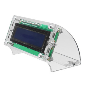
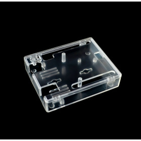
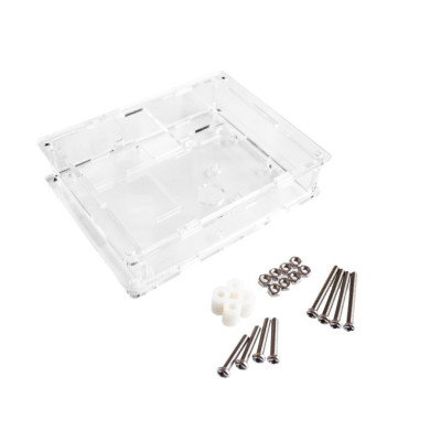
Transparent acrylic case LCR-T4, for M328 tester, assembly kit with screws
Protects the LCR-T4 M328 tester during use and transport. The transparent acrylic case gives quick access to the display and buttons, keeps the board stable and reduces the risk of accidental contact. It is lightweight and sturdy, assembles quickly and gives the equipment a neat appearance.
Shipping by Wednesday 11 November
Buying this product earns you Ft48.95 in loyalty points.

International fast shipping within EU. Free Shipping for orders above 100 EUR in most EU countries.

We ship from our stock within 24H

You earn points with every order, worth 5%.
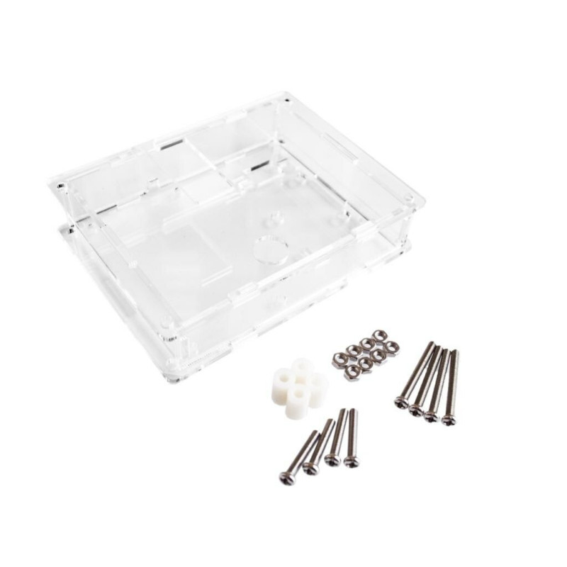
The transparent acrylic case for the LCR-T4 M328 component tester protects the tester board from transistors, diodes, resistors and capacitors. The board no longer remains exposed on the workbench, and the display and button stay visible through the transparent acrylic. It is supplied as an assembly kit, which you assemble yourself.
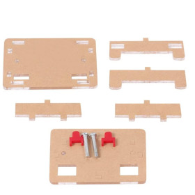
The case body is made of transparent acrylic panels, fixed together and to the board with metal screws and nuts. The panels have cutouts for the parts of the tester that must remain accessible, for example the button and the component test socket. Plastic spacers keep the board at a distance from the panels, so that the solder joints and the display are not pressed by the acrylic.
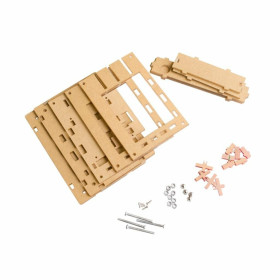
The main features include the transparent acrylic panels, metal screws in two lengths for stacks of different thicknesses, locking nuts and plastic spacers for fixing the board. The case has no electrical connections and requires no power supply, and the tester continues to work from its 9 V battery.

Specifications:
Material: Transparent acrylic
Compatibility: LCR-T4 M328 tester
Kit contents: Acrylic panels, metal screws in two lengths, nuts, plastic spacers
Product type: Assembly kit, unassembled
Usage:
Prepare a clean, flat surface and place all the parts of the kit on it.
Disconnect the 9 V battery from the tester and remove the components from the test socket, to avoid an accidental short circuit while working with metal screws near the board.
If the panels have protective film, remove it from both faces of each panel before assembly, otherwise the case will remain cloudy.
Place the panels next to the board and match the cutouts with the button and the test socket. If a panel does not fit, turn it over to the other side before forcing anything.
Insert the screws through the holes in the panels and the board, and place the plastic spacers between the board and the panel, at each fixing hole. Use the long screws for thick stacks of parts and the short ones for thin stacks.
Place the nuts on the ends of the screws and tighten them by hand first. Then tighten the screws gradually, a little at a time, in a crosswise pattern, so that the panels settle evenly.
Do not overtighten beyond the point where the assembly becomes rigid, because acrylic is brittle and can crack.
Reconnect the 9 V battery and check that nothing presses on the panels or the solder joints.
Press the button through the cutout and check that the display turns on, then insert a component into the test socket and check that it sits easily through the cutout. If anything touches the wall of the case, loosen the screws in a crosswise pattern, adjust the position of the part and tighten again.
For a clean appearance, wipe the case with a soft, dry cloth, without solvents.
- Material
- Transparent acrylic
- Type
- Assembly kit, unassembled
- Compatibility
- LCR-T4 M328 tester
Produs destinat utilizarii in proiecte electronice, automatizari, prototipare, educatie si cercetare.
Produsul trebuie utilizat numai conform specificatiilor tehnice mentionate in descriere si/sau in documentatia produsului.
Avertismente generale de siguranta:
Nu utilizati produsul la tensiuni, curenti sau temperaturi peste valorile specificate.
Montajul si conectarea trebuie realizate de persoane cu cunostinte tehnice minime in domeniul electric/electronic.
Evitati scurtcircuitele, inversarea polaritatii si conectarea gresita a alimentarii.
Nu lasati produsul alimentat nesupravegheat in timpul testelor.
Produsul nu este jucarie si nu este destinat copiilor.
Pentru modulele electronice, se recomanda utilizarea in carcase, panouri sau montaje protejate, dupa caz.
Identificare produs:
Denumirea produsului, codul/SKU-ul si caracteristicile tehnice sunt mentionate in pagina produsului si/sau pe eticheta ambalajului.
Producator / Importator / Distribuitor:
Sigmanortec S.R.L.
Calea Bucuresti nr. 9, Targu Jiu, Gorj, Romania
E-mail: [email protected]
Website: www.sigmanortec.ro
Persoana responsabila in UE:
Sigmanortec S.R.L.
Calea Bucuresti nr. 9, Targu Jiu, Gorj, Romania
E-mail: [email protected]
Documentatie si siguranta:
Pentru informatii suplimentare, fise tehnice, declaratii de conformitate sau instructiuni, ne puteti contacta la [email protected].
Reviews (16) - Review moderation

legat cumva de aparatul pe care-l deserveste.
Am ovalizat cele 4 orificii de fixare a placii LCR in directia bateriei cu cca 1 mm. A rezultat o asamblare usoara, butonul/levierul se misca lejer si cablajul afisajului nu mai atinge peretele superior. Suruburile mari putin prea lungi si ar fi mai estetice 4 piulite infundate. Am primit la termen comanda si recomand furnizorul.
Bun!
O.K.
Nu am avut probleme la montare sa potrivit la fix la aparat.
The transparent acrylic case for the LCR-T4 M328 tester is a mechanical accessory that protects the tester board for transistors, diodes, resistors and capacitors. The tutorial is a step-by-step assembly guide with no electrical connections and no program.
After assembly, the tester can sit on the workbench or in the toolbox without being exposed to scratches and accidental touches, and the display remains visible through the acrylic.
How it works:
The case is made of transparent acrylic panels with cutouts for the parts of the board that must stay accessible, for example the button and the component test socket. The panels are joined to each other and to the board with screws, nuts and plastic spacers.
The spacers keep the board at a distance from the panels, so that the solder joints and the display are not pressed by the acrylic.
Screw length matters. The screw must pass through the stacked panels, the board and the spacer, so where the stack is thick use the long screws, and where only the panels or a thin stack are clamped use the short screws. This is why the set contains screws in two lengths.
Connection:
The case has no electrical connections and does not need power. The link with the tester is strictly mechanical, and the table shows the role of each part in the set. Before assembly, disconnect the 9 V battery from the tester.
| Product part | Connects to | Role |
|---|---|---|
| Acrylic panels | Between each other and around the LCR-T4 board | Form the body of the case and protect the board |
| Metal screws (two lengths) | The holes of the panels, of the spacers and of the board | Secure the panels and the board in a rigid assembly |
| Nuts | The ends of the screws | Lock the screws and tighten the assembly |
| Plastic spacers | Between the board and the panels | Keep the distance between the board and the acrylic |
Step-by-step assembly:
Prepare a clean, flat surface and lay out all the parts of the set on it. If the panels have protective film, remove it from both faces of each panel before assembly, otherwise you will have to take the case apart later.
Disconnect the 9 V battery from the tester and remove the components from the test socket. The board must be without power for the entire assembly process.
Place the panels next to the board and match the cutouts with the elements of the board. The cutout for the button must be aligned with the button, and the one for the test socket with the socket. If a panel does not fit, turn it over to the other face before forcing anything.
Insert the screws through the holes of the panels and of the board. Place the plastic spacers between the board and the panel, at each fixing hole. Choose the screw according to the thickness of the stack, the long ones for thick stacks and the short ones for thin stacks.
Put the nuts on the ends of the screws and tighten them by hand, without locking them yet. When all the parts are in place, tighten the screws gradually, a little at a time, in a cross pattern. This way the panels settle evenly and do not crack. Do not overtighten past the point where the assembly becomes rigid.
Connect the 9 V battery to the tester connector and check that it does not press on the panels or on the solder joints. If the battery fits with difficulty, move it into the free space inside the case, without forcing the panels.
Press the button through the cutout in the case and check that the display turns on. Insert a component into the test socket and check that it can be placed easily through the cutout. If anything touches the wall of the case, loosen the screws in a cross pattern, adjust the position of the part and tighten again.
Usage example:
Use the LCR-T4 tester to sort transistors and capacitors removed from old equipment. Mount the case following the steps above and keep the tester on the workbench, in the place where you usually leave it without protection.
Press the button through the cutout in the case to turn on the tester. Insert the component into the test socket, read the result on the display through the transparent acrylic, then press the button again for the next measurement. At the end, disconnect the battery so that it does not discharge while the tester is not in use.
Common problems:
The panels do not fit together or the cutouts do not line up with the button. The usual cause is a panel placed on the wrong face or turned the wrong way. Take the parts apart, fit the panel in the correct position and assemble again.
An acrylic panel has cracked. The cause is usually tightening one screw too strongly or tightening one screw fully before the others. Tighten the screws gradually, in a cross pattern, and stop when the assembly is rigid. Cracked parts must be replaced, because the crack spreads.
The case remains cloudy or has a matt appearance. The cause is the protective film left on one of the faces of the panels. Take the case apart, remove the film from both faces of each panel and assemble again.
The display or the button is hard to use after assembly. The cause is a part touching the wall of the case or a screw that is too long and presses on the board. Take the assembly apart, check the length of the screws and adjust the position of the board.
The tester no longer turns on after assembly. The possible cause is a weak battery contact or a screw touching the solder joints on the board. Disconnect the battery, check that no metal is in contact with the circuitry and reconnect.
Limitations and tips:
The case is an assembly kit for bench use, without sealing, so it does not protect against moisture or fine dust. The acrylic is fragile under strong tightening and impacts, and the surface scratches if wiped with abrasive materials.
Avoid solvents and concentrated alcohol when cleaning, because they can make the acrylic matt or cause cracks. Use a soft, dry cloth or a little mild detergent.