

Product images are for informational purposes only and may vary slightly depending on the batch and supplier. Product specifications and prices may be subject to change without notice. We do our best to provide accurate and complete product specifications, but they may not be completely accurate. If you encounter any such situation, please let us know.
The product is intended for specialists and requires qualified and authorized personnel. The product does not include assembly/use instructions . Putting the product into operation by unqualified persons leads to the loss of the warranty according to the Terms and Conditions on the site.
The specified technical parameters (current, power, etc.) represent maximum allowable values under ideal operating conditions. For safe use and optimal lifespan, it is recommended to operate the product continuously at no more than 50% of the specified maximum values.
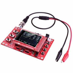
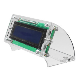
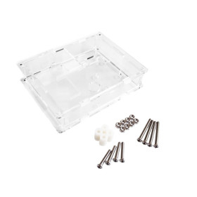
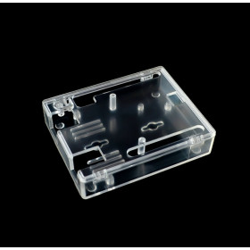
DSO138 Acrylic Case, Transparent, Assembly Kit, 9 Acrylic Parts
The acrylic case for the DSO138 oscilloscope protects the board and components during use and transport, has a transparent design for quick visibility of the display and connections, is light and rigid for stable mounting, gives easy access to the buttons and ports, assembles simply and keeps the equipment clean and tidy.
Buying this product earns you 1.78 RON in loyalty points.

International fast shipping within EU. Free Shipping for orders above 100 EUR in most EU countries.

We ship from our stock within 24H

You earn points with every order, worth 5%.
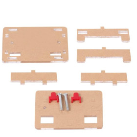
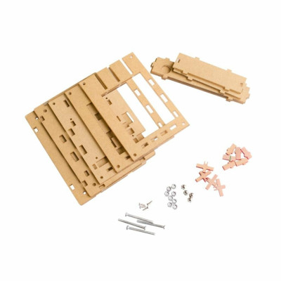
The acrylic case for the DSO138 oscilloscope is an assembly kit made of laser-cut acrylic plates, screws, nuts, extensions for the slide switches and caps for the buttons. It encloses the oscilloscope board and the LCD display in a compact body, protects the components from dust, accidental touches and short circuits on the workbench, and leaves the screen visible. It is suitable for everyday use in the workshop, for transport and for assembled and functional DSO138 oscilloscopes.
The case body is built from acrylic layers that are stacked on top of each other and tightened with four long screws passed through the holes in the corners. One layer is fixed to the back of the LCD display with four small screws and their nuts, two identical frames with the screen window and the top plate with cutouts are placed over it, and the sides are joined together. The bottom plate is held by the domed nuts at the ends of the long screws.
The main features include the window for the LCD screen, the cutouts for the five buttons and for the CPL, SEN1 and SEN2 slide switches, the cross-shaped caps that bring the buttons up to the surface of the case, the rectangular switch extensions and the holes in the top plate, which are smaller than the head of the crosses and prevent the buttons from coming out of the case. The kit contains no electronic components and does not require a power supply.
Specifications:
Material: Acrylic
Color: Transparent, after removing the protective films
Compatibility: DSO138 oscilloscope
Acrylic parts: 9, with windows and cutouts for the screen, buttons and switches
Long screws: 4, for tightening the layers, with nuts and domed nuts
Small screws: 4, with nuts, for fixing the LCD display
Switch extensions: 3, for CPL, SEN1 and SEN2
Button caps: Cross-shaped, for OK, +, -, SEL and reset
Layout:
| Element | Function |
|---|---|
| Maze-pattern layer | Mounted on the back of the LCD display with the four small screws and their nuts. Holds the display fixed in the case. |
| Two identical frames with the screen window | Placed over the maze-pattern layer. They form the upper part of the body and leave the LCD screen visible. |
| Top plate | Covers the assembly and has cutouts for the buttons and slide switches. The button holes are smaller than the head of the crosses, so the caps cannot come out. |
| Bottom plate | Closes the case at the bottom and is held by the domed nuts at the ends of the long screws. |
| Sides | Joined to each other and to the case layers, closing the body at the edges. |
| Cross-shaped caps | Extend the OK, +, -, SEL and reset buttons of the board up to the surface of the case. Press the cap and the pressure reaches the button. |
| CPL switch extension | Actuates the slide switch that selects the coupling mode of the input signal, in the GND, DC and AC positions. |
| SEN1 and SEN2 switch extensions | Actuate the slide switches that set the vertical sensitivity, that is, the voltage per division. |
| Long screws with nuts | Pass through the corner holes and tighten the top layer, then fix the main oscilloscope board. |
| Small screws with nuts | Fix the LCD display to the acrylic layer mounted on its back. |
| Domed nuts | Screwed onto the ends of the long screws, at the bottom, and hold the bottom plate. |
Usage:
Take the assembly out of the parts bag and remove the protective films from the acrylic plates, on a sheet of paper towel, so as not to scratch the surfaces or trap fingerprints between the layers.
Remove the rubber feet of the oscilloscope board and the support section of the board that does not fit into the case. If the section is designed to break off, it comes off easily by hand.
First check, without nuts, how the parts fit together. A trial assembly shows the role of each layer and avoids later disassembly.
Mount the maze-pattern layer on the back of the LCD display with the four small screws and their nuts, tightening by hand only. Keep the display straight, because a tilted mounting is only noticed at the end.
Place the two identical frames over the maze-pattern layer, then the top plate. Insert the CPL, SEN1 and SEN2 switch extensions into the side cutouts and the cross-shaped caps into the button holes, with the arms of the cross oriented normally when the oscilloscope is viewed from the front.
Pass the four long screws through the corner holes and screw on four nuts to hold the top layer, still by hand.
Join the main board with the LCD display. Align the display connectors, the screws and the switches, and the switch handles must enter between the legs of the extensions. Press evenly until the connectors fully engage.
Power the oscilloscope before the final closing and check that it starts. Set CPL to GND, the recommended starting position until a probe is connected, then choose the SEN1 and SEN2 positions according to the measured signal. The extensions must move easily, without catching on the edges of the cutouts.
Press each cap in turn. OK stops the image on the screen and resumes it on the second press, SEL selects the parameter to change, + and - change its value, and the reset button restarts the oscilloscope.
Fix the main board with four nuts, then mount the sides and the bottom plate and tighten the domed nuts. Tighten by hand only, without a wrench and without force, because the acrylic cracks when tightened unevenly and the circuit board can bend.
Do not cut or break pieces out of the acrylic to make room for cables, because the material is fragile. If you need a larger opening, use a fine-tooth saw.
Produs destinat utilizarii in proiecte electronice, automatizari, prototipare, educatie si cercetare.
Produsul trebuie utilizat numai conform specificatiilor tehnice mentionate in descriere si/sau in documentatia produsului.
Avertismente generale de siguranta:
Nu utilizati produsul la tensiuni, curenti sau temperaturi peste valorile specificate.
Montajul si conectarea trebuie realizate de persoane cu cunostinte tehnice minime in domeniul electric/electronic.
Evitati scurtcircuitele, inversarea polaritatii si conectarea gresita a alimentarii.
Nu lasati produsul alimentat nesupravegheat in timpul testelor.
Produsul nu este jucarie si nu este destinat copiilor.
Pentru modulele electronice, se recomanda utilizarea in carcase, panouri sau montaje protejate, dupa caz.
Identificare produs:
Denumirea produsului, codul/SKU-ul si caracteristicile tehnice sunt mentionate in pagina produsului si/sau pe eticheta ambalajului.
Producator / Importator / Distribuitor:
Sigmanortec S.R.L.
Calea Bucuresti nr. 9, Targu Jiu, Gorj, Romania
E-mail: [email protected]
Website: www.sigmanortec.ro
Persoana responsabila in UE:
Sigmanortec S.R.L.
Calea Bucuresti nr. 9, Targu Jiu, Gorj, Romania
E-mail: [email protected]
Documentatie si siguranta:
Pentru informatii suplimentare, fise tehnice, declaratii de conformitate sau instructiuni, ne puteti contacta la [email protected].
Reviews (4) - Review moderation

... dar am avut mari probleme sa o aamperecheza cu montajul. Gaurile nu se suprapun peste cele ale placii de osciloscop (exista un decalaj de vreo 2 mm!) si a fost nevoie sa le atraga prin frezare ca sa pot termina montajul. Unul dintre auruburi a venit stramb din fabrica, parca sa-mi faca an ciuda, nu era de ajuns prima neconcordanaa...rnSa nu mai spun ca nu are absolut niciun fel de schema de montaj - iar ce gasisi pe YT sunt chestii ce se bat cap an cap, fiecare cu versiunea lui.
Foarte buna
Buna dar a venit cu piese crapate si rupte.... Noroc cu adezivi rapizi
Mai demult, am comandat un kit osciloscop. L-am construit. Mi-a iesit din prima. Nu-mi venea sa cred. DOream o carcasa pentru osciloscop. Am trimis un e-mail. Raspuns prompt. Am comandat carcasa. Am primit-o prompt. Mi-am cam agaaat urechile an piesele primite, aaa ca ... email, raspuns prompt cu trimitere la un videoclip si ... carcasa a iesit. Am un aparat dragua si funcsional. Multumesc. Celelalte piese comandate mai aateapta ... sa vina primavara ca sa pot lucra an atelier, afara ...
The acrylic case for the DSO138 oscilloscope is a kit of transparent plates, screws, nuts, switch extensions and button caps that encloses the oscilloscope board and the LCD display in a compact body. It protects the components from dust, accidental touches and short circuits on the workbench, while the windows and cutouts keep the screen in view and allow the use of the buttons and sliding switches.
The case is not an electronic module. The tutorial explains the assembly part by part and the first test of the oscilloscope after mounting, based on a DSO138 oscilloscope that is already assembled and working.

How it works:
The case is made of several laser-cut acrylic layers that are stacked on top of each other and tightened with four long screws passed through the holes in the corners. One layer is fixed to the back of the LCD display with the small screws and their nuts. Two identical frames with the screen window and the top plate with cutouts for buttons and switches are placed over it. The sides join together, and the bottom plate is held by the domed nuts at the ends of the long screws.
The small cross-shaped pieces extend the buttons on the board up to the surface of the case. The rectangular pieces extend the sliding switches. The top plate has holes smaller than the head of the crosses, so the buttons cannot come out when the case is assembled correctly.
Acrylic withstands even pressure well, but it is fragile under uneven tightening and when cut. For this reason the nuts are tightened by hand only, without a wrench and without force, otherwise the acrylic cracks or the circuit board bends.
Connection:
Nothing is connected electrically to this product. There are no pins, power supply or logic levels. The table below shows where each type of part in the kit is mounted.
| Product pin | Connects to | Role |
|---|---|---|
| Acrylic plates (layers, sides, top and bottom plate) | The DSO138 oscilloscope board and the LCD display | Forms the body of the case and protects the board |
| Long screws with nuts | The holes in the corners of the plates | Tighten the top layer and fix the main board |
| Small screws with nuts | The holes of the layer mounted on the back of the LCD | Fix the display to the acrylic layer |
| Domed nuts | The ends of the long screws, at the bottom | Hold the bottom plate and close the assembly |
| Cross-shaped caps | The buttons on the board | Bring the buttons up to the surface of the case |
| Rectangular switch extensions | The sliding switches on the board | Allow the switches to be operated through the cutouts in the top plate |
Buttons, controls and indicators:
The case has no buttons of its own, nor LEDs or a display. The caps in the kit transfer the actuation to the oscilloscope's controls, and the acrylic window keeps the screen visible.
| Element | What it does | How to use it |
|---|---|---|
| Cross caps (OK, +, -, SEL and the reset button) | Extend the five buttons of the board | Press on the surface of the case. OK stops the image on the screen and resumes it on the second press, SEL selects the parameter to change, and + and - change its value. The reset button restarts the oscilloscope. |
| CPL switch extension | Selects the coupling mode of the input signal | Move between the GND, DC and AC positions. GND connects the input to ground, DC leaves the signal unchanged, and AC removes the DC component. |
| SEN1 and SEN2 switch extensions | Set the vertical sensitivity, that is the voltage per division | Move between positions, and the current setting appears in the bottom left corner of the screen. |
| Screen window | Keeps the LCD display in view | During the test, check that no part covers the screen and that the image is not tilted. |
For the sliding switches, the recommended starting position is CPL on GND, until a probe is connected. The SEN1 and SEN2 positions are chosen according to the signal being measured. During the test, check that the extensions move smoothly between positions, without catching on the edges of the cutouts.
For the cross-shaped caps, check that each one sits in the upright position, with the arms oriented like a cross when the oscilloscope is viewed normally. Press each button and watch the screen. If the image stops at OK and returns on the second press, the cap is working correctly.
Setup:
Here, setup means assembling the case. Follow the steps in the order below, without tightening the nuts with force.
Take the parts out of the bag and remove the protective film from the acrylic plates. Do this on a paper towel, so as not to scratch the surfaces or trap fingerprints between the layers.
Remove the rubber feet or supports that come with the oscilloscope board, and any support section of the board that does not fit inside the case. If the section is designed to be broken off, it comes off easily by hand.
First, without nuts, check how the parts fit together. A trial assembly shows the role of each layer and avoids later disassembly.
Mount the maze-patterned layer on the back of the LCD display. Pass the four small screws through its holes and tighten the nuts by hand only. Keep the display straight, because a tilted mounting is only noticed at the end.
Place the two identical frames with the screen window over the maze layer, then the top plate with the cutouts for buttons and switches. Insert the switch extensions into the side cutouts and the cross caps into the button holes.
Pass the four long screws through the corner holes and screw on four nuts to hold the top layer. Tighten by hand only.
Join the main board with the LCD display. Align the display connectors, the screws and the switches, and the switch levers must fit between the legs of the extensions. Press evenly until the connectors go fully in. Check that everything is aligned before pressing.
Power on the oscilloscope and check that it starts and that the buttons and switches respond. If everything works, fix the main board with four nuts, tightening by hand only.
Mount the sides, which join together, then the bottom plate. Tighten the four domed nuts at the ends of the long screws, again by hand. You do not need any settings to be kept, because the case has no memory or parameters.
Usage example:
After assembly, place the oscilloscope with the screen facing you and move CPL to GND. Power on the oscilloscope and wait for the image to appear on the screen. The baseline should be straight, and the whole screen should be visible through the window, with no corners covered.
Press OK and check that the image stays frozen, then press OK again to resume the display. Press SEL, change the parameter value with + and -, and watch the change on the screen. At the end, press the reset button and check that the oscilloscope restarts.
Connect the probe, move CPL to DC or AC, choose the appropriate SEN1 and SEN2 positions, and measure a signal, for example the oscilloscope's calibration signal. If the image is stable and the switches do not catch, the case is mounted correctly.
Common problems:
The LCD display appears tilted in the window. The cause is mounting the maze layer with the display crooked. The solution is to take the assembly apart and remount the display straight before tightening the nuts.
A button does not respond or stays pressed. The usual cause is a cross cap fitted upside down or stuck in its hole. Remove the cap and fit it in the upright position, with the arms of the cross oriented normally.
A sliding switch moves stiffly. The cause is a misaligned extension, with the switch lever outside its legs, or a nut that is too tight. Reseat the extension and loosen the nuts.
The oscilloscope does not power on after assembly. The cause is usually a display connector that has not fully engaged, or a board bent by over-tightened nuts. Reseat the connectors by pressing evenly and loosen the nuts.
The acrylic has cracked. The cause is tightening with force or a cut made in the material, because acrylic is fragile. Tighten by hand only and do not cut parts out of the plates.
The wires or power jack do not fit under the case. The cutouts are made for the standard configuration of the board, so route the cables through the existing openings.
Limitations and tips:
The case is made for the DSO138 oscilloscope and is not universal. Acrylic does not withstand uneven tightening, strong impacts or cuts, and the case protects the board from dust and accidental short circuits, not from heavy shocks.
For a clean finish, remove the films and wipe off fingerprints before the final closing, because they stay trapped between the layers. If the oscilloscope is used in environments with vibrations, you can lock the nuts with a drop of low-strength thread locker.