
Product images are for informational purposes only and may vary slightly depending on the batch and supplier. Product specifications and prices may be subject to change without notice. We do our best to provide accurate and complete product specifications, but they may not be completely accurate. If you encounter any such situation, please let us know.
The product is intended for specialists and requires qualified and authorized personnel. The product does not include assembly/use instructions . Putting the product into operation by unqualified persons leads to the loss of the warranty according to the Terms and Conditions on the site.
The specified technical parameters (current, power, etc.) represent maximum allowable values under ideal operating conditions. For safe use and optimal lifespan, it is recommended to operate the product continuously at no more than 50% of the specified maximum values.
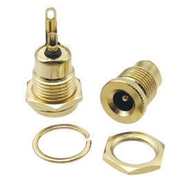
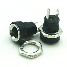
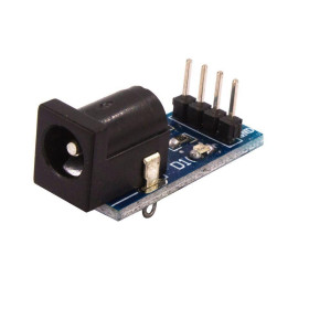
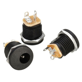
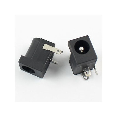
Female PCB DC Power Connector DC-005, 5.5x2.1mm, 3 pins, 30V, 1A
5.5x2.1 mm female PCB jack with 3 pins, ideal for quickly creating power inputs on electronic boards and Arduino projects. It mounts directly on the PCB by soldering, provides a stable connection for standard DC adapters, ensures a secure contact through its robust construction and is suitable for prototyping and repairs in low voltage applications.
Buying this product earns you Ft5.51 in loyalty points.

International fast shipping within EU. Free Shipping for orders above 100 EUR in most EU countries.

We ship from our stock within 24H

You earn points with every order, worth 5%.
The DC-005 female connector is a power jack for mounting on a printed circuit board, into which the plug of a mains adapter with an outer diameter of 5.5 mm and a centre pin of 2.1 mm is inserted. It is used to bring DC voltage from an external adapter to a dedicated circuit, a test board or a user-built device, at voltages of up to 30 VDC.
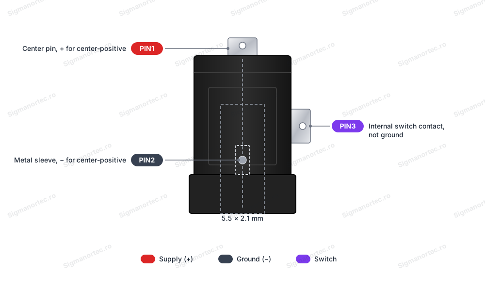
The jack has three solder contacts: the centre pin for the active pole of the plug, a side contact for the metal sleeve and a third contact that belongs to an internal switch, actuated mechanically when the plug is inserted. The rated current is 1 A, and the black plastic body has compact dimensions, suited to small circuits.
The main features include through-hole soldering onto the PCB, the front opening for 5.5 x 2.1 mm plugs, the internal switch contact that can signal the presence of the plug and a simple construction that is easy to replace. It is commonly used with mains adapters with positive centre polarity.
Specifications:
Maximum voltage: 30 VDC
Maximum current: 1 A
Model: DC-005
Type: Female PCB mount jack
Plug outer diameter: 5.5 mm
Centre pin diameter: 2.1 mm
Number of contacts: 3
Extra: Internal switch contact (PIN3)
Colour: Black
Dimensions: 14.2 x 9 x 15.1 mm
Pinout:
| Connector | Pin | Function |
|---|---|---|
| DC-005 | PIN1 | Centre pin, positive for adapters with positive centre polarity |
| DC-005 | PIN2 | Metal sleeve, negative for adapters with positive centre polarity |
| DC-005 | PIN3 | Internal switch contact, not ground |
Usage:
Identify the pins before soldering, as their position may differ slightly from one batch to another. Insert a 5.5 x 2.1 mm plug into the jack without connecting it to the mains, set the multimeter to continuity and place one probe on the tip of the plug and the other on each pin of the connector. The pin with which the multimeter beeps is PIN1.
Repeat the measurement with one probe on the metal body of the plug to find PIN2. The remaining pin is PIN3, the internal switch contact.
Solder the connector to the test board or PCB before inserting the plug, using a short contact at each pin, as the plastic body can deform if it gets too hot.
Connect PIN1 to the positive of the circuit and PIN2 to its negative. Leave PIN3 unconnected if you do not need the switch.
Check the polarity symbol on the adapter before connecting it and use only adapters with positive centre polarity. Do not apply a voltage higher than 30 VDC and do not exceed a current of 1 A.
To check the operation of the switch, measure the continuity between PIN3 and the other two pins, first without the plug and then with the plug inserted. The pin with which the state changes is the switch pair.
- Dimensions
- 14.2 x 9 x 15.1 mm
- Model
- DC-005
- Type
- Female socket for PCB mounting
- Colour
- Black
- Number of pins
- 3
- Maximum current
- 1 A
- Outer diameter
- 5.5 mm
- Maximum voltage
- 30 V DC
Produs destinat utilizarii in proiecte electronice, automatizari, prototipare, educatie si cercetare.
Produsul trebuie utilizat numai conform specificatiilor tehnice mentionate in descriere si/sau in documentatia produsului.
Avertismente generale de siguranta:
Nu utilizati produsul la tensiuni, curenti sau temperaturi peste valorile specificate.
Montajul si conectarea trebuie realizate de persoane cu cunostinte tehnice minime in domeniul electric/electronic.
Evitati scurtcircuitele, inversarea polaritatii si conectarea gresita a alimentarii.
Nu lasati produsul alimentat nesupravegheat in timpul testelor.
Produsul nu este jucarie si nu este destinat copiilor.
Pentru modulele electronice, se recomanda utilizarea in carcase, panouri sau montaje protejate, dupa caz.
Identificare produs:
Denumirea produsului, codul/SKU-ul si caracteristicile tehnice sunt mentionate in pagina produsului si/sau pe eticheta ambalajului.
Producator / Importator / Distribuitor:
Sigmanortec S.R.L.
Calea Bucuresti nr. 9, Targu Jiu, Gorj, Romania
E-mail: [email protected]
Website: www.sigmanortec.ro
Persoana responsabila in UE:
Sigmanortec S.R.L.
Calea Bucuresti nr. 9, Targu Jiu, Gorj, Romania
E-mail: [email protected]
Documentatie si siguranta:
Pentru informatii suplimentare, fise tehnice, declaratii de conformitate sau instructiuni, ne puteti contacta la [email protected].
Reviews (9) - Review moderation

Folosite la incarcare acumulatoare
F.BUN
Super
Am primit exact produsul comandat..Produs de calitate
SUPER!!!
The DC-005 female connector, 5.5 x 2.1 mm, 3 pins, is the power socket that accepts the plug of a mains adapter with positive on the centre. Use it to bring power from an external adapter onto your own circuit, a test board or a device you have built.
This tutorial does not use any development board and has no program. We power up the connector with a 12 VDC 1 A adapter, a 1 kΩ resistor and a 5 mm red LED as a power-presence indicator.

How it works:
The socket has a 2.1 mm centre pin and a metal sleeve with a diameter of 5.5 mm. When the adapter plug goes into the socket, the tip of the plug touches the centre pin, and the body of the plug touches the sleeve. With an adapter that has positive on the centre, the centre pin carries the positive, and the sleeve carries the negative. PIN1 is the centre pin, that is the positive, and PIN2 is the sleeve, that is the negative.
PIN3 is the contact of an internal switch, which opens or closes mechanically when the plug is inserted. It is not ground. It can be used, for example, to disconnect an internal battery when the adapter is connected. In the test circuit below we do not use it and leave it unconnected.
The connector is rated for 30 VDC and a load current of 1 A. For the red LED, which drops about 2 V and is driven with 10 mA, the limiting resistor is calculated as follows: R = (12 V - 2 V) / 10 mA = 1 kΩ. The power dissipated by the resistor is P = 0.01 A x 0.01 A x 1000 Ω = 0.1 W, so a 0.25 W resistor is sufficient.
Connection:
Power the circuit only from a 12 VDC 1 A adapter with a 5.5 x 2.1 mm plug and positive on the centre, after you have checked the polarity symbol on the adapter label. The circuit is purely analogue, so there are no logic levels, level converter or pull-up resistors. Solder the connector to the board before inserting the plug.
| Product pin | Connects to | Role |
|---|---|---|
| PIN1 (centre) | 1 kΩ resistor, end 1 | Power positive, 12 VDC |
| 1 kΩ resistor, end 2 | Anode of the 5 mm red LED (long leg) | Limits the LED current to about 10 mA |
| LED cathode (short leg) | PIN2 (sleeve) | Return to negative |
| PIN3 (switch) | Unconnected | Internal switch contact, not used in this test |
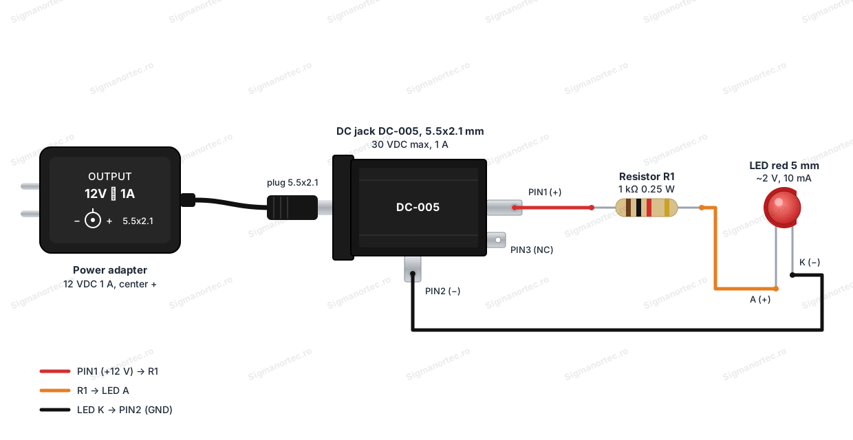
The pin positions differ slightly from one batch to another. In general, the wide tab at the back is PIN1, but checking with the multimeter described in the Configuration section is mandatory.
Buttons, adjustments and indicators:
The connector has no buttons, potentiometers or LEDs of its own. The only element that reacts to actuation is the contact of the internal switch, and in the test circuit an external LED is added.
| Element | What it does | How to use it |
|---|---|---|
| PIN3 (switch contact) | Opens or closes when the plug is inserted into the socket | Measure with the multimeter on continuity, with the plug removed and then inserted. If you do not need it, leave it unconnected |
| 5 mm red LED (external) | Shows that voltage is present between PIN1 and PIN2 | Lights continuously when the adapter is connected and the polarity is correct |
To see how the switch works, set the multimeter to continuity, place one probe on PIN3 and the other on each of the other two pins, first without the plug. Note which pin it beeps to. Then insert the plug, with no adapter connected to the mains, and repeat the measurement. The pin where the state changes is the switch pair.
Configuration:
The connector has no operating modes, settings or memory, but a quick check before soldering avoids polarity mistakes.
Set the multimeter to continuity. Insert a 5.5 x 2.1 mm plug into the socket, without connecting it to the mains. Place one probe on the centre tip of the plug and the other on each pin of the connector, one at a time. The pin the multimeter beeps to is PIN1.
Repeat with one probe on the metal body of the plug, to find PIN2. The remaining pin is PIN3, that is the switch.
| Pin | Contact | Use in the test |
|---|---|---|
| PIN1 | Centre, positive | To the 1 kΩ resistor |
| PIN2 | Sleeve, negative | To the LED cathode |
| PIN3 | Switch | Unconnected |
Solder quickly, with a short contact at each pin, because the plastic body can deform if it gets too hot.
Usage example:
The example is a power-presence indicator for 12 VDC. Solder the connector to the test board. Solder the 1 kΩ resistor between PIN1 and the anode of the 5 mm red LED. The anode is the longer leg of the LED. Solder the cathode, the shorter leg, to PIN2. Leave PIN3 unconnected.
Check the polarity of the LED and of the adapter once more, then insert the plug of the 12 VDC 1 A adapter into the socket. The LED should light continuously. About 10 mA flows through the circuit, so the connector is loaded far below the 1 A limit, and the 0.25 W resistor remains at most slightly warm.
If you remove the plug, the LED goes out immediately. This shows that each contact works correctly. The same socket can then power the real circuit, with a load current of at most 1 A.
Common problems:
The LED does not light. The usual cause is an LED fitted in reverse, or an adapter with reversed polarity, with positive on the sleeve. Check the polarity symbol on the adapter, reverse the LED and check that the resistor is in series with it.
The LED does not light and the polarity is correct. Most likely one of the pins was soldered wrongly. Measure with the multimeter on continuity to identify PIN1, PIN2 and PIN3, and redo the solder joints.
The LED flickers or lights only when you move the plug. The plug may have the wrong inner diameter, for example 2.5 mm instead of 2.1 mm, or a solder joint is cold. Check the size of the plug and resolder the contacts.
The connector body is deformed or melted around the pins. Soldering took too long or the iron was too hot. Use a short contact at each pin and replace the connector if the plastic has deformed.
Limitations and tips:
The connector is rated for at most 30 VDC and 1 A. For sources with higher current, use a connector rated for that current. It is not suitable for mains voltage.
The socket accepts only 5.5 x 2.1 mm plugs. The polarity is not imposed by the connector but by the adapter, so always check the polarity symbol before connecting. For projects that could be powered incorrectly, add a series diode or reverse polarity protection after the socket.
Contact PIN3 can further be used to switch an internal source, such as a battery, at the moment the external adapter is connected.