
Product images are for informational purposes only and may vary slightly depending on the batch and supplier. Product specifications and prices may be subject to change without notice. We do our best to provide accurate and complete product specifications, but they may not be completely accurate. If you encounter any such situation, please let us know.
The product is intended for specialists and requires qualified and authorized personnel. The product does not include assembly/use instructions . Putting the product into operation by unqualified persons leads to the loss of the warranty according to the Terms and Conditions on the site.
The specified technical parameters (current, power, etc.) represent maximum allowable values under ideal operating conditions. For safe use and optimal lifespan, it is recommended to operate the product continuously at no more than 50% of the specified maximum values.
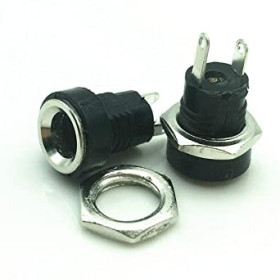
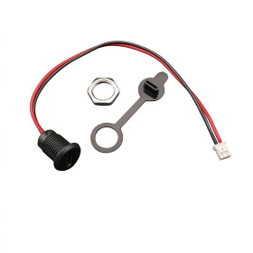
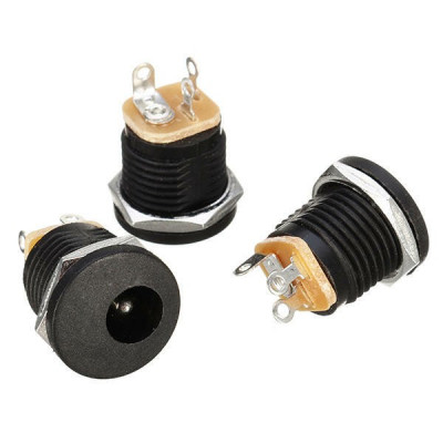
DC 5.5x2.1 Female Power Jack, Panel Mount, 14mm Hole, 3 Solder Lugs
5.5x2.1 female DC power jack for power supply, ideal for electronics projects and industrial equipment. Mounts on a panel with hole fixing for a stable fit, requires a 14 mm hole, offers firm contact and reliable connection, suitable for quick wiring and easy maintenance.
Shipping by Wednesday 11 November
Buying this product earns you 0.08 RON in loyalty points.

International fast shipping within EU. Free Shipping for orders above 100 EUR in most EU countries.

We ship from our stock within 24H

You earn points with every order, worth 5%.
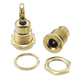
The DC 5.5 x 2.1 mm female power jack with panel mount is a connector that is fitted into a hole in the enclosure of a device or into a front panel. It receives the power supply from an external adapter with a 5.5 x 2.1 mm plug, without cables having to pass directly through the wall of the box. It is suitable for laboratory supplies, amplifiers, LED strips, fans, video cameras and other devices mounted in enclosures.
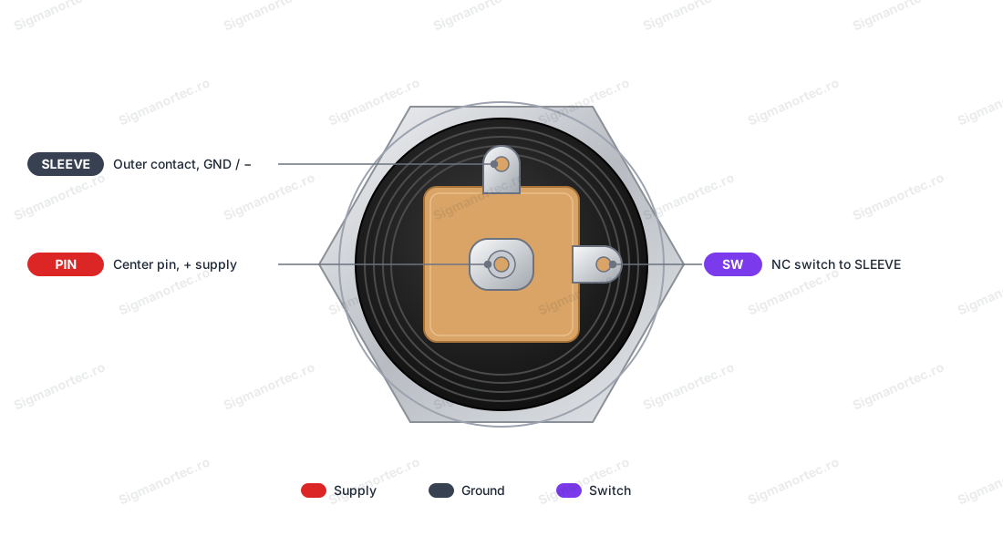
The jack accepts plugs with an outer diameter of 5.5 mm and an inner diameter of 2.1 mm. It is fixed in a hole with a diameter of 14 mm, using the threaded body and the hexagonal nut. On the back it has three solder lugs. PIN is connected to the centre pin, SLEEVE to the outer wall of the jack, and SW is a switching contact.
The main features include the black plastic body with external thread, the metal hexagonal nut for fixing in the panel, the centre pin for the positive supply, the outer contact for ground, the switching contact SW and the three lugs with holes for soldering the wires. The jack has no power of its own, it transmits the DC voltage of the adapter to the load.
Specifications:
Type: DC power female jack, for panel mounting
Compatible plug: 5.5 x 2.1 mm (outer diameter 5.5 mm, inner diameter 2.1 mm)
Contacts: 3 solder lugs (PIN, SLEEVE, SW)
Fixing: Threaded body with hexagonal nut
Mounting hole diameter: 14 mm
Colour: Black
Layout:
| Element | Function |
|---|---|
| Front opening with centre pin | Receives the plug of the power adapter. The centre pin enters the 2.1 mm inner hole of the plug. |
| Threaded body | Passes through the 14 mm hole in the panel and supports the fixing nut. |
| Hexagonal nut | Is tightened from the back of the panel and fixes the jack in the hole. |
| PIN lug | The contact connected to the centre pin. By convention it is used as the positive supply. |
| SLEEVE lug | The contact connected to the outer wall of the jack, which touches the sleeve of the plug. It is used as negative or ground. |
| SW lug | Switching contact. It touches the SLEEVE lug while no plug is inserted, and separates from it when the plug enters the jack. |
| Insulating base | Electrically separates the lugs from each other and supports them at the back of the jack body. |
Pinout:
| Connector | Pin | Function |
|---|---|---|
| DC 5.5 x 2.1 jack | PIN | Centre pin, positive supply by convention |
| DC 5.5 x 2.1 jack | SLEEVE | Outer contact, negative or ground |
| DC 5.5 x 2.1 jack | SW | Switching contact, connected to SLEEVE without a plug and open when a plug is inserted |
Usage:
Do not use the jack for the 220 VAC mains voltage, it is intended for low-voltage DC power supplies.
Nothing is marked on the jack, so identify the lugs before soldering. Set the multimeter to continuity measurement and, with no plug in the jack, find the SW lug, which is connected to SLEEVE.
Then insert a 5.5 x 2.1 mm plug and measure between the inner tip of the plug and each lug. The lug that connects to the centre pin is PIN, and the one that connects to the sleeve of the plug is SLEEVE.
Drill the panel with a 14 mm drill bit, insert the jack from the front of the panel and tighten the nut from the back without forcing the thread.
Slide a piece of heat-shrink tubing onto each wire, solder the positive wire to PIN and the negative wire to SLEEVE, then check that the solder does not bridge two lugs and insulate each joint.
Check the label of the power adapter before connecting. Most adapters have positive on the centre, and a reversed supply can destroy the load.
Insert the plug into the jack, connect the adapter to the mains socket and measure the voltage with the multimeter on DC volts, with the red probe on PIN and the black probe on SLEEVE. A positive value, close to the voltage of the adapter, shows that the polarity is correct.
Do not use plugs with a 2.5 mm inner diameter, because they fit loosely and make poor contact.
Keep the load current as low as possible, below 1 A, and preferably below 0.5 A for safety. For higher currents choose a connector of suitable rating.
- Type
- Female DC power socket, panel mount
- Colour
- Black
- Number of pins
- 3
- Connector type
- 5.5 x 2.1 mm
- Mounting
- Panel mount, with thread and nut
- Mounting hole diameter
- 14 mm
Produs destinat utilizarii in proiecte electronice, automatizari, prototipare, educatie si cercetare.
Produsul trebuie utilizat numai conform specificatiilor tehnice mentionate in descriere si/sau in documentatia produsului.
Avertismente generale de siguranta:
Nu utilizati produsul la tensiuni, curenti sau temperaturi peste valorile specificate.
Montajul si conectarea trebuie realizate de persoane cu cunostinte tehnice minime in domeniul electric/electronic.
Evitati scurtcircuitele, inversarea polaritatii si conectarea gresita a alimentarii.
Nu lasati produsul alimentat nesupravegheat in timpul testelor.
Produsul nu este jucarie si nu este destinat copiilor.
Pentru modulele electronice, se recomanda utilizarea in carcase, panouri sau montaje protejate, dupa caz.
Identificare produs:
Denumirea produsului, codul/SKU-ul si caracteristicile tehnice sunt mentionate in pagina produsului si/sau pe eticheta ambalajului.
Producator / Importator / Distribuitor:
Sigmanortec S.R.L.
Calea Bucuresti nr. 9, Targu Jiu, Gorj, Romania
E-mail: [email protected]
Website: www.sigmanortec.ro
Persoana responsabila in UE:
Sigmanortec S.R.L.
Calea Bucuresti nr. 9, Targu Jiu, Gorj, Romania
E-mail: [email protected]
Documentatie si siguranta:
Pentru informatii suplimentare, fise tehnice, declaratii de conformitate sau instructiuni, ne puteti contacta la [email protected].
Reviews (10) - Review moderation

Foarte multumit de calitatea serviciilor Dumneavoastra,de produse si de livrare.Voi apela cu incredere din nou cand va fi cazul.Multumesc!
De calitate
Inca nu le-am folosit
Produs exact ce este in descriere si pe poze.
Ok
The DC 5.5 x 2.1 mm panel mount female power jack is a connector that is mounted in a 14 mm hole, on the enclosure of a device or on a front panel. It takes power from an external power supply with a 5.5 x 2.1 mm plug, and the cables no longer pass directly through the wall. You can use it on laboratory power supplies, amplifiers, LED strips, fans, video cameras and other devices mounted in boxes.
The tutorial uses the jack on its own, as a passive connector, with a 12 VDC 1 A mains adapter and a 12 VDC fan. It shows how to identify the lugs, how to mount the jack in the panel, how to wire it and how to test it.

How it works:
The jack has three solder lugs on the back. The PIN lug is connected to the centre pin, which enters the inner hole of the plug, and by convention it is used as positive. The SLEEVE lug is connected to the outer wall of the jack, which touches the sleeve of the plug, and it is used as negative or ground. The SW lug is a switching contact that touches SLEEVE while no plug is inserted and separates from it when the plug goes in. In this tutorial the SW lug is not used.
The jack accepts plugs with an outer diameter of 5.5 mm and an inner diameter of 2.1 mm. A 2.5 mm plug fits loosely and makes poor contact, so do not use it.
The jack does not change the voltage, it only carries the current from the power supply to the load. The limit is set by the contacts, so the usual power calculations still apply. A 12 VDC fan that draws 0.15 A has a power of 12 V x 0.15 A = 1.8 W. A 12 VDC 1 A power supply can deliver at most 12 V x 1 A = 12 W. The example therefore has a large margin. Keep the load below 1 A, and for safety preferably below 0.5 A, because the exact current rating of this model is not specified.
Most power supplies have positive polarity on the centre, marked on the label with the centre positive polarity symbol. Check the power supply label before connecting, because a reversed supply can destroy the load.
Connection:
Do not use the jack for 220 VAC mains voltage, and wire it only with the power supply unplugged from the outlet. The 12 VDC fan connects to the jack, and the 12 VDC power supply with a 5.5 x 2.1 mm plug, positive on the centre, is inserted into the jack. The red wire of the fan goes to PIN, and the black wire to SLEEVE.
| Jack pin | Connects to | Role |
|---|---|---|
| PIN | 12 V fan, red wire | Power positive, centre pin |
| SLEEVE | Fan, black wire | Ground, power negative |
| SW | Not connected | Switching contact, not used in this example |
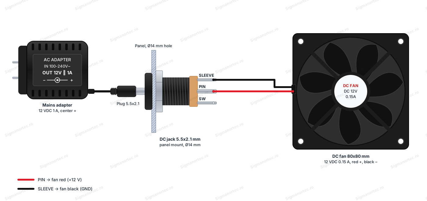
The supply voltage is that of the power supply, 12 VDC in the example. There are no logic levels, and no converter or resistors are needed. The load current must stay below 1 A, and for safety preferably below 0.5 A.
Configuration:
The jack has no buttons, adjustments or LEDs, so there are no settings to make. The preparation consists of identifying the lugs and mounting the jack in the panel.
Nothing is printed on the jack, so identify the lugs before soldering. Set the multimeter to continuity measurement. Without a plug in the jack, find the SW lug, which is connected to SLEEVE. Then insert a 5.5 x 2.1 mm plug and measure between the inner tip of the plug and each lug. The lug that leads to the centre pin is PIN. The lug that leads to the sleeve of the plug is SLEEVE. The remaining lug is SW, and its connection to SLEEVE is broken when the plug is inserted.
Drill the panel with a 14 mm drill bit. Insert the jack from the front of the panel and tighten the nut on the back, without forcing the thread.
Slide a piece of heat shrink tubing onto each wire. Solder the red wire to PIN and the black wire to SLEEVE. Check that the solder does not bridge two lugs, then insulate each joint with heat shrink tubing.
Before connecting the load, insert the plug of the power supply into the jack and connect the power supply to the outlet. Measure with the multimeter set to DC volts, with the red probe on PIN and the black probe on SLEEVE. You should read approximately +12 V. If the value is negative, the power supply has reversed polarity and you must swap the wires or the power supply. Unplug the power supply from the outlet and only then connect the fan.
Usage example:
Power an 80 x 80 mm, 12 VDC, 0.15 A fan through a jack mounted on the panel of a box. Connect the 12 VDC 1 A power supply to the jack, then plug the power supply into the outlet. The fan starts immediately, and removing the plug stops it.
If the fan does not start, disconnect the power supply and check the wire colours and the solder joints. Do not leave the plug half inserted, because an unstable contact can make the fan start and stop on its own.
Common problems:
The load does not start at all. The usual cause is a wire soldered to the wrong lug, for example to SW instead of PIN. Unplug the power supply from the outlet, check the lugs with the multimeter on continuity and resolder the wire to the correct lug.
The measured voltage is negative. The power supply has negative polarity on the centre, or the wires are reversed. Do not connect the load. Replace the power supply with one that has positive polarity on the centre, or reverse the wires at the solder joints.
The load starts and stops when you move the cable. The plug does not have an inner diameter of 2.1 mm, for example it is 2.5 mm, or the solder joint is weak. Use a 5.5 x 2.1 mm plug and resolder the joints.
The power supply shuts down or overheats. There is a short circuit between two lugs, usually a solder bridge, or the load draws more current than the power supply can deliver. Unplug the power supply from the outlet, inspect the solder joints and check the load current.
The jack turns in the panel or comes loose. The nut is not tight enough, or the hole is larger than 14 mm. Tighten the nut on the back, without forcing the thread.
Limitations and tips:
The jack is suitable for low voltage DC power supplies and small loads. Do not use it for 220 VAC mains voltage. The exact current rating of this model is not specified, so keep the load below 1 A, preferably below 0.5 A, and for higher loads choose a connector rated for that current.
Choose panels with a thickness that suits the length of the thread, so that the nut tightens fully. For a clean installation, use wires with a cross-section suitable for the load and heat shrink tubing on every joint. The jack can be used with any device powered from DC through an external power supply with a 5.5 x 2.1 mm plug, positive on the centre.