

Product images are for informational purposes only and may vary slightly depending on the batch and supplier. Product specifications and prices may be subject to change without notice. We do our best to provide accurate and complete product specifications, but they may not be completely accurate. If you encounter any such situation, please let us know.
The product is intended for specialists and requires qualified and authorized personnel. The product does not include assembly/use instructions . Putting the product into operation by unqualified persons leads to the loss of the warranty according to the Terms and Conditions on the site.
The specified technical parameters (current, power, etc.) represent maximum allowable values under ideal operating conditions. For safe use and optimal lifespan, it is recommended to operate the product continuously at no more than 50% of the specified maximum values.
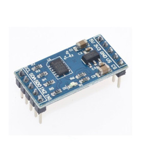
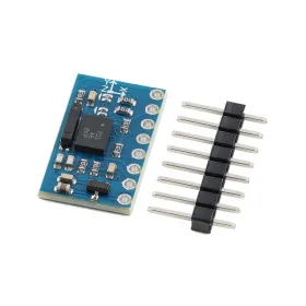
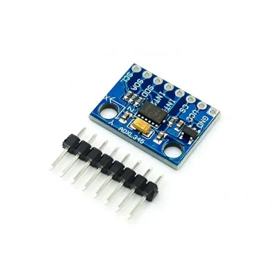
GY-291, ADXL345 3-axis sensor module
The ADXL345 3-axis accelerometer module is ideal for Arduino projects and other development boards, providing precise acceleration measurement and vibration detection, useful in stabilizing and maintaining the balance of robots. It operates at 3-5VDC, communicates simply via I2C, has a compact form factor for quick integration and good response to fine movements.
Shipping by Thursday 22 October
Buying this product earns you 1.55 RON in loyalty points.

International fast shipping within EU. Free Shipping for orders above 100 EUR in most EU countries.

We ship from our stock within 24H

You earn points with every order, worth 5%.
The GY-291 module with ADXL345 sensor is a 3-axis digital accelerometer, suitable for electronic projects that require precise measurement of acceleration on the X, Y, and Z axes, vibration detection, and monitoring movement or tilt.
It is compatible with Arduino and other development boards, making it a very good choice for robots that need to maintain balance, stabilization systems, motion measurement devices, wearable applications, and prototyping projects.
The module offers 13-bit resolution, selectable measurement ranges of ±2g, ±4g, ±8g, and ±16g, as well as communication via I2C, IIC, and SPI, allowing easy integration into numerous applications. Low power consumption and stable operation recommend it for both simple setups and more complex projects in robotics and automation.
Specifications:
Supply voltage: 3-5VDC
Sensor operating voltage: 2.0V - 3.6V
Model: GY-291
Chip: ADXL345
Sensor type: 3-axis digital accelerometer
Measured axes: X, Y, Z
Communication interface: I2C, IIC, SPI
Measurement range: ±2g, ±4g, ±8g, ±16g
Resolution: 13 bits
Frequency range: 0.1 Hz - 3.2 kHz
Power consumption: 1 uA in standby mode, 150 uA in active mode
Operating temperature: -40°C to +85°C
Compatibility: Arduino and other development boards
Dimensions: 20 x 20 mm
Pinout:
| Pin | Name | Role | Details |
|---|---|---|---|
| 1 | GND | Ground | Connects to the development board's GND |
| 2 | VCC | Power supply | The module can usually be powered at 3.3V or 5V, depending on the adapter board |
| 3 | CS | Chip Select | Used in SPI mode. For I2C it is usually connected to VCC |
| 4 | INT1 | Interrupt 1 | Output for configurable events such as motion detection or shock |
| 5 | INT2 | Interrupt 2 | Second configurable interrupt output |
| 6 | SDO | Address select / SPI data | In I2C sets the sensor address. At GND the address is 0x53, at VCC the address is 0x1D |
| 7 | SDA | I2C data line | Connects to the SDA pin of the board, for example A4 on Arduino Uno |
| 8 | SCL | I2C clock line | Connects to the SCL pin of the board, for example A5 on Arduino Uno |
Usage:
The module is used for detecting acceleration, vibrations, tilt, and movement in electronics and automation projects. It can be integrated into self-balancing robots, drones, navigation systems, wearable devices, motion-based controllers, and structural monitoring applications.
For use, the module connects to the development board via the I2C or SPI interface, respecting the recommended supply voltage and correct pin configuration. It is recommended for projects that require precise measurement of movements and orientation in real time.
Arduino Example:
| Arduino Uno | ADXL345 |
|---|---|
| GND | GND |
| 5V | VCC |
| A4 | SDA |
| A5 | SCL |
Code on the next tab.
Produs destinat utilizarii in proiecte electronice, automatizari, prototipare, educatie si cercetare.
Produsul trebuie utilizat numai conform specificatiilor tehnice mentionate in descriere si/sau in documentatia produsului.
Avertismente generale de siguranta:
Nu utilizati produsul la tensiuni, curenti sau temperaturi peste valorile specificate.
Montajul si conectarea trebuie realizate de persoane cu cunostinte tehnice minime in domeniul electric/electronic.
Evitati scurtcircuitele, inversarea polaritatii si conectarea gresita a alimentarii.
Nu lasati produsul alimentat nesupravegheat in timpul testelor.
Produsul nu este jucarie si nu este destinat copiilor.
Pentru modulele electronice, se recomanda utilizarea in carcase, panouri sau montaje protejate, dupa caz.
Identificare produs:
Denumirea produsului, codul/SKU-ul si caracteristicile tehnice sunt mentionate in pagina produsului si/sau pe eticheta ambalajului.
Producator / Importator / Distribuitor:
Sigmanortec S.R.L.
Calea Bucuresti nr. 9, Targu Jiu, Gorj, Romania
E-mail: [email protected]
Website: www.sigmanortec.ro
Persoana responsabila in UE:
Sigmanortec S.R.L.
Calea Bucuresti nr. 9, Targu Jiu, Gorj, Romania
E-mail: [email protected]
Documentatie si siguranta:
Pentru informatii suplimentare, fise tehnice, declaratii de conformitate sau instructiuni, ne puteti contacta la [email protected].
Reviews (2) - Review moderation

#include <Wire.h>
const uint8_t SENSOR_ADDR = 0x53;
const uint8_t REG_POWER_CTL = 0x2D;
const uint8_t REG_DATA_FORMAT = 0x31;
const uint8_t REG_DATAX0 = 0x32;
float accX = 0.0;
float accY = 0.0;
float accZ = 0.0;
void writeToRegister(uint8_t reg, uint8_t value) {
Wire.beginTransmission(SENSOR_ADDR);
Wire.write(reg);
Wire.write(value);
Wire.endTransmission();
}
void enableMeasurementMode() {
writeToRegister(REG_POWER_CTL, 0x08);
}
void setRangeTo2G() {
writeToRegister(REG_DATA_FORMAT, 0x00);
}
void readAcceleration(float &x, float &y, float &z) {
Wire.beginTransmission(SENSOR_ADDR);
Wire.write(REG_DATAX0);
Wire.endTransmission(false);
Wire.requestFrom(SENSOR_ADDR, (uint8_t)6);
if (Wire.available() == 6) {
int16_t rawX = Wire.read() | (Wire.read() << 8);
int16_t rawY = Wire.read() | (Wire.read() << 8);
int16_t rawZ = Wire.read() | (Wire.read() << 8);
x = rawX / 256.0;
y = rawY / 256.0;
z = rawZ / 256.0;
}
}
void setup() {
Serial.begin(9600);
Wire.begin();
enableMeasurementMode();
setRangeTo2G();
delay(20);
Serial.println("ADXL345 I2C test");
}
void loop() {
readAcceleration(accX, accY, accZ);
Serial.print("X = ");
Serial.print(accX, 3);
Serial.print(" g Y = ");
Serial.print(accY, 3);
Serial.print(" g Z = ");
Serial.print(accZ, 3);
Serial.println(" g");
delay(500);
}