
Product images are for informational purposes only and may vary slightly depending on the batch and supplier. Product specifications and prices may be subject to change without notice. We do our best to provide accurate and complete product specifications, but they may not be completely accurate. If you encounter any such situation, please let us know.
The product is intended for specialists and requires qualified and authorized personnel. The product does not include assembly/use instructions . Putting the product into operation by unqualified persons leads to the loss of the warranty according to the Terms and Conditions on the site.
The specified technical parameters (current, power, etc.) represent maximum allowable values under ideal operating conditions. For safe use and optimal lifespan, it is recommended to operate the product continuously at no more than 50% of the specified maximum values.
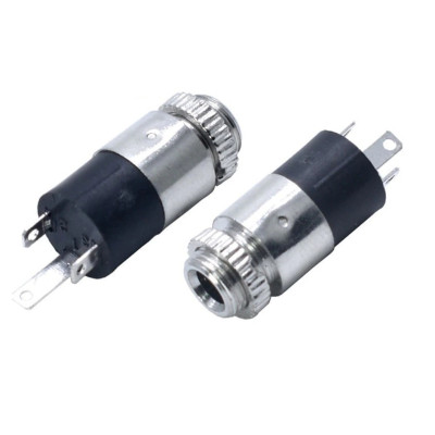
Female audio socket PJ392, threaded 3.5mm stereo jack, 3 contacts, panel mount
The threaded 3.5 mm female audio socket is ideal for building a reliable audio input in electronic projects and DIY equipment. The cylindrical connector is designed for panel mounting and is held firmly by the nut for vibration resistance. It provides a stable contact and easy insertion of the jack, compatible with common cables and enclosures, suitable for repairs and prototypes.
Shipping by Wednesday 11 November
Buying this product earns you Ft9.60 in loyalty points.

International fast shipping within EU. Free Shipping for orders above 100 EUR in most EU countries.

We ship from our stock within 24H

You earn points with every order, worth 5%.
The PJ392 female audio socket is a 3.5 mm stereo jack connector with a cylindrical metal body, external thread and knurled nut, designed for panel mounting. It is used as an audio input or output on project enclosures, amplifiers, active speakers, radio receivers and other audio equipment built or modified by the user, wherever a cable with a 3.5 mm jack plug from a phone, computer or player needs to be connected.
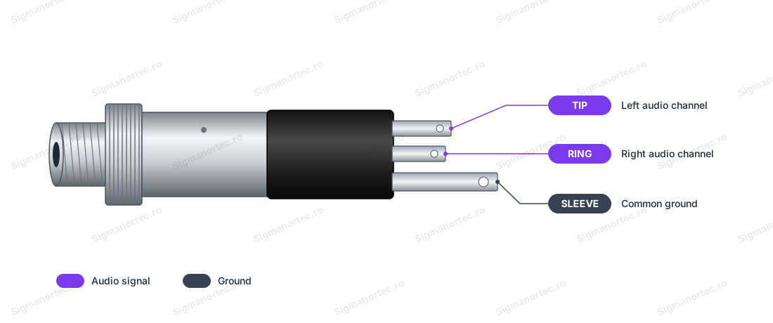
The socket has 3 contacts that match the three zones of a stereo plug: the tip (TIP) for the left channel, the middle ring (RING) for the right channel and the plug body (SLEEVE) for the common ground. It is a closed-type socket with no switching contacts, and the signal from the plug reaches the three solder tabs directly.
The main features include the threaded metal body, the knurled nut for panel fixing, the black insulating body at the rear and the solder tabs fitted with holes, in which the wire can be wound for a solid mechanical connection.
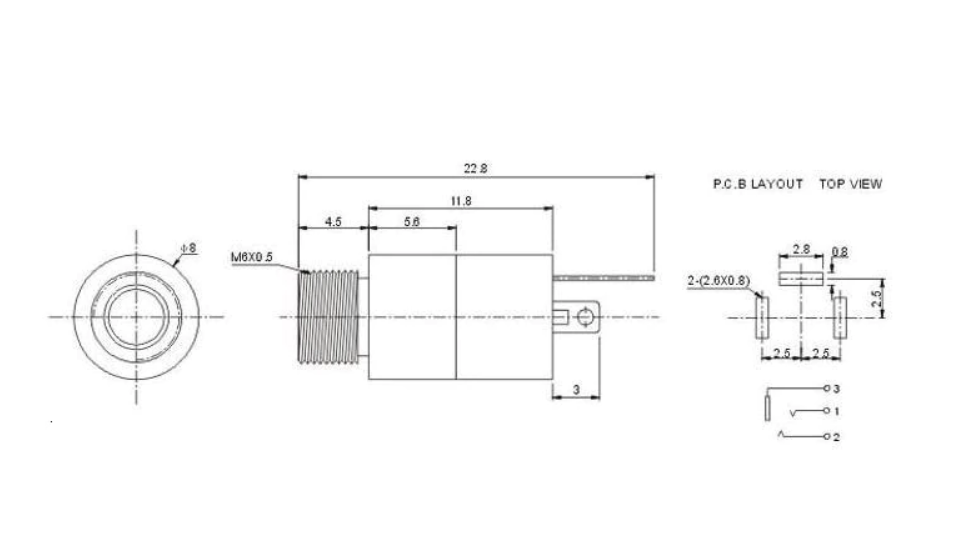
Specifications:
Rated voltage: 30 VDC
Rated current: 0.5 A
Type: Female audio socket, 3.5 mm, stereo
Number of contacts: 3 (TIP, RING, SLEEVE)
Socket type: Closed, no switching contacts
Mounting: Panel mount, with thread and knurled nut
Connection: Soldering to tabs
Contact resistance: maximum 0.03 ohms
Insulation resistance: minimum 100 Mohms
Withstand voltage: 500 VAC / minute
Operating temperature: -40 - 55 C
Service life: 5000 mating cycles
Layout:
| Element | Function |
|---|---|
| Jack plug opening | Receives the 3.5 mm stereo jack plug. |
| Knurled nut | Fixes the socket in the panel, tightened from the outside of the panel. |
| Threaded metal body | Passes through the hole in the panel and supports the nut. |
| Black insulating body | Supports and insulates the three contact tabs from each other. |
| TIP tab | Contacts the tip of the plug, left channel. Has the hole for winding the wire. |
| RING tab | Contacts the middle ring of the plug, right channel. Has the hole for winding the wire. |
| SLEEVE tab | Contacts the body of the plug, common ground. Has the hole for winding the wire. |
Pinout:
| Connector | Pin | Function |
|---|---|---|
| PJ392 | TIP | Audio signal left channel (tip of the plug) |
| PJ392 | RING | Audio signal right channel (middle ring of the plug) |
| PJ392 | SLEEVE | Common ground (body of the plug) |
Usage:
Identify the contacts before soldering, because the socket body does not mark which tab is TIP, RING or SLEEVE.
Insert a 3.5 mm stereo jack plug into the socket and set the multimeter to continuity measurement. Place one probe on the tip of the plug and touch each tab in turn with the other probe. When the multimeter beeps, that tab is TIP.
Repeat with the middle ring of the plug to find RING, and with the body of the plug to find SLEEVE. As a rule the longest tab is SLEEVE, but confirm with the multimeter on your part.
Solder the wires to the tabs before mounting the socket in the panel, because soldering on a socket that is already fixed is inconvenient. Wind the wire through the hole of the tab and insulate each tab with heat shrink tubing so that they do not touch each other.
Drill the panel with a bit of about 6.35 mm (1/4 inch). Insert the socket from the inside so that the thread comes through the panel, then tighten the knurled nut from the outside.
Use thin panels, about 2 mm, because the thread is short.
Connect TIP to the left channel input, RING to the right channel input and SLEEVE to the audio circuit ground.
Do not use the socket contacts for supply currents. The socket is made for audio signals, and its rated load is 30 VDC and 0.5 A.
For wires longer than 10 - 15 cm between the socket and the circuit, use shielded cable or twisted wires to reduce mains noise.
Insert the plug fully into the socket, because a plug inserted halfway can leave a channel without signal or short the contacts together.
- Type
- Female audio jack, 3.5 mm, stereo
- Operating temperature
- -40-55 °C
- Number of pins
- 3 (TIP, RING, SLEEVE)
- Rated voltage
- 30 V DC
- Mounting
- Panel mount, with thread and knurled nut
- Rated current
- 0.5 A
- Diameter
- 3.5 mm
- Service life
- 5000 mating cycles
- Contact resistance
- maximum 0.03 Ω
- Insulation resistance
- minimum 100 MΩ
Produs destinat utilizarii in proiecte electronice, automatizari, prototipare, educatie si cercetare.
Produsul trebuie utilizat numai conform specificatiilor tehnice mentionate in descriere si/sau in documentatia produsului.
Avertismente generale de siguranta:
Nu utilizati produsul la tensiuni, curenti sau temperaturi peste valorile specificate.
Montajul si conectarea trebuie realizate de persoane cu cunostinte tehnice minime in domeniul electric/electronic.
Evitati scurtcircuitele, inversarea polaritatii si conectarea gresita a alimentarii.
Nu lasati produsul alimentat nesupravegheat in timpul testelor.
Produsul nu este jucarie si nu este destinat copiilor.
Pentru modulele electronice, se recomanda utilizarea in carcase, panouri sau montaje protejate, dupa caz.
Identificare produs:
Denumirea produsului, codul/SKU-ul si caracteristicile tehnice sunt mentionate in pagina produsului si/sau pe eticheta ambalajului.
Producator / Importator / Distribuitor:
Sigmanortec S.R.L.
Calea Bucuresti nr. 9, Targu Jiu, Gorj, Romania
E-mail: [email protected]
Website: www.sigmanortec.ro
Persoana responsabila in UE:
Sigmanortec S.R.L.
Calea Bucuresti nr. 9, Targu Jiu, Gorj, Romania
E-mail: [email protected]
Documentatie si siguranta:
Pentru informatii suplimentare, fise tehnice, declaratii de conformitate sau instructiuni, ne puteti contacta la [email protected].
Reviews (4) - Review moderation

Mufa intra greu jar piulita daca vrei sa o strangi sare filetul
Mufa tata intra mai greu, dar nu e tocmai un neajuns.
OK Totul
Foarte multumit, recomand aceasta firma.
The PJ392 is a 3.5 mm stereo female audio jack with a cylindrical metal body, external thread and serrated nut, made for panel mounting. It is used as an audio input for project boxes, amplifiers, active speakers and home-built radios, where a jack cable from a phone, computer or player is plugged in.
It is a passive component, with no controller and no program. In this tutorial we mount it as a stereo input for a PAM8403 2 x 3 W amplifier module, powered from a 5 V mains adapter.

How it works:
The jack has 3 contacts that match the three zones of a 3.5 mm stereo plug. The tip (TIP) carries the left channel, the middle ring (RING) carries the right channel, and the body of the plug (SLEEVE) is the common ground. The jack is a closed type, so it has no switching contacts. It only brings the signal from the plug out to the three solder tabs.
The audio signal from a phone or a computer has a low voltage, around one volt, and a negligible current. For this reason the jack does not limit anything in the circuit, and the PAM8403 amplifier raises it to the level needed for the speakers. The PAM8403 module has bridge outputs (BTL), so each channel has two active terminals (+ and -) and neither of them is ground.
For the power supply we do a simple calculation. A 4 ohm speaker that receives 3 W needs an RMS current of the square root of (3 W / 4 ohms), that is about 0.87 A. For two channels at maximum power this gives, with a safety margin, a current of around 1.5 - 2 A, which is why we use a 5 V adapter with at least 2 A.
Connection:
Unplug the adapter from the wall socket before any soldering or change to the wiring. Power the PAM8403 module only at 5 V, because a higher voltage destroys it. The audio signal is analog, so there are no logic levels and no need for a level converter or pull-up resistors. The jack contacts carry only the audio signal and do not carry the amplifier supply current.
| Product pin | Connects to | Role |
|---|---|---|
| PJ392 jack, TIP contact | L input of the PAM8403 module | Left channel audio signal |
| PJ392 jack, RING contact | R input of the PAM8403 module | Right channel audio signal |
| PJ392 jack, SLEEVE contact | Ground pad at the audio input of the PAM8403 module | Audio signal ground |
| DC adapter with terminals, + terminal | 5V + terminal of the PAM8403 module | 5 V power supply |
| DC adapter with terminals, - terminal | 5V - terminal of the PAM8403 module | Power supply ground |
| PAM8403 module, L+ and L- | Left speaker 4 ohm 3 W, + terminal and - terminal | Left channel output |
| PAM8403 module, R+ and R- | Right speaker 4 ohm 3 W, + terminal and - terminal | Right channel output |
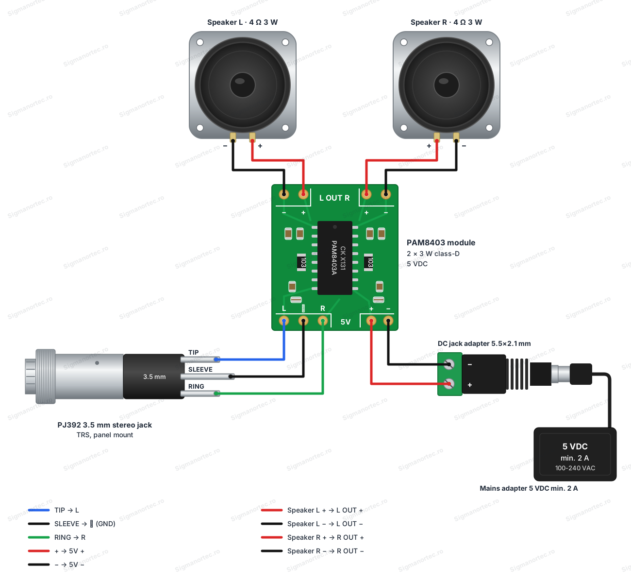
Never connect the L- or R- terminals to ground or to each other. Do not put two speakers in parallel on the same channel. Use speakers of 4 ohms or 8 ohms, with a power of at least 3 W.
Configuration:
The jack has no buttons, potentiometers, jumpers or LEDs, so there is nothing to adjust on it. The only preparation is identifying the contacts and mounting it in the panel. The body of the jack does not mark which tab is TIP, RING or SLEEVE, so we check them before soldering.
Step 1. Insert into the jack a 3.5 mm stereo plug, preferably one with a metal body or with accessible contacts.
Step 2. Set the multimeter to continuity mode. Place one probe on the tip of the plug and touch with the other probe, one by one, each tab of the jack. When the multimeter beeps, that tab is TIP.
Step 3. Repeat with the middle ring of the plug to find RING, and with the body of the plug, the part closest to the cable, to find SLEEVE. As a rule the longest tab is SLEEVE, but confirm it with the multimeter on your own part.
| Contact | Zone of the jack plug | Connects to |
|---|---|---|
| TIP | Tip of the plug | L input of the amplifier |
| RING | Middle ring | R input of the amplifier |
| SLEEVE | Body of the plug | Ground at the audio input |
Step 4. Solder the wires to the tabs before mounting in the panel, because soldering on a jack that is already fixed is inconvenient. The tabs have holes in which the wire can be wrapped for a solid mechanical connection. Insulate each tab with heat-shrink tubing, so that they do not touch each other.
Step 5. Drill the panel with a drill bit of about 6.35 mm (1/4 inch). Insert the jack from the inside, so that the thread comes out through the panel, then tighten the serrated nut from the outside. The thread is short, so the mounting suits thin panels, of about 2 mm.
Usage example:
We build an audio input for a small stereo speaker. Solder the wires to the PJ392 jack and mount it in the box panel, then connect TIP to the L input, RING to the R input and SLEEVE to the ground at the audio input of the PAM8403 module, as in the diagram. For wires longer than 10 - 15 cm use shielded cable or twisted wires, to reduce mains noise.
Connect the 4 ohm 3 W speakers to the L+ and L- terminals for the left channel and to R+ and R- for the right channel. Connect the DC adapter terminals to the 5V + and - terminals of the module, respecting the polarity. Check once more that no output terminal touches ground.
Reduce the volume on the phone or the computer to about half. Insert the jack cable fully into the PJ392 jack and only then connect the 5 V adapter to the wall socket. Increase the volume gradually. You should hear the sound in both speakers. To check the channel order, play a left - right test track. The sound must pass from one speaker to the other, in the correct order.
Common problems:
Nothing is heard. The usual cause is a missing power supply or an unsoldered SLEEVE contact. Measure 5 V between the power terminals of the module, check that the plug is inserted completely and that the ground of the jack reaches the ground at the audio input.
Only one channel is heard. One of the TIP or RING contacts is not soldered well or was connected wrongly. Repeat the check with the multimeter and redo the cold solder joint. If the sound comes out on the reversed channel, swap the wires between TIP and RING.
Noise or hum is heard. The wires between the jack and the module are too long or pass close to the mains cable. Shorten the wires, use shielded cable or twisted wires and check that the ground of the jack is connected to the ground at the audio input.
The sound is weak or distorted. The volume of the source is too low or too high, and the power supply may be insufficient. Adjust the volume of the source and use a 5 V adapter with at least 2 A.
The jack does not fit in the panel. The panel is too thick for the short thread of the jack or the hole is too small. Use a panel of about 2 mm and a hole of about 6.35 mm.
Limitations and tips:
The PJ392 jack is a connector for low-level audio signals. Its rated load is 30 VDC and 0.5 A, so do not use it for power supply or for high currents. Being a closed type, it does not automatically switch the audio source and does not turn off the speaker when the plug is inserted.
The short thread limits the mounting to thin panels, and the unmarked tabs must be checked with the multimeter before soldering.
With the same jack you can further build audio inputs for other amplifiers, simple mixers or project boxes. For tidier projects, use several jacks of the same type, each with a pair of labelled wires.