
Product images are for informational purposes only and may vary slightly depending on the batch and supplier. Product specifications and prices may be subject to change without notice. We do our best to provide accurate and complete product specifications, but they may not be completely accurate. If you encounter any such situation, please let us know.
The product is intended for specialists and requires qualified and authorized personnel. The product does not include assembly/use instructions . Putting the product into operation by unqualified persons leads to the loss of the warranty according to the Terms and Conditions on the site.
The specified technical parameters (current, power, etc.) represent maximum allowable values under ideal operating conditions. For safe use and optimal lifespan, it is recommended to operate the product continuously at no more than 50% of the specified maximum values.
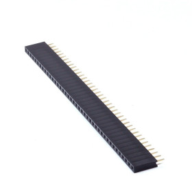
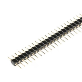
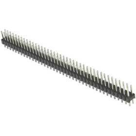
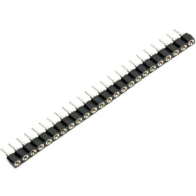
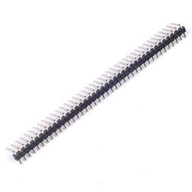
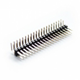
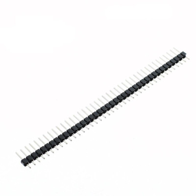
40-pin male header bar, single row, 2.54 mm pitch
40-pin male connector with 2.54 pitch, ideal for quick connections on PCBs, sensors and modules. Offers precise alignment and stable contact, the pins easily fit into header or breadboard, can be cut to the desired size for DIY and prototyping projects, reliable construction for repeated use.
Buying this product earns you 0.10 RON in loyalty points.

International fast shipping within EU. Free Shipping for orders above 100 EUR in most EU countries.

We ship from our stock within 24H

You earn points with every order, worth 5%.
The 40-pin male connector bar, in a single row with 2.54 mm pitch, is a straight pin header intended for soldering into PCBs and perfboards. It is used to equip modules, sensors and custom-made circuits with an output for connection, which can be inserted into a breadboard, female sockets or wires with dupont connectors.
The bar has 40 metal pins placed at a distance of 2.54 mm (0.1 inch) from each other, mounted in a black plastic body. The 2.54 mm distance is the one used on breadboards, perfboards and most electronic modules, and the total length of the full bar is 101.6 mm. The bar can be cut to the required length, and each piece remains a complete bar, with the pins aligned.
The main features include the black plastic body that keeps the pins aligned and insulates them from each other, straight pins with a short end for soldering and a long end for connection, and the option to cut it to any number of pins. It is a passive component, without power supply, and the maximum current and voltage depend on the assembly in which it is soldered.
Specifications:
Connector type: Male pin header, straight
Number of pins: 40
Number of rows: 1
Pin pitch: 2.54 mm (0.1 inch)
Body colour: Black
Mounting type: Through-hole soldering (THT)
Cutting: Can be cut to the desired length
Length: 101.6 mm
Layout:
| Element | Function |
|---|---|
| Short end of the pin | Goes into the hole of the PCB and is soldered, fixing the bar and making the electrical contact with the track. |
| Long end of the pin | Remains free above the plastic body and is inserted into the breadboard, into the female socket or into the wire with dupont connector. |
| Black plastic body | Keeps the pins aligned at 2.54 mm and electrically insulates them from each other. |
Usage:
Determine how many pins are needed and count them on the bar, keeping in mind that a free metal pin must remain at the place of the cut.
Remove the pin at the cutting point with small pliers, then cut the plastic body through the free space with cutting pliers or a cutter, so that the plastic does not break.
Insert the short ends of the pins into the holes of the board, from the side on which you want the plastic body to remain.
If the module must sit on a breadboard, first insert the long ends into the breadboard and place the module above, so that the pins remain straight.
Solder first one pin at one end and check that the bar sits perpendicular to the board, then solder the pin at the other end and after that the remaining pins.
Heat the pin and the pad simultaneously for 2 - 3 seconds, bring the solder wire in and withdraw it, then remove the soldering iron. A correct solder joint is shiny and has the shape of a small cone.
Check with a multimeter in continuity mode that each pin has contact with its pad and that two neighbouring pins are not short-circuited.
Check the position of the module before powering it, because the bar has no polarization and does not protect against reverse connection.
Do not overheat the plastic body, because it can deform, and the pins lose their alignment.
- Colour
- Black
- Number of pins
- 40
- Length
- 101.6 mm
- Connector type
- Male pin header, straight
- Mounting
- THT
- Pin pitch
- 2.54 mm
Produs destinat utilizarii in proiecte electronice, automatizari, prototipare, educatie si cercetare.
Produsul trebuie utilizat numai conform specificatiilor tehnice mentionate in descriere si/sau in documentatia produsului.
Avertismente generale de siguranta:
Nu utilizati produsul la tensiuni, curenti sau temperaturi peste valorile specificate.
Montajul si conectarea trebuie realizate de persoane cu cunostinte tehnice minime in domeniul electric/electronic.
Evitati scurtcircuitele, inversarea polaritatii si conectarea gresita a alimentarii.
Nu lasati produsul alimentat nesupravegheat in timpul testelor.
Produsul nu este jucarie si nu este destinat copiilor.
Pentru modulele electronice, se recomanda utilizarea in carcase, panouri sau montaje protejate, dupa caz.
Identificare produs:
Denumirea produsului, codul/SKU-ul si caracteristicile tehnice sunt mentionate in pagina produsului si/sau pe eticheta ambalajului.
Producator / Importator / Distribuitor:
Sigmanortec S.R.L.
Calea Bucuresti nr. 9, Targu Jiu, Gorj, Romania
E-mail: [email protected]
Website: www.sigmanortec.ro
Persoana responsabila in UE:
Sigmanortec S.R.L.
Calea Bucuresti nr. 9, Targu Jiu, Gorj, Romania
E-mail: [email protected]
Documentatie si siguranta:
Pentru informatii suplimentare, fise tehnice, declaratii de conformitate sau instructiuni, ne puteti contacta la [email protected].
Reviews (21) - Review moderation

E OK! se poate taia usor (daca e nevoie).
FB
totul ok .recomand
calitate buna.
ok
A 40-pin male strip, with a 2.54 mm pitch, is a single-row pin header made for soldering onto PCBs. It is used to equip modules, sensors and custom circuits with an output on pins, which can be inserted into a breadboard or female sockets.
The tutorial explains step by step how to cut the strip to length, how to solder it and how to check the result. The strip is a passive component, with no power supply and no program, so the tutorial does not use any electronic board, only soldering tools.

How it works:
The strip has 40 metal pins mounted in a black plastic body, spaced 2.54 mm (0.1 inch) apart. This distance is the standard for breadboards, perforated boards and most modules, so the pins fit directly into their holes.
Each pin is a separate metal piece, with no electrical connection to its neighbours. One end of the pin goes into the board hole and is soldered, while the other end stays free for the breadboard, female socket or dupont wire. The plastic body only keeps the pins aligned and insulates them from each other.
The length of the full strip is 40 x 2.54 mm = 101.6 mm. For a piece with n pins, the distance between the first and last pin is (n - 1) x 2.54 mm. For example, a piece of 8 pins has 7 x 2.54 mm = 17.78 mm between its end pins, a value you can use to check whether the cut piece matches the board holes.
Connection:
The strip is not powered and has no logic level of its own, so there is no voltage to respect on it. The pins only carry the signal or power of the circuit they are soldered to, and the maximum current and voltage are those of the equipped module and of the connections used. The table shows the role of each part of the strip.
| Product pin | Connects to | Role |
|---|---|---|
| Short end of the pin | Hole in the PCB, by soldering | Fixes the strip and makes the electrical contact with the board track. |
| Long end of the pin | Breadboard, female socket or dupont wire | Carries the signal or power of the module to the rest of the assembly. |
| Black plastic body | PCB surface | Keeps the pins aligned at 2.54 mm and insulates them from each other. |
Configuration:
Determine how many pins you need and count them on the strip, adding one extra pin at the cutting point. The plastic breaks cleanly only through the space without a pin, so remove the pin at the cutting point with small pliers, so that a free space remains between the two pieces.
Cut the plastic through the free space with cutting pliers or a cutter. Then check that the last pin of each piece is firmly held in the plastic and that no sharp edges remain.
Insert the short ends of the pins into the module holes, from the side on which you want the plastic body to stay. If the module must sit on a breadboard, first insert the long ends into the breadboard and place the module on top, so that the pins stay straight.
Solder first a single pin at one end and check whether the strip sits perpendicular to the board. If it has tilted, reheat the joint and correct the position. Then solder the pin at the other end and, after that, the remaining pins.
Heat the pin and the pad together with the soldering iron tip for 2 - 3 seconds, then bring the solder. A correct joint has the shape of a small shiny cone that covers the pad and climbs up the pin. Withdraw the solder, then the iron, and do not move the board until the joint has cooled.
Usage example:
You have a module with 8 connection positions, supplied without pins, which you want to use on a breadboard. Count 9 pins on the strip and remove the ninth with pliers. Cut the plastic through the free space and you will obtain a piece of 8 pins.
Place the piece with the long ends down into the breadboard, then put the module over the short ends that stick out and solder the 8 pins, starting with the first and the last.
After cooling, check with a multimeter in continuity mode that each pin has contact with its pad and that two neighbouring pins are not short-circuited. The correct result is a beep for each pin measured against its pad and silence between neighbouring pins. Then remove the module from the breadboard, and it is ready to use.
Common problems:
The plastic cracks or crumbles when cutting. The cause is that the cut went through a pin or too close to it. Remove the pin at the cutting point and cut through the free space.
The strip does not fit into the board holes. The cause may be a bent pin or a hole clogged with solder. Straighten the pin with pliers and clear the hole with a desoldering pump.
Two neighbouring pins have contact with each other after soldering. The cause is too much solder or a soldering iron that is too hot. Add flux on the spot, reheat the joint and draw off the excess with desoldering braid.
The signal appears and disappears or the module does not make a secure contact. The cause is usually a cold, dull and grainy joint. Reheat the joint with a little fresh solder until it becomes shiny.
The strip has remained tilted on the board. The cause is soldering all the pins without first fixing the position. Desolder the joint at the ends, align the strip and solder one pin again, checking the position.
Limitations and tips:
The strip is a simple connector, with no polarisation, no reverse-polarity protection and no housing. Check carefully the position of the module on the breadboard or in the socket before applying power. For high currents use several pins in parallel or wires soldered directly, because each pin has a small cross-section.
Do not overheat the plastic body, as it may deform and the pins lose their alignment. When soldering several strips in a row, let the board cool between them.
From the same strip you can make connecting links for sensors, programming headers and adapters on perforated boards. After soldering, the piece fits into female sockets with a 2.54 mm pitch and into breadboards.