
Product images are for informational purposes only and may vary slightly depending on the batch and supplier. Product specifications and prices may be subject to change without notice. We do our best to provide accurate and complete product specifications, but they may not be completely accurate. If you encounter any such situation, please let us know.
The product is intended for specialists and requires qualified and authorized personnel. The product does not include assembly/use instructions . Putting the product into operation by unqualified persons leads to the loss of the warranty according to the Terms and Conditions on the site.
The specified technical parameters (current, power, etc.) represent maximum allowable values under ideal operating conditions. For safe use and optimal lifespan, it is recommended to operate the product continuously at no more than 50% of the specified maximum values.
WiFi module for RD6006
Adds wireless control and monitoring for the RD6006 power supply, by connecting directly to the existing internal socket, without modifications. The module is exclusively compatible with the RD6006, uses the integrated ESP8266 for WiFi communication, allows quick access to settings and reading of parameters remotely, ideal for automation and integration into laboratory projects.
Shipping by Thursday 22 October
Buying this product earns you 0.89 € in loyalty points.

International fast shipping within EU. Free Shipping for orders above 100 EUR in most EU countries.

We ship from our stock within 24H

You earn points with every order, worth 5%.
The WiFi module for the RD6006 power supply is the communication board that mounts into the socket inside the power supply and adds wireless connectivity. The power supply can be controlled and monitored remotely from the manufacturer’s app, through the local WiFi network, without a USB cable. The module is suitable for a workbench, laboratory, battery charging, and any situation in which the power supply needs to be monitored or controlled remotely.
The board integrates the ESP-12F module with the ESP8266EX circuit, which operates on the 2.4 GHz WiFi network (802.11 b/g/n). The module does not work in the 5 GHz band. Communication with the power supply is done through the UART serial interface, on the TX and RX pins of the socket. The board includes a DC-DC converter that provides the 3.3 V required by the ESP-12F module from the 5 V supplied by the power supply.
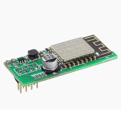
Among the main features are the ESP-12F module with printed antenna, the DC-DC converter for 3.3 V with its associated inductor, the electrolytic capacitor for filtering the 5 V supply voltage, the bias resistors for the EN, RST, GPIO0 and GPIO15 pins, and the 2.54 mm pitch connection pins. The module has no separate power supply, since it receives 5 V directly from the power supply socket.
The module is intended exclusively for the RD6006 power supply, whose communication module socket is already present inside, and it is installed without any modification.
Specifications:
Power supply voltage: 5 VDC (provided by the power supply through the communication socket)
WiFi module: ESP-12F
Integrated circuit: ESP8266EX
WiFi standard: 802.11 b/g/n, 2.4 GHz
Interface with power supply: UART (TX / RX)
Internal logic voltage: 3.3 V, generated on the board by a DC-DC converter
Antenna: Printed on the ESP-12F module
Pin pitch: 2.54 mm
Compatibility: Exclusively with the RD6006 power supply
Layout:
| Element | Function |
|---|---|
| ESP-12F module (U2) | WiFi module with the ESP8266EX circuit, responsible for network connection and serial communication with the power supply. |
| Printed antenna | 2.4 GHz antenna of the ESP-12F module, which must not be covered. |
| DC-DC converter (U1) and inductor | Generate the 3.3 V voltage for the ESP-12F module from the 5 V voltage of the power supply. |
| Electrolytic capacitor (C20) | Filters the 5 V supply voltage. |
| SMD ceramic capacitors | Filter the 5 V and 3.3 V voltages. |
| Resistors R4 - R7 | Bias the EN, RST, GPIO0 and GPIO15 pins of the ESP-12F module. |
| Connection pins | Electrical connection with the communication socket inside the RD6006 power supply. |
Pinout:
| Connector | Pin | Function |
|---|---|---|
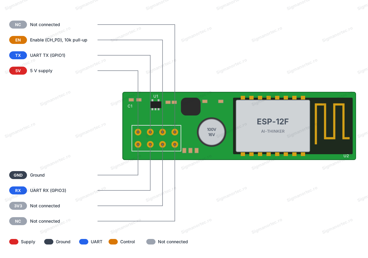
| Power supply socket pins | 5V | 5 VDC power received from the power supply |
| Power supply socket pins | GND | Ground |
| Power supply socket pins | TX | UART data transmission of the ESP-12F module (GPIO1 / TXD) |
| Power supply socket pins | RX | UART data reception of the ESP-12F module (GPIO3 / RXD) |
| Power supply socket pins | EN | Module enable, connected to the EN (CH_PD) pin of the ESP-12F, with a 10 k pull-up resistor |
| Power supply socket pins | 3V3 | Not connected on the module |
| Power supply socket pins | NC | Not connected |
Usage:
Turn off and completely disconnect the RD6006 power supply from mains power before opening the case, because dangerous voltages are present inside.
Insert the module into the communication socket inside the power supply, with the pins correctly aligned and without forcing.
Do not cover the printed antenna area with metal parts or cables, for a stable WiFi connection.
Close the case and power on the supply.
Set the communication interface to WiFi in the power supply menu, then restart the power supply.
Place the power supply and the phone near the 2.4 GHz router and connect the phone to the same 2.4 GHz network, then follow the setup steps in the manufacturer’s app.
Do not use a 5 GHz network, because the module only works in the 2.4 GHz band.
Do not power the module through the 3V3 pin, which is not connected, but only through the 5V and GND pins.
For alternative firmware, remove the module from the power supply, power it at 5 V, connect a USB-TTL adapter to the GND, TX and RX pins, and hold GPIO0 at ground during startup.
When using alternative firmware, reconfigure the power supply communication interface according to the instructions of the chosen firmware.
Produs destinat utilizarii in proiecte electronice, automatizari, prototipare, educatie si cercetare.
Produsul trebuie utilizat numai conform specificatiilor tehnice mentionate in descriere si/sau in documentatia produsului.
Avertismente generale de siguranta:
Nu utilizati produsul la tensiuni, curenti sau temperaturi peste valorile specificate.
Montajul si conectarea trebuie realizate de persoane cu cunostinte tehnice minime in domeniul electric/electronic.
Evitati scurtcircuitele, inversarea polaritatii si conectarea gresita a alimentarii.
Nu lasati produsul alimentat nesupravegheat in timpul testelor.
Produsul nu este jucarie si nu este destinat copiilor.
Pentru modulele electronice, se recomanda utilizarea in carcase, panouri sau montaje protejate, dupa caz.
Identificare produs:
Denumirea produsului, codul/SKU-ul si caracteristicile tehnice sunt mentionate in pagina produsului si/sau pe eticheta ambalajului.
Producator / Importator / Distribuitor:
Sigmanortec S.R.L.
Calea Bucuresti nr. 9, Targu Jiu, Gorj, Romania
E-mail: [email protected]
Website: www.sigmanortec.ro
Persoana responsabila in UE:
Sigmanortec S.R.L.
Calea Bucuresti nr. 9, Targu Jiu, Gorj, Romania
E-mail: [email protected]
Documentatie si siguranta:
Pentru informatii suplimentare, fise tehnice, declaratii de conformitate sau instructiuni, ne puteti contacta la [email protected].