
Product images are for informational purposes only and may vary slightly depending on the batch and supplier. Product specifications and prices may be subject to change without notice. We do our best to provide accurate and complete product specifications, but they may not be completely accurate. If you encounter any such situation, please let us know.
The product is intended for specialists and requires qualified and authorized personnel. The product does not include assembly/use instructions . Putting the product into operation by unqualified persons leads to the loss of the warranty according to the Terms and Conditions on the site.
The specified technical parameters (current, power, etc.) represent maximum allowable values under ideal operating conditions. For safe use and optimal lifespan, it is recommended to operate the product continuously at no more than 50% of the specified maximum values.
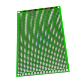
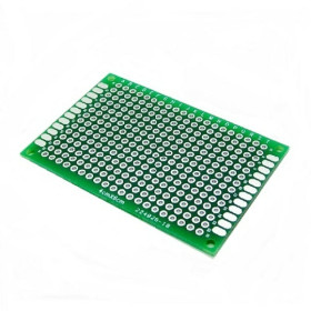
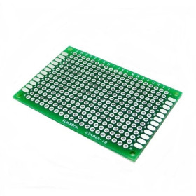
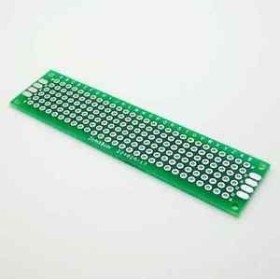
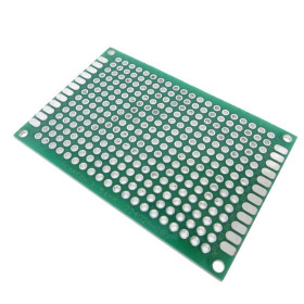
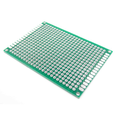
Single-sided prototyping PCB, 7x9 cm, FR4, 2.54 mm pitch
Ideal for quickly building prototype circuits and testing components, this single-sided prototyping board offers a stable base that is easy to work with. Its compact 7 x 9 cm size and standard FR4 construction provide rigidity and good insulation, allowing precise soldering and easy integration into small or medium electronic projects.
Buying this product earns you 0.32 RON in loyalty points.

International fast shipping within EU. Free Shipping for orders above 100 EUR in most EU countries.

We ship from our stock within 24H

You earn points with every order, worth 5%.
The single-sided prototyping PCB, measuring 7 x 9 cm, is a universal support for soldering through-hole components and building one-off electronic circuits. It is used for final assemblies based on a circuit tested first on a breadboard, for adapters, small power supplies, sensor interfaces, test wiring and soldering exercises.
The board is made of FR4, a laminate of glass fibre and epoxy resin, which is rigid and resistant to soldering heat. It has a regular grid of holes spaced 2.54 mm (0.1 inch) apart, the same as the spacing between the legs of most through-hole components, pin headers and IC sockets. Each hole has its own metal solder ring and is not connected to the neighbouring holes, so connections are made freely, using solder bridges, bent component legs or thin wires.
The main features include the 2.54 mm hole grid, the individual solder rings, the elongated contact areas on the short edges of the board, useful for bringing connections out to the edge, the letter markings on the edge for orientation, and four large holes in the corners for mounting on standoffs or in an enclosure. The board is not powered and has no signals of its own, it withstands the voltage at which the components mounted on it operate.
Specifications:
Type: Single-sided prototyping board
Material: FR4
Hole spacing: 2.54 mm (0.1 inch)
Mounting holes: 4, in the corners
Dimensions: 70 x 90 mm
Layout:
| Element | Function |
|---|---|
| Holes with metal ring | Hole grid at 2.54 mm for the legs of through-hole components, pin headers and IC sockets. Each hole is an isolated solder point, not connected to the neighbouring holes. |
| Elongated contact areas | Access points placed at the edge of the board, on the short sides, for soldering power or signal wires to the outside. |
| Large corner holes | Four holes for screws and standoffs, used only for mechanical fixing. They are not used for electrical connections. |
| Letter markings on the edge | The letters silkscreened on the edge help locate and count the rows of holes when planning the placement of components. |
Usage:
Plan the placement of components on paper before soldering, with the position of the integrated circuits, connectors and power wires.
Insert the through-hole components from the side without solder rings, then turn the board over and gently bend the legs so the parts do not fall out during soldering.
Heat the metal ring and the leg together for 1 - 2 seconds, then add solder until it forms a small, shiny cone. Use a temperature of about 320 - 350 degrees Celsius for leaded solder.
Make connections between points with a solder bridge between two neighbouring rings, with a bent component leg or with thin wires soldered between points.
Cut the remaining legs close to the solder joint, then check that there are no unwanted bridges between neighbouring rings.
Observe the polarity and the maximum voltage of the mounted components. For high currents use thicker wires or reinforce the trace with solder, and for high voltages keep safe distances between solder points.
Do not use the board for mains voltage of 220 VAC without proper insulation.
Fix the board with screws and standoffs through the corner holes.
- Dimensions
- 70 x 90 mm
- Material
- FR4
- Type
- Single-sided prototyping board
- Pin pitch
- 2.54 mm
Produs destinat utilizarii in proiecte electronice, automatizari, prototipare, educatie si cercetare.
Produsul trebuie utilizat numai conform specificatiilor tehnice mentionate in descriere si/sau in documentatia produsului.
Avertismente generale de siguranta:
Nu utilizati produsul la tensiuni, curenti sau temperaturi peste valorile specificate.
Montajul si conectarea trebuie realizate de persoane cu cunostinte tehnice minime in domeniul electric/electronic.
Evitati scurtcircuitele, inversarea polaritatii si conectarea gresita a alimentarii.
Nu lasati produsul alimentat nesupravegheat in timpul testelor.
Produsul nu este jucarie si nu este destinat copiilor.
Pentru modulele electronice, se recomanda utilizarea in carcase, panouri sau montaje protejate, dupa caz.
Identificare produs:
Denumirea produsului, codul/SKU-ul si caracteristicile tehnice sunt mentionate in pagina produsului si/sau pe eticheta ambalajului.
Producator / Importator / Distribuitor:
Sigmanortec S.R.L.
Calea Bucuresti nr. 9, Targu Jiu, Gorj, Romania
E-mail: [email protected]
Website: www.sigmanortec.ro
Persoana responsabila in UE:
Sigmanortec S.R.L.
Calea Bucuresti nr. 9, Targu Jiu, Gorj, Romania
E-mail: [email protected]
Documentatie si siguranta:
Pentru informatii suplimentare, fise tehnice, declaratii de conformitate sau instructiuni, ne puteti contacta la [email protected].
Reviews (5) - Review moderation

:)
Bun!
Ok
Ok
Recomand , suport din fibra
This tutorial uses the prototyping board itself, with components and wires soldered onto it. No development board and no program are needed. The 7 x 9 cm single-sided board is used for permanent builds made after a circuit has first been tested on a breadboard, for adapters, small power supplies, sensor interfaces or soldering practice.
The board is made of FR4, a laminate of fiberglass and epoxy resin, which is rigid and resistant to soldering heat. If you are working with this type of board for the first time, follow the steps below in order.

How it works:
The board has a regular grid of holes spaced 2.54 mm apart (0.1 inch). This spacing is the same as the spacing of the legs of most through-hole components, pin headers and IC sockets. For example, a DIP integrated circuit has two rows of pins at 7.62 mm, which is exactly 3 hole steps.
Each hole has a metal ring around it where the solder is applied. The holes are not connected to each other, so the board does not have ready-made tracks. You make the connections yourself, with a drop of solder bridging two neighboring rings, with a bent component leg or with thin wires soldered between points.
The board dimensions are 7 x 9 cm, that is 70 x 90 mm. On two sides there are elongated contact zones placed at the edge of the board, and in the corners there are four larger holes for fixing it in an enclosure or on standoffs. Along the edges the rows of holes are marked with letters, which helps with orientation.
For a series resistor with an LED, the formula R = (Vsupply - Vled) / I is used. With a 5 V supply, a red LED with a forward voltage of about 2 V and a desired current of 10 mA, we get R = (5 - 2) / 0.01 = 300 ohms. The nearest standard value is 330 ohms, which gives a current of about 9 mA.
The values of 2 V and 10 mA are indicative and depend on the LED used. Check the LED datasheet before calculating.
Connection:
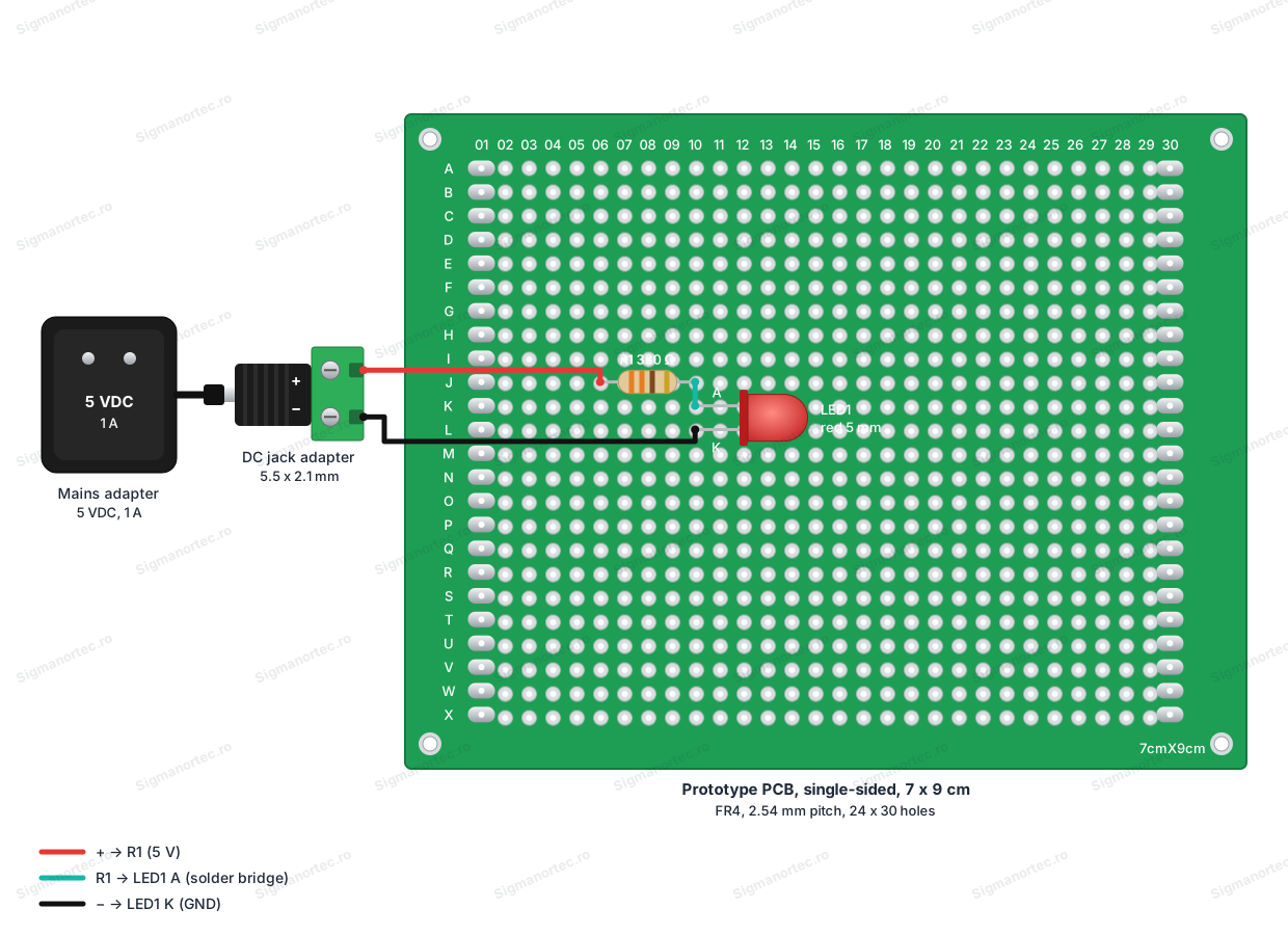
The board does not get powered and has no signals of its own. The example in this tutorial solders onto the board a 330 ohm resistor and a 5 mm red LED, powered from a 5 VDC mains adapter with a 5.5 x 2.1 mm DC barrel jack adapter with screw terminals (marked + and -). A 1 A adapter is sufficient, because the circuit consumes about 9 mA. Use a certified mains adapter and do not open it. The circuit on the board works only at 5 V.
| Product pin | Connects to | Role |
|---|---|---|
| Hole J06 (first leg of resistor R1 of 330 ohms) | The + terminal of the DC barrel jack adapter, through a wire | Brings the +5 V to the resistor. |
| Hole J10 (second leg of resistor R1) | Hole K10, through a solder bridge | Connects the resistor to the LED anode. |
| Hole K10 (LED anode, the longer leg) | Hole J10, through a solder bridge | Receives the current limited by the resistor. |
| Hole L10 (LED cathode, the shorter leg) | The - terminal of the DC barrel jack adapter, through a wire | Ground (GND) of the assembly. |
| The four large holes in the corners | Screws and standoffs | Mechanical fixing of the board. They are not used for electrical connections. |
You bring the power supply into the assembly yourself, from the source chosen for your circuit. The board supports any voltage level that the components mounted on it can tolerate. Respect the polarity and the maximum voltage of the components.
Configuration:
The board has no buttons, potentiometers, jumpers or LEDs of its own, so there are no adjustments to make on it. Preparation consists of planning the layout and choosing the soldering parameters.
| Parameter | Recommended value | Reason |
|---|---|---|
| Soldering iron temperature | 320 - 350 degrees Celsius for leaded solder | A temperature that is too high or heating for too long can detach the metal ring from the board. |
| Heating time | 1 - 2 seconds on the ring and leg together | The solder flows evenly over the ring and the leg, and the joint comes out shiny. |
| Joint shape | Small, shiny cone | A dull joint, or solder only on the leg, is cold and does not make good contact. |
| Component pitch | 2.54 mm | SMD components are mounted on adapters with pins at 2.54 mm. |
Draw on paper the placement of the integrated circuits, connectors and power wires before soldering. Use the letter markings on the edge to find the rows easily. For a tidy assembly, group the circuits in separate zones and make the common ground with a thick wire.
Usage example:
The example assembles an LED with a limiting resistor, powered at 5 V. You need a soldering iron, solder, a cutting pliers, a 5 mm red LED, a 330 ohm resistor (orange, orange, brown, gold bands), two wires and the 5 VDC adapter with DC barrel jack adapter.
Insert resistor R1 into holes J06 and J10, with one leg in each hole. Then insert the LED so that the anode, the longer leg, is in hole K10, next to J10, and the cathode, the shorter leg, is in L10.
Turn the board over to the side with the metal rings and bend the legs slightly, so the components do not fall out while you solder. Heat the ring and the leg together for 1 - 2 seconds, then add solder until it forms a small, shiny cone. Do not add too much solder.
Make a small solder bridge between rings J10 and K10, to connect the resistor to the LED anode. Check that the bridge does not touch ring L10.
Solder a wire between ring J06 and the + terminal of the DC barrel jack adapter. Solder another wire between ring L10 and the - terminal of the adapter. Cut the remaining leg ends close to the joint.
Connect the 5 VDC adapter to the mains. The LED should light up with constant brightness. If it does not light, disconnect the adapter and check the LED polarity and the joints. The current through the LED is about 9 mA.
Common problems:
The component does not make contact. The cause is usually a cold or dull joint, or solder that stayed on the leg and not on the ring. Reheat the joint and add a little fresh solder.
Two neighboring points are joined unintentionally. Excess solder has formed a bridge between rings. Heat the bridge and remove the excess with copper solder wick or with a solder sucker.
The metal ring detaches from the board. The soldering iron was held on too long or at too high a temperature. Work with a moderate temperature, around 320 - 350 degrees Celsius for leaded solder, and solder briefly.
The component does not fit into the hole. The leg is too thick for the 2.54 mm hole. Choose another hole or slightly thin the leg, without deforming it.
The assembly works on the breadboard, but not on the board. Check whether you copied all the connections, including the ground ones. On the prototyping board the holes are not connected to each other as on a breadboard.
Limitations and tips:
The board has no ready-made tracks, so every connection is made by hand. For large circuits, plan the placement on paper before soldering.
The 2.54 mm spacing limits the board to through-hole components or modules with pins at the same pitch. SMD components are mounted on adapters with pins at 2.54 mm.
For high currents use thicker wires or fill the path with solder, to increase the cross-section. For high voltages keep safe distances between the solder points. Do not use the board for 220 VAC mains voltage without proper insulation.
Grouping the circuits in separate zones, with a common ground made with a thick wire, helps a tidy assembly. You can then mount the board in an enclosure using the four holes in the corners.