

Product images are for informational purposes only and may vary slightly depending on the batch and supplier. Product specifications and prices may be subject to change without notice. We do our best to provide accurate and complete product specifications, but they may not be completely accurate. If you encounter any such situation, please let us know.
The product is intended for specialists and requires qualified and authorized personnel. The product does not include assembly/use instructions . Putting the product into operation by unqualified persons leads to the loss of the warranty according to the Terms and Conditions on the site.
The specified technical parameters (current, power, etc.) represent maximum allowable values under ideal operating conditions. For safe use and optimal lifespan, it is recommended to operate the product continuously at no more than 50% of the specified maximum values.
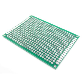
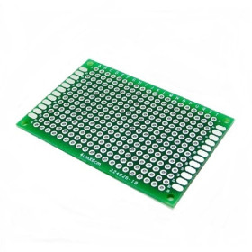
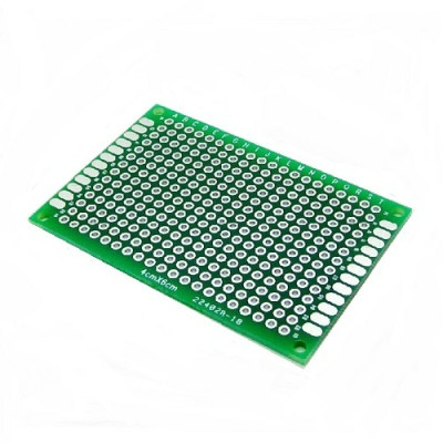
Prototyping PCB board, single-sided, 5x7 cm, FR4, 2.54 mm pitch
Ideal for quickly building prototypes and experimental circuits, this single-sided prototyping board provides a stable base for soldering and testing. It has compact dimensions of 5 x 7 cm, is made of standard FR4 for rigidity and thermal resistance, allows orderly arrangement of components and is perfect for laboratory or hobby electronics projects.
Buying this product earns you 0.15 RON in loyalty points.

International fast shipping within EU. Free Shipping for orders above 100 EUR in most EU countries.

We ship from our stock within 24H

You earn points with every order, worth 5%.
Single-sided prototyping board made of FR4, it is a support with holes for components with terminals, used to transfer a circuit from a breadboard to a soldered board. It is suitable for one-off circuits, adapters, small modules, power supply sections and laboratory tests.
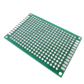
The board measures 50 x 70 mm and has pad holes at the standard 2.54 mm pitch, compatible with most through-hole components and pin headers. The holes are not connected to each other, so each pad is a separate point. Connections between components are made with solder, connecting wires or the component leads.
The main features include the single-sided pad hole grid, elongated edge pads for power and signal wires, and mounting holes in the corners. The board is passive, has no power supply of its own, and the limits of the assembly are set by the soldered components and the wires used for connections.
Specifications:
Type: Single-sided pad prototyping board
Material: FR4
Hole pitch: 2.54 mm
Dimensions: 50 x 70 mm
Layout:
| Element | Function |
|---|---|
| Pad holes | Receive the component terminals, which are soldered onto the pad on the copper side. Each pad is isolated from the others. |
| Edge pads | Used for power and signal wires that bring voltage and signals from outside the board. |
| Mounting holes | Corner holes for fixing the board with screws or standoffs. |
Usage:
Draw the schematic on paper before soldering and determine the position of each component and the route of each connection.
Mount the components on the side without copper, turn the board over and solder the terminals to the pads, 2 - 3 seconds for each joint.
Cut off the excess terminal with side cutters, leaving about 1 mm above the joint.
Make connections between neighbouring pads with a drop of solder, and for longer distances use short wires. Crossing connections are made with insulated wires.
Check that no solder bridge joins pads that should not be connected, preferably with a multimeter in continuity mode, before applying power.
Check the rated voltage and polarity of each component before soldering, and power the assembly only after the joints have cooled.
Do not use the board for 220 VAC mains voltages without proper insulation distances and without a protective enclosure.
After soldering, clean the flux residue with isopropyl alcohol and a soft brush. Do not force terminals that do not fit into the holes, as the pads may come off.
- Dimensions
- 50 x 70 mm
- Material
- FR4
- Type
- Single-sided prototyping board
- Pin pitch
- 2.54 mm
Produs destinat utilizarii in proiecte electronice, automatizari, prototipare, educatie si cercetare.
Produsul trebuie utilizat numai conform specificatiilor tehnice mentionate in descriere si/sau in documentatia produsului.
Avertismente generale de siguranta:
Nu utilizati produsul la tensiuni, curenti sau temperaturi peste valorile specificate.
Montajul si conectarea trebuie realizate de persoane cu cunostinte tehnice minime in domeniul electric/electronic.
Evitati scurtcircuitele, inversarea polaritatii si conectarea gresita a alimentarii.
Nu lasati produsul alimentat nesupravegheat in timpul testelor.
Produsul nu este jucarie si nu este destinat copiilor.
Pentru modulele electronice, se recomanda utilizarea in carcase, panouri sau montaje protejate, dupa caz.
Identificare produs:
Denumirea produsului, codul/SKU-ul si caracteristicile tehnice sunt mentionate in pagina produsului si/sau pe eticheta ambalajului.
Producator / Importator / Distribuitor:
Sigmanortec S.R.L.
Calea Bucuresti nr. 9, Targu Jiu, Gorj, Romania
E-mail: [email protected]
Website: www.sigmanortec.ro
Persoana responsabila in UE:
Sigmanortec S.R.L.
Calea Bucuresti nr. 9, Targu Jiu, Gorj, Romania
E-mail: [email protected]
Documentatie si siguranta:
Pentru informatii suplimentare, fise tehnice, declaratii de conformitate sau instructiuni, ne puteti contacta la [email protected].
Reviews (9) - Review moderation

Bun
Nu am apucat sa o folosesc inca, dar pare ok
Ok
OK Totul
Ok
Single-sided FR4 prototyping board, 5 x 7 cm, is a passive support with holes for components with terminals. It is used to move a circuit from a breadboard to a soldered board, for one-off circuits, adapters and laboratory tests. This tutorial does not use any development board or any program. We build a power indicator LED at 5 V on the board, with one resistor and one LED.

How it works:
The board has no electronics of its own. It is an insulating layer of FR4, that is glass fibre impregnated with epoxy resin, with a grid of holes at a 2.54 mm pitch. Components are mounted on one side, and their terminals are soldered to the pads on the other side. The solder makes both the mechanical and the electrical connection.
The holes are not connected to each other by default. You make the connections yourselves, with solder drops, connecting wires or the component terminals. That is why you draw the schematic on paper before soldering.
The board has no rated voltage or current of its own. The limits are set by the soldered components, the wires used and the spacing between pads. In our example the current through the LED results from Ohm's law: (5 V - 2.0 V) / 330 ohms, which is approximately 9 mA for a red LED whose forward voltage drop is around 1.8 - 2.2 V.
Connection:
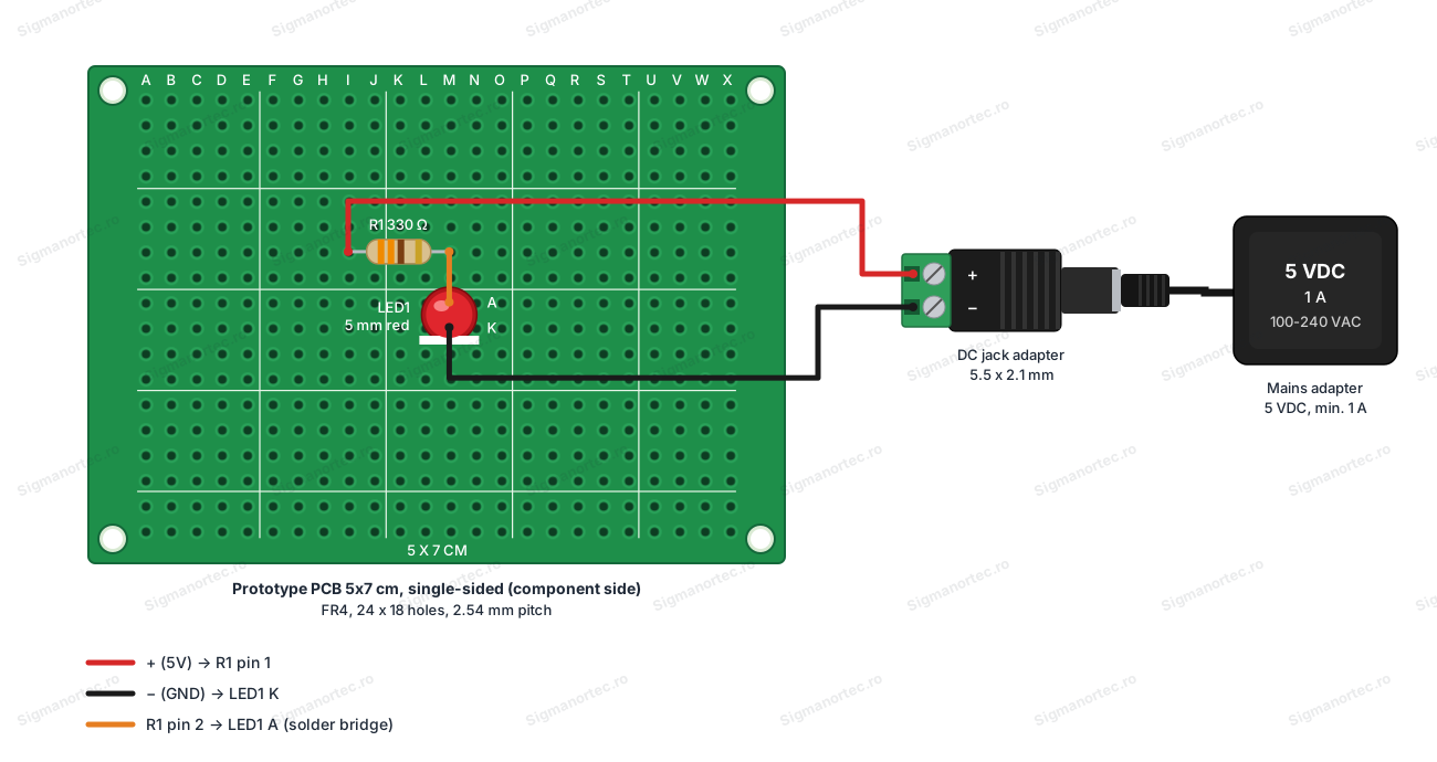
The board has no pins and is not powered directly. Power comes from a 5 VDC mains adapter, minimum 1 A, with a 5.5 x 2.1 mm DC barrel plug with screw terminals. The circuit draws only about 10 mA. Respect the polarity marked + and - on the barrel plug adapter. The circuit has only one LED and one resistor, so no other components are needed.
| Product pin | Connect to | Role |
|---|---|---|
| Pad for R1 pin 1 | The + terminal of the DC barrel plug adapter (red wire) | Brings the 5 V supply to the resistor |
| Pad for R1 pin 2, column M | The LED anode (the long lead), via a solder bridge or a short wire | Connects the resistor in series with the LED |
| Pad for the LED cathode | The - terminal of the DC barrel plug adapter (black wire) | Circuit ground |
Configuration:
The board has no buttons, potentiometers, jumpers or LEDs of its own, so there is nothing to adjust. The preparation consists of a few steps, in the order below.
| Step | What you do | Why |
|---|---|---|
| 1 | Draw the schematic and the component layout on paper | The pads are not connected, so the routing must be planned in advance |
| 2 | Mount the components on the side without copper | The terminals come out on the side with pads |
| 3 | Solder each pad for 2 - 3 seconds | Avoids lifting the pad |
| 4 | Check continuity with the multimeter | Finds solder bridges before powering up |
Usage example:
You need a 5 mm red LED, a 330 ohm, 1/4 W resistor with orange, orange, brown and gold bands, two wires, a soldering iron with solder, and the 5 VDC adapter with DC barrel plug.
Choose the position on the board and insert resistor R1 into two holes, from the side without pads. Turn the board over and solder the terminals. Cut off the excess with side cutters, leaving about 1 mm above the joint.
Insert the LED so that the anode, that is the long lead, is in the same column of holes as the free terminal of the resistor, two holes apart. The cathode is on the side with the flattened edge of the LED. Solder both leads and cut off the excess.
Join with a solder bridge or a short wire, on the side with pads, the free terminal of the resistor and the LED anode.
Solder the red wire from the + terminal of the barrel plug adapter to the first terminal of the resistor, and the black wire from the - terminal to the LED cathode. Let the joints cool before moving the board.
Check with the multimeter in continuity mode that no solder bridge joins two neighbouring pads that should not be connected. Then connect the 5 VDC adapter with the correct polarity. The LED should light with a constant brightness, and the current through it is approximately 9 mA.
Common problems:
The LED does not light. The most common cause is a cold joint, which looks dull and bulging. Reheat the joint for a few seconds and add a little fresh solder. Also check the orientation of the LED, with the anode towards the resistor.
A short circuit appears between two neighbouring points. The cause is a solder bridge between close pads. Remove the bridge with desoldering wick or with the clean tip of the soldering iron, then check again with the multimeter.
The pad lifts off the board. The cause is heating too long or a soldering iron temperature that is too high. Solder in 2 - 3 seconds and let the board cool between joints. A lifted pad can be replaced with a short wire soldered to the component terminal.
The component does not fit into the holes. The cause is a terminal that is too thick or a component with terminals at a different spacing. Gently straighten the terminals or choose another position. Do not force the terminals.
Limitations and tips:
The board has pads on one side only, so crossing connections are made with insulated wires on the component side. For dense layouts, plan the schematic on paper and use as many short connections as possible.
Do not use the board for 220 VAC mains voltages without proper isolation distances and without a protective enclosure. The maximum current on one connection is set by the wire and the solder used, and for high currents thicken the connection with a thick wire or an extra layer of solder.
After soldering, clean the flux residue with isopropyl alcohol and a soft brush. With this board you can build adapters for modules, power supply sections and small test boards.