
Product images are for informational purposes only and may vary slightly depending on the batch and supplier. Product specifications and prices may be subject to change without notice. We do our best to provide accurate and complete product specifications, but they may not be completely accurate. If you encounter any such situation, please let us know.
The product is intended for specialists and requires qualified and authorized personnel. The product does not include assembly/use instructions . Putting the product into operation by unqualified persons leads to the loss of the warranty according to the Terms and Conditions on the site.
The specified technical parameters (current, power, etc.) represent maximum allowable values under ideal operating conditions. For safe use and optimal lifespan, it is recommended to operate the product continuously at no more than 50% of the specified maximum values.
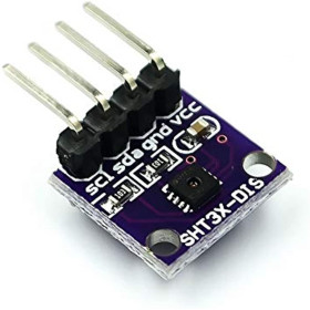
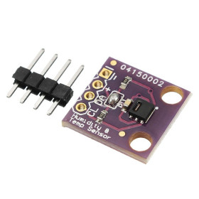
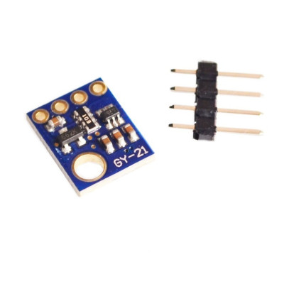
Temperature and Humidity Sensor SHT21 GY-21, High Precision, I2C Interface, 3-5V, 0-100%RH
Ideal for accurate temperature and humidity monitoring in IoT projects and automation, this SHT21 module provides stable and fast measurements, I2C communication for easy integration with Arduino and Raspberry Pi, low power consumption for long-term operation, and a compact breakout format suitable for prototyping and installation in tight spaces.
Shipping by Wednesday 11 November
Buying this product earns you Ft176.56 in loyalty points.

International fast shipping within EU. Free Shipping for orders above 100 EUR in most EU countries.

We ship from our stock within 24H

You earn points with every order, worth 5%.
The GY-21 module combines the SHT21 digital sensor with a 3.3 V voltage regulator and level shifters on the I2C lines, on a very small board for measuring the temperature and relative humidity of the air. The output is digital and factory calibrated, so it requires no external analog-to-digital converter or adjustments, and the module is suitable for indoor weather stations, thermostats and hygrostats, and for monitoring greenhouses, warehouses and rooms with humidifiers or dehumidifiers.
The SHT21 sensor measures relative humidity in the range 0 - 100 %RH, with a typical accuracy of ±2 %RH and a resolution of up to 12 bits, and temperature between -40 and 125 °C, with a typical accuracy of ±0.3 °C and a resolution of up to 14 bits. Communication is over the I2C bus, at the fixed address 0x40, with a clock frequency of up to 400 kHz. The maximum conversion time is 85 ms for temperature (14 bits) and 29 ms for humidity (12 bits), and each value read is accompanied by a CRC-8 checksum. The sensor has low current consumption, 0.15 µA at rest.
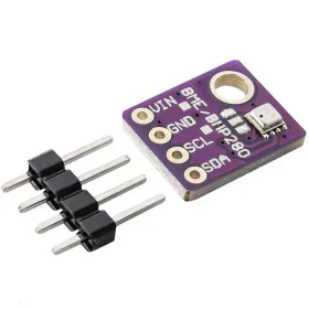
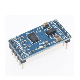
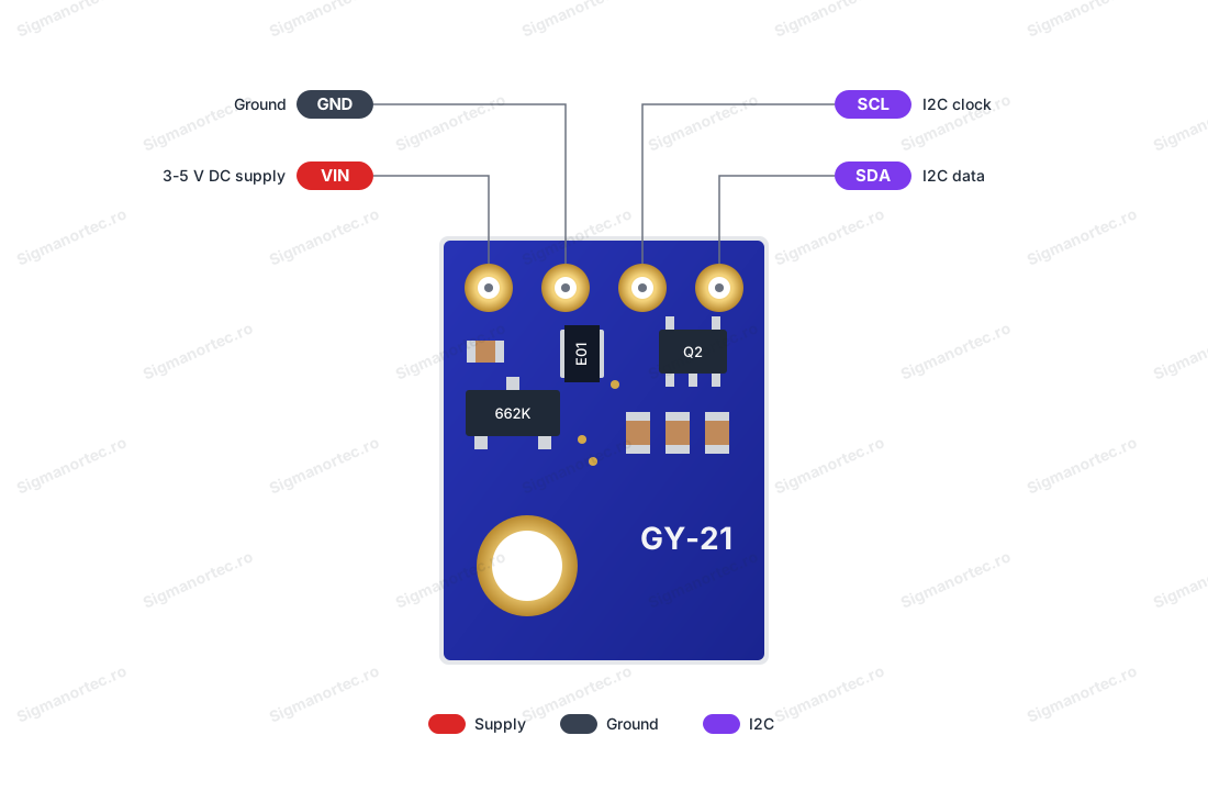
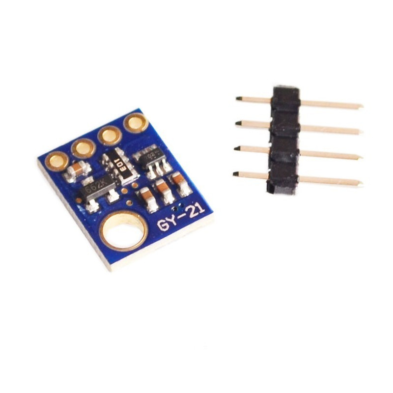
The main features include the 3.3 V regulator marked 662K, the transistors for logic level shifting on the SDA and SCL lines, the pull-up resistors for I2C, the mounting hole and the 4 pads for the VIN, GND, SCL and SDA pins, for which a 4-pin header is supplied that the user solders on. The module is powered at 3 - 5 VDC through the VIN pin.
Through the I2C interface, the module connects directly to Arduino, ESP32, ESP8266, STM32, Raspberry Pi and other platforms with an I2C bus, with both 3.3 V and 5 V logic.
Specifications:
Supply voltage: 3 - 5 VDC (VIN pin)
SHT21 sensor current: 0.15 µA at rest, up to 330 µA during measurement
Sensor: SHT21
Interface: I2C
I2C address: 0x40 (fixed)
I2C clock frequency: up to 400 kHz
Humidity range: 0 - 100 %RH
Humidity accuracy: ±2 %RH (typical)
Humidity resolution: up to 12 bits
Temperature range: -40 - 125 °C
Temperature accuracy: ±0.3 °C (typical)
Temperature resolution: up to 14 bits
Maximum measurement time: 85 ms for temperature (14 bits), 29 ms for humidity (12 bits)
Output: Digital, calibrated, with CRC-8 checksum
Dimensions: 10 x 13 mm
Layout:
| Element | Function |
|---|---|
| SHT21 sensor | Measures the temperature and relative humidity and sends the values digitally, via I2C, at address 0x40. |
| 662K regulator | Supplies 3.3 V to the sensor from the voltage applied to the VIN pin. |
| Level shifting transistors | Adapt the logic level of the SDA and SCL lines between the sensor and the connected microcontroller. |
| Pull-up resistors | Keep the SDA and SCL lines at a high level when the bus is free, so external resistors are not needed for a single module. |
| VIN, GND, SCL, SDA pads | Connecting the module. The included 4-pin header is soldered to these pads. |
| Mounting hole | Fixing the board to a support. |
Pinout:
| Connector | Pin | Function |
|---|---|---|
| 4-pin header | VIN | Power supply 3 - 5 VDC |
| 4-pin header | GND | Ground |
| 4-pin header | SCL | I2C clock line |
| 4-pin header | SDA | I2C data line |
Usage:
Solder the included 4-pin header into the module pads, then check the markings on the board, because on some versions the power pin is marked VCC instead of VIN, with the same role.
Connect VIN to the 3.3 V or 5 V pin of the microcontroller, depending on its operating voltage, GND to the common ground, SDA to the SDA line and SCL to the SCL line. On the Arduino Uno, the I2C lines are pins A4 (SDA) and A5 (SCL).
Do not apply a voltage higher than 5 V to VIN and observe the power supply polarity.
Do not connect two identical modules on the same I2C bus, because the address 0x40 is fixed.
For a measurement, send the command 0xF3 for temperature or 0xF5 for humidity to address 0x40, in no-clock-stretching mode, wait at least 85 ms for temperature and 29 ms for humidity, then read three bytes: two data bytes and one CRC byte.
Check the CRC-8 checksum (polynomial 0x31, initial value 0) and ignore the reading if it does not match. Clear the last two bits of the 16-bit value, then calculate the temperature in °C with the formula -46.85 + 175.72 x S / 65536 and the humidity in %RH with the formula -6 + 125 x S / 65536.
To check that the module works, gently touch the sensor with your finger or blow warm, humid air over it, and the readings will rise within a short time.
For stable results, mount the module away from heat sources, including the development board and its voltage regulators, use short wires on SDA and SCL, and avoid direct contact of the sensor with water, condensation or aggressive vapours.
- Supply voltage
- 3-5 V DC
- Dimensions
- 10 x 13 mm
- Interface
- I2C
- Output type
- Digital
- Power consumption
- 0.15 µA idle, up to 330 µA while measuring
- Sensor
- SHT21
- I2C address
- 0x40
- Temperature measuring range
- -40-125 °C
Produs destinat utilizarii in proiecte electronice, automatizari, prototipare, educatie si cercetare.
Produsul trebuie utilizat numai conform specificatiilor tehnice mentionate in descriere si/sau in documentatia produsului.
Avertismente generale de siguranta:
Nu utilizati produsul la tensiuni, curenti sau temperaturi peste valorile specificate.
Montajul si conectarea trebuie realizate de persoane cu cunostinte tehnice minime in domeniul electric/electronic.
Evitati scurtcircuitele, inversarea polaritatii si conectarea gresita a alimentarii.
Nu lasati produsul alimentat nesupravegheat in timpul testelor.
Produsul nu este jucarie si nu este destinat copiilor.
Pentru modulele electronice, se recomanda utilizarea in carcase, panouri sau montaje protejate, dupa caz.
Identificare produs:
Denumirea produsului, codul/SKU-ul si caracteristicile tehnice sunt mentionate in pagina produsului si/sau pe eticheta ambalajului.
Producator / Importator / Distribuitor:
Sigmanortec S.R.L.
Calea Bucuresti nr. 9, Targu Jiu, Gorj, Romania
E-mail: [email protected]
Website: www.sigmanortec.ro
Persoana responsabila in UE:
Sigmanortec S.R.L.
Calea Bucuresti nr. 9, Targu Jiu, Gorj, Romania
E-mail: [email protected]
Documentatie si siguranta:
Pentru informatii suplimentare, fise tehnice, declaratii de conformitate sau instructiuni, ne puteti contacta la [email protected].
Reviews (1) - Review moderation

/*
  SHT21 / GY-21 temperature and humidity test

  Board (Arduino IDE, Tools > Board): Arduino Uno
  Board package: Arduino AVR Boards (comes with the Arduino IDE)

  Libraries: none to install, only the built-in Wire library is used.

  Wiring (the GY-21 module has its own 3.3 V regulator, level shifters
  and pull-up resistors on the I2C lines):
    Module VIN -> Arduino 5V
    Module GND -> Arduino GND
    Module SDA -> Arduino A4
    Module SCL -> Arduino A5
*/

#include <Wire.h>

// I2C address of the sensor
const uint8_t SHT21_ADDRESS = 0x40;

// Sensor commands
const uint8_t CMD_TRIGGER_TEMP_NO_HOLD = 0xF3; // start temperature measurement
const uint8_t CMD_TRIGGER_HUM_NO_HOLD  = 0xF5; // start humidity measurement
const uint8_t CMD_SOFT_RESET           = 0xFE; // reset the sensor

// Waiting times in milliseconds, slightly above the maximum conversion time
const uint16_t TEMP_WAIT_MS = 100; // 14 bit temperature
const uint16_t HUM_WAIT_MS  = 40;  // 12 bit humidity

// CRC-8 with polynomial 0x31, start value 0
uint8_t crc8(const uint8_t *data, uint8_t length) {
  uint8_t crc = 0;
  for (uint8_t i = 0; i < length; i++) {
    crc ^= data[i];
    for (uint8_t bit = 0; bit < 8; bit++) {
      if (crc & 0x80) {
        crc = (crc << 1) ^ 0x31;
      } else {
        crc = crc << 1;
      }
    }
  }
  return crc;
}

// Send a measurement command, wait, read 3 bytes and check the CRC
bool readRaw(uint8_t command, uint16_t waitMs, uint16_t &raw) {
  Wire.beginTransmission(SHT21_ADDRESS);
  Wire.write(command);
  if (Wire.endTransmission() != 0) {
    return false; // sensor did not acknowledge
  }

  delay(waitMs); // wait for the conversion to finish

  if (Wire.requestFrom(SHT21_ADDRESS, (uint8_t)3) != 3) {
    return false; // fewer than 3 bytes received
  }

  uint8_t data[3];
  for (uint8_t i = 0; i < 3; i++) {
    data[i] = Wire.read();
  }

  if (crc8(data, 2) != data[2]) {
    return false; // checksum error
  }

  raw = ((uint16_t)data[0] << 8) | data[1];
  raw &= 0xFFFC; // clear the two status bits
  return true;
}

void setup() {
  Serial.begin(9600);
  Wire.begin();
  Serial.println("SHT21 / GY-21 test started");

  // Check that the sensor answers at its address
  Wire.beginTransmission(SHT21_ADDRESS);
  if (Wire.endTransmission() != 0) {
    Serial.println("Sensor not found at address 0x40, check wiring");
    while (true) {
      delay(1000); // stop here
    }
  }
  Serial.println("Sensor found at address 0x40");

  // Soft reset, the sensor needs up to 15 ms to restart
  Wire.beginTransmission(SHT21_ADDRESS);
  Wire.write(CMD_SOFT_RESET);
  Wire.endTransmission();
  delay(20);
}

void loop() {
  uint16_t rawTemperature = 0;
  uint16_t rawHumidity = 0;

  if (readRaw(CMD_TRIGGER_TEMP_NO_HOLD, TEMP_WAIT_MS, rawTemperature) &&
      readRaw(CMD_TRIGGER_HUM_NO_HOLD, HUM_WAIT_MS, rawHumidity)) {

    // Convert raw values to physical values
    float temperatureC = -46.85 + 175.72 * (float)rawTemperature / 65536.0;
    float humidityRH = -6.0 + 125.0 * (float)rawHumidity / 65536.0;

    // Limit humidity to the physical range
    if (humidityRH < 0.0) humidityRH = 0.0;
    if (humidityRH > 100.0) humidityRH = 100.0;

    Serial.print("Temperature: ");
    Serial.print(temperatureC, 2);
    Serial.print(" C, Humidity: ");
    Serial.print(humidityRH, 1);
    Serial.println(" %RH");
  } else {
    Serial.println("Read error (no answer or CRC mismatch)");
  }

  delay(2000); // one reading every 2 seconds
}
This tutorial uses the Arduino Uno board, because the GY-21 module is an I2C sensor that necessarily needs a microcontroller to query it. The module carries the SHT21 sensor and measures the temperature and relative humidity of the air, with a digital output that is already calibrated. You will use it in indoor weather stations, for monitoring a greenhouse, a warehouse or a room with a humidifier, and in thermostats and hygrostats built by yourself.
Unlike an analog sensor, the SHT21 does not require calibration and does not need an external analog-to-digital converter. The microcontroller sends a command over two wires and receives back the measured value, accompanied by a checksum. In the steps below you will connect the module, read the values with a minimal library (only Wire) and see how the raw numbers are converted into degrees Celsius and humidity percentages.
How it works:
Inside the SHT21 there is a polymer capacitive element for humidity and a bandgap type temperature sensor. An integrated analog-to-digital converter turns both quantities into numbers, and the processing circuit applies the factory calibration. The result comes out on the I2C bus, at the fixed address 0x40, with a clock frequency of at most 400 kHz.
A measurement has four stages. The microcontroller sends the address 0x40 and a command: 0xF3 starts the temperature measurement and 0xF5 starts the humidity measurement, both in no hold master mode (no hold master). Then it waits for the conversion time, at most 85 ms for temperature at 14 bits and at most 29 ms for humidity at 12 bits. After that it reads three bytes: two data bytes and one CRC byte. Finally, it calculates the real value from the raw number.
The last two bits of the second byte are status bits and must be cleared before the calculation. With the raw number S, the formulas are: temperature in °C = -46.85 + 175.72 x S / 65536 and relative humidity in %RH = -6 + 125 x S / 65536. The number 65536 is 2 to the power of 16, that is, the number of values a 16-bit word can have. Example: for S = 26000 the temperature is -46.85 + 175.72 x 26000 / 65536 = 22.86 °C, and for S = 31000 the humidity is -6 + 125 x 31000 / 65536 = 53.13 %RH.
The CRC-8 checksum uses the polynomial x to the 8 + x to the 5 + x to the 4 + 1 (in code, the constant 0x31) and starts from the value 0. If the calculated CRC differs from the received one, the reading was affected by noise and must be ignored.
Wiring:
The SHT21 chip works at 2.1 - 3.6 V, but the GY-21 module has on board a 3.3 V regulator (marked 662K) and level shifters with transistors on the I2C lines. That is why you power it directly from the 5V pin of the Arduino Uno, and the SDA and SCL lines connect directly, without an external logic level converter. The module also has its own pull-up resistors, so for a single module you do not need external resistors. First solder the 4-pin connector included on the module board. The pins on the module are, in order, VIN, GND, SCL and SDA.
| Product pin | Connects to | Role |
|---|---|---|
| VIN | 5V pin Arduino Uno | Power supply for the module |
| GND | GND Arduino Uno | Common ground |
| SDA | A4 pin Arduino Uno | I2C data line |
| SCL | A5 pin Arduino Uno | I2C clock line |
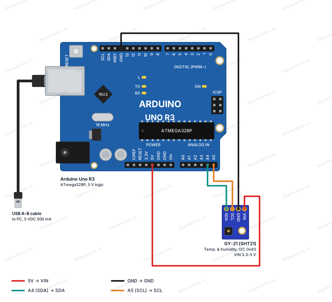
On the Arduino Uno, pins A4 and A5 are the same lines as the SDA and SCL pins on the right side of the top header, so you can use either of them. The board is powered through the USB cable from the computer. On some versions of the module the power pin is marked VCC instead of VIN, the role is the same. Check the markings on the board before soldering and connecting.
Board and libraries:
In the Arduino IDE select at Tools > Board the Arduino Uno board, from the Arduino AVR Boards package, which comes installed with the Arduino IDE. If it does not appear in the list, install it from Tools > Board > Boards Manager, searching for Arduino AVR Boards. At Tools > Port choose the serial port of the board.
The program uses only the Wire library, which comes with the Arduino IDE, so no library needs to be installed. The communication with the sensor is written directly, which allows you to see each step of the protocol.
The code:
The program below reads the temperature and humidity once every 2 seconds, checks the checksum and displays the result on the serial monitor.
/*
  SHT21 / GY-21 temperature and humidity example
  Board (Arduino IDE, Tools > Board): Arduino Uno
  Board package: Arduino AVR Boards (comes with the Arduino IDE)
  Libraries: none to install, only the built-in Wire library is used.
  Wiring (the GY-21 module has its own 3.3 V regulator, level shifters
  and pull-up resistors on the I2C lines):
    Module VIN -> Arduino 5V
    Module GND -> Arduino GND
    Module SDA -> Arduino A4
    Module SCL -> Arduino A5
*/
#include <Wire.h>
// I2C address of the sensor
const uint8_t SHT21_ADDRESS = 0x40;
// Sensor commands
const uint8_t CMD_TRIGGER_TEMP_NO_HOLD = 0xF3; // start temperature measurement
const uint8_t CMD_TRIGGER_HUM_NO_HOLD  = 0xF5; // start humidity measurement
const uint8_t CMD_SOFT_RESET           = 0xFE; // reset the sensor
// Waiting times in milliseconds, slightly above the maximum conversion time
const uint16_t TEMP_WAIT_MS = 100; // 14 bit temperature
const uint16_t HUM_WAIT_MS  = 40;  // 12 bit humidity
// CRC-8 with polynomial 0x31, start value 0
uint8_t crc8(const uint8_t *data, uint8_t length) {
  uint8_t crc = 0;
  for (uint8_t i = 0; i < length; i++) {
    crc ^= data[i];
    for (uint8_t bit = 0; bit < 8; bit++) {
      if (crc & 0x80) {
        crc = (crc << 1) ^ 0x31;
      } else {
        crc = crc << 1;
      }
    }
  }
  return crc;
}
// Send a measurement command, wait, read 3 bytes and check the CRC
bool readRaw(uint8_t command, uint16_t waitMs, uint16_t &raw) {
  Wire.beginTransmission(SHT21_ADDRESS);
  Wire.write(command);
  if (Wire.endTransmission() != 0) {
    return false; // sensor did not acknowledge
  }
  delay(waitMs); // wait for the conversion to finish
  if (Wire.requestFrom(SHT21_ADDRESS, (uint8_t)3) != 3) {
    return false; // fewer than 3 bytes received
  }
  uint8_t data[3];
  for (uint8_t i = 0; i < 3; i++) {
    data[i] = Wire.read();
  }
  if (crc8(data, 2) != data[2]) {
    return false; // checksum error
  }
  raw = ((uint16_t)data[0] << 8) | data[1];
  raw &= 0xFFFC; // clear the two status bits
  return true;
}
void setup() {
  Serial.begin(9600);
  Wire.begin();
  Serial.println("SHT21 / GY-21 test started");
  // Check that the sensor answers at its address
  Wire.beginTransmission(SHT21_ADDRESS);
  if (Wire.endTransmission() != 0) {
    Serial.println("Sensor not found at address 0x40, check wiring");
    while (true) {
      delay(1000); // stop here
    }
  }
  Serial.println("Sensor found at address 0x40");
  // Soft reset, the sensor needs up to 15 ms to restart
  Wire.beginTransmission(SHT21_ADDRESS);
  Wire.write(CMD_SOFT_RESET);
  Wire.endTransmission();
  delay(20);
}
void loop() {
  uint16_t rawTemperature = 0;
  uint16_t rawHumidity = 0;
  if (readRaw(CMD_TRIGGER_TEMP_NO_HOLD, TEMP_WAIT_MS, rawTemperature) &&
      readRaw(CMD_TRIGGER_HUM_NO_HOLD, HUM_WAIT_MS, rawHumidity)) {
    // Convert raw values to physical values
    float temperatureC = -46.85 + 175.72 * (float)rawTemperature / 65536.0;
    float humidityRH = -6.0 + 125.0 * (float)rawHumidity / 65536.0;
    // Limit humidity to the physical range
    if (humidityRH < 0.0) humidityRH = 0.0;
    if (humidityRH > 100.0) humidityRH = 100.0;
    Serial.print("Temperature: ");
    Serial.print(temperatureC, 2);
    Serial.print(" C, Humidity: ");
    Serial.print(humidityRH, 1);
    Serial.println(" %RH");
  } else {
    Serial.println("Read error (no answer or CRC mismatch)");
  }
  delay(2000); // one reading every 2 seconds
}
How the code works:
At the beginning the sensor address (SHT21_ADDRESS, 0x40), the measurement commands (CMD_TRIGGER_TEMP_NO_HOLD and CMD_TRIGGER_HUM_NO_HOLD) and the reset command (CMD_SOFT_RESET) are defined. The constants TEMP_WAIT_MS and HUM_WAIT_MS set how long the program waits after the command, slightly above the maximum conversion times of the sensor.
The crc8 function calculates the checksum with the polynomial 0x31, starting from the value 0, over the two data bytes received. The readRaw function sends the command, waits for the conversion, requests three bytes with Wire.requestFrom, compares the calculated CRC with the received one and, if everything is correct, forms the raw number from the two data bytes and clears the two status bits with the mask 0xFFFC. The function returns false if the sensor does not respond, if fewer than 3 bytes are received or if the checksum does not match.
In setup the serial port is started at 9600 baud and the I2C bus with Wire.begin. The program then checks whether the sensor responds at address 0x40 and, if it does not respond, stops with a message about checking the connections. In case of success, it sends the software reset command and waits 20 ms, the time the sensor needs to restart.
In loop the temperature (rawTemperature) and the humidity (rawHumidity) are requested one after the other. The raw values are converted into temperatureC and humidityRH with the formulas from the section about how it works, and the humidity is limited to the range 0 - 100 %RH. The result is displayed on the serial monitor, and on a faulty reading an error message appears. The 2 second pause between measurements is done with delay(2000).
Result:
Open the serial monitor from the Arduino IDE (Tools > Serial Monitor) and set the speed to 9600 baud. Every 2 seconds a line appears with the measured temperature and humidity, as in the example below.
SHT21 / GY-21 test started
Sensor found at address 0x40
Temperature: 23.41 C, Humidity: 48.7 %RH
Temperature: 23.43 C, Humidity: 48.6 %RH
Temperature: 23.44 C, Humidity: 48.8 %RH
Temperature: 23.46 C, Humidity: 51.9 %RH
Temperature: 23.52 C, Humidity: 56.3 %RH
Temperature: 23.49 C, Humidity: 53.1 %RH
Temperature: 23.45 C, Humidity: 49.5 %RH
Common problems:
The message that the sensor was not found at address 0x40 appears. The most frequent cause is a wrong connection or a missing common ground. Check that SDA goes to A4 and SCL to A5, that they are not swapped, that GND is connected and that the connector pins are soldered correctly on the module board.
The reading error message appears (no response or wrong CRC). The cause is usually noise on long wires or poor contacts. Shorten the SDA and SCL wires, keep them away from power cables or motors and check the solder joints.
The displayed temperature is higher than the real one. The sensor picks up heat from nearby boards, for example from the regulator of the Arduino board. Mount the module at a distance, preferably on longer wires, and let it stabilize for a few minutes.
The humidity stays at 100 %RH or rises suddenly. The sensor has been exposed to condensation or water. Let it dry in a ventilated place and, when mounting, protect it from splashes and from direct contact with liquids.
Nothing appears on the serial monitor. Check that you chose the correct port at Tools > Port, that the selected board is Arduino Uno and that the serial monitor speed is 9600 baud.
Limitations and tips:
The typical accuracy is ±2 %RH for humidity and ±0.3 °C for temperature, in the ranges 0 - 100 %RH and -40 - 125 °C. The sensor is not designed for measuring in liquids or in the presence of condensation and does not react instantly, because the humidity stabilizes in a few seconds. The address 0x40 is fixed, so only one such module can exist on the same I2C bus.
A reading every 2 seconds is enough for most ambient applications. Further on you can display the values on an OLED or LCD display, log them on an SD card or control a relay for a humidifier or for a ventilation according to the desired thresholds, with a hysteresis of a few percent to avoid frequent switching.