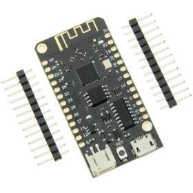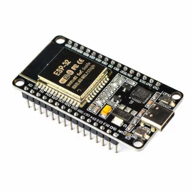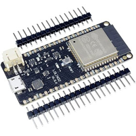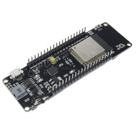

Product images are for informational purposes only and may vary slightly depending on the batch and supplier. Product specifications and prices may be subject to change without notice. We do our best to provide accurate and complete product specifications, but they may not be completely accurate. If you encounter any such situation, please let us know.
The product is intended for specialists and requires qualified and authorized personnel. The product does not include assembly/use instructions . Putting the product into operation by unqualified persons leads to the loss of the warranty according to the Terms and Conditions on the site.
The specified technical parameters (current, power, etc.) represent maximum allowable values under ideal operating conditions. For safe use and optimal lifespan, it is recommended to operate the product continuously at no more than 50% of the specified maximum values.
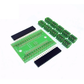
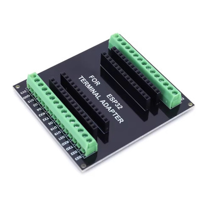
ESP32 expansion terminal, 30-pin, 2x15 pins, screw terminals
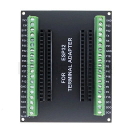
The 30-pin ESP32 expansion board brings all your GPIO to screw terminals for quick and secure wiring without soldering. It allows for easy mounting and dismounting of the board, keeps connections stable in prototyping and IoT projects, is compatible with most 2x15-pin ESP32 boards, and provides clear pin access for testing and integration.
Buying this product earns you 0.85 RON in loyalty points.

International fast shipping within EU. Free Shipping for orders above 100 EUR in most EU countries.

We ship from our stock within 24H

You earn points with every order, worth 5%.
The ESP32 expansion terminal is a passive adapter board that brings out the pins of a 30-pin ESP32 development board to two screw terminal blocks. Connections are made without soldering, directly with wires inserted into the terminals. It is suitable for IoT projects, home automation, prototypes with many GPIO connections, and setups that are changed frequently.
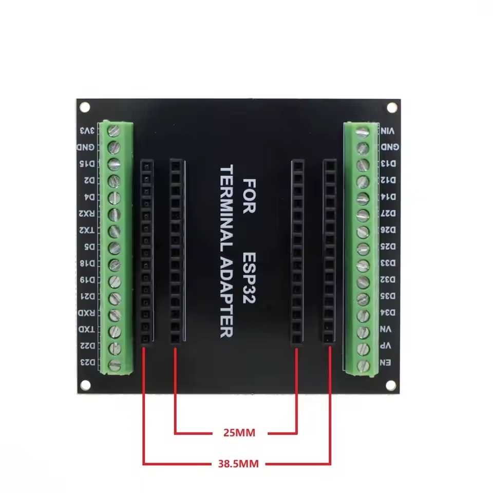
The adapter has 30 connection positions, arranged in two rows of 15 each (2x15). Each pin of the ESP32 board is brought out to a terminal labeled on the board, for example 3V3, GND, D15, D2, D4, RX2, TX2, D5, D18, D19, D21, RXD, TXD, D22 and D23 on one row. The ESP32 board is inserted into sockets and can be removed easily, without needing to disconnect the wires or modules attached to the terminals.
Among the main features are two 15-position screw terminal blocks, female sockets for the ESP32 board pins arranged in two rows on each side, silkscreen markings for each pin, and four mounting holes in the corners. The adapter has no own power supply, and the ESP32 board is powered in the usual way, through the USB port or through the power pins.
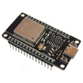
The adapter is compatible with 30-pin ESP32 development boards, for example the ESP-WROOM-32 DevKit1 with WiFi and Bluetooth BLE, including variants with CH340C and USB-C. Before mounting, check the distance between the board’s pin rows and the correspondence of the markings.
Specifications:
Compatibility: ESP32 development boards, especially 30-pin ESP32 boards
Type: Passive adapter with screw terminals
Pin count: 30 (2x15)
Connectors: Screw terminal block, female sockets for the ESP32 board
Mounting: 4 corner holes
Layout:
| Element | Function |
|---|---|
| Screw terminal block, 15 positions, markings 3V3 - D23 | Access to the 3V3, GND, D15, D2, D4, RX2, TX2, D5, D18, D19, D21, RXD, TXD, D22 and D23 pins of the ESP32 board. The wire is inserted into the terminal and secured with the screw. |
| Screw terminal block, 15 positions, markings EN - VIN | Access to the pins on the other side of the ESP32 board, from EN to VIN. The wire is inserted into the terminal and secured with the screw. |
| Female sockets | Accept the pins of the ESP32 board, in two rows on each side. The board can be inserted and removed without disconnecting the wires from the terminals. |
| Silkscreen markings | The name of each pin, printed next to the terminal. The markings on the adapter must match those on the ESP32 board. |
| Mounting holes | Fixing the adapter in a enclosure or on a support. |
Pinout:
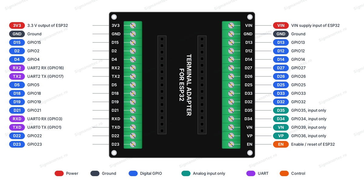
| Connector | Pin | Function |
|---|---|---|
| Terminal 1 | 3V3 | 3.3 V output of the ESP32 board |
| Terminal 1 | GND | Ground |
| Terminal 1 | D15 | GPIO15 |
| Terminal 1 | D2 | GPIO2 |
| Terminal 1 | D4 | GPIO4 |
| Terminal 1 | RX2 | UART2 reception (GPIO16) |
| Terminal 1 | TX2 | UART2 transmission (GPIO17) |
| Terminal 1 | D5 | GPIO5 |
| Terminal 1 | D18 | GPIO18 |
| Terminal 1 | D19 | GPIO19 |
| Terminal 1 | D21 | GPIO21 |
| Terminal 1 | RXD | UART0 reception (GPIO3) |
| Terminal 1 | TXD | UART0 transmission (GPIO1) |
| Terminal 1 | D22 | GPIO22 |
| Terminal 1 | D23 | GPIO23 |
| Terminal 2 | EN | Enable (reset) pin of the ESP32 board |
| Terminal 2 | VP | GPIO36, input only |
| Terminal 2 | VN | GPIO39, input only |
| Terminal 2 | D34 | GPIO34, input only |
| Terminal 2 | D35 | GPIO35, input only |
| Terminal 2 | D32 | GPIO32 |
| Terminal 2 | D33 | GPIO33 |
| Terminal 2 | D25 | GPIO25 |
| Terminal 2 | D26 | GPIO26 |
| Terminal 2 | D27 | GPIO27 |
| Terminal 2 | D14 | GPIO14 |
| Terminal 2 | D12 | GPIO12 |
| Terminal 2 | D13 | GPIO13 |
| Terminal 2 | GND | Ground |
| Terminal 2 | VIN | VIN power pin of the ESP32 board |
Usage:
Disconnect the ESP32 board from power and from the USB cable before mounting it in the adapter or removing it.
Check the distance between the ESP32 board’s pin rows and the adapter sockets, because 30-pin ESP32 boards may have different row spacing.
Verify that the pin markings on the ESP32 board match those on the adapter, then insert the board into the correct sockets, with all pins fully inserted and without bent pins.
Strip the wire ends over a short length, insert them into the desired terminals and tighten the screws until the wire is securely fixed.
Connect only one wire or one conductor to each terminal, and route the ground wires to the GND terminals.
Do not apply voltages higher than 3.3 V to the GPIO pins and do not power heavy loads directly from GPIO pins.
Use the VP, VN, D34 and D35 pins only as inputs, because these ESP32 GPIOs cannot be configured as outputs.
Avoid holding the D2, D5, D12 and D15 pins high or heavily loading them at startup, because they are used by the ESP32 to select the boot mode.
Power the ESP32 board through its USB port or through the VIN pin, observing the polarity and voltage accepted by the board.
Program the ESP32 board as usual, from Arduino IDE or ESP-IDF, with the board mounted in the adapter or removed from it.
For stable connections, periodically check the screw tightness and use wires with a cross-section suitable for the terminals.
- Type
- Passive adapter with screw terminals
- Number of pins
- 30 (2 x 15)
- Connector type
- Screw terminal, female headers
- Mounting
- 4 corner holes
- Compatibility
- ESP32 boards with 30 pins
Produs destinat utilizarii in proiecte electronice, automatizari, prototipare, educatie si cercetare.
Produsul trebuie utilizat numai conform specificatiilor tehnice mentionate in descriere si/sau in documentatia produsului.
Avertismente generale de siguranta:
Nu utilizati produsul la tensiuni, curenti sau temperaturi peste valorile specificate.
Montajul si conectarea trebuie realizate de persoane cu cunostinte tehnice minime in domeniul electric/electronic.
Evitati scurtcircuitele, inversarea polaritatii si conectarea gresita a alimentarii.
Nu lasati produsul alimentat nesupravegheat in timpul testelor.
Produsul nu este jucarie si nu este destinat copiilor.
Pentru modulele electronice, se recomanda utilizarea in carcase, panouri sau montaje protejate, dupa caz.
Identificare produs:
Denumirea produsului, codul/SKU-ul si caracteristicile tehnice sunt mentionate in pagina produsului si/sau pe eticheta ambalajului.
Producator / Importator / Distribuitor:
Sigmanortec S.R.L.
Calea Bucuresti nr. 9, Targu Jiu, Gorj, Romania
E-mail: [email protected]
Website: www.sigmanortec.ro
Persoana responsabila in UE:
Sigmanortec S.R.L.
Calea Bucuresti nr. 9, Targu Jiu, Gorj, Romania
E-mail: [email protected]
Documentatie si siguranta:
Pentru informatii suplimentare, fise tehnice, declaratii de conformitate sau instructiuni, ne puteti contacta la [email protected].