
Product images are for informational purposes only and may vary slightly depending on the batch and supplier. Product specifications and prices may be subject to change without notice. We do our best to provide accurate and complete product specifications, but they may not be completely accurate. If you encounter any such situation, please let us know.
The product is intended for specialists and requires qualified and authorized personnel. The product does not include assembly/use instructions . Putting the product into operation by unqualified persons leads to the loss of the warranty according to the Terms and Conditions on the site.
The specified technical parameters (current, power, etc.) represent maximum allowable values under ideal operating conditions. For safe use and optimal lifespan, it is recommended to operate the product continuously at no more than 50% of the specified maximum values.
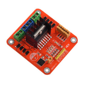
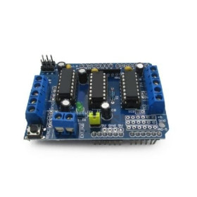
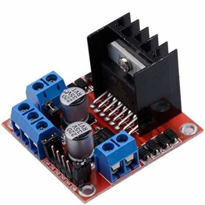
Dual H-Bridge L298N Module, 2 DC Motors, 5-35V, 2A per Channel
Dual H-bridge module with the L298N circuit for direction and speed control of two DC motors or one bipolar stepper motor. Motor supply 5 - 35 VDC, up to 2 A per channel, PWM inputs up to 40 kHz, integrated 5 V regulator and heatsink on the circuit. Compatible with Arduino and other development boards.
Shipping by Wednesday 11 November
Buying this product earns you 0.71 RON in loyalty points.

International fast shipping within EU. Free Shipping for orders above 100 EUR in most EU countries.

We ship from our stock within 24H

You earn points with every order, worth 5%.
The L298N dual H-bridge module is a motor driver that allows direction and speed control of two DC motors or of one bipolar stepper motor. The module receives logic signals from a microcontroller and converts them into current for the motors, which makes it suitable for mobile robots, remote-controlled cars, actuation mechanisms, simple 3D printers and other mechatronics projects.
The main circuit is the L298N, a dual H-bridge with two independent channels, each able to supply up to 2 A to a motor. The motors are powered at 5 - 35 VDC, while the logic section operates at 5 V. The direction of each motor is set by two inputs (IN1 and IN2 for motor A, IN3 and IN4 for motor B), and the speed is adjusted by a PWM signal on the enable inputs ENA and ENB, with a frequency of up to 40 kHz.
The main features include the heatsink mounted on the L298N circuit, the 78M05 5 V regulator with the 5V-EN activation jumper, the ENA and ENB jumpers for permanent activation of the channels, screw terminals for the motors and power supply, eight protection diodes for inductive loads, two electrolytic filter capacitors, an indicator LED and four mounting holes. The motors are powered at the +12V and GND terminals, and the 5 V regulator can also power the logic of the board or of the microcontroller when the supply voltage is lower than 12 V.
Through its logic control inputs, the module is compatible with Arduino, ESP32, STM32, Raspberry Pi and other development boards that have digital outputs and PWM outputs.
Specifications:
Motor supply voltage: 5 - 35 VDC
Motor current: max. 2 A per channel
Driver circuit: L298N, dual H-bridge
Number of channels: 2
Controlled motors: 2 DC motors or 1 bipolar stepper motor
Logic voltage: 5 V
5 V regulator: 78M05, activated by the 5V-EN jumper, for motor supply below 12 V
Input logic levels: LOW maximum 1.5 V, HIGH from 2.3 V
Maximum PWM frequency: 40 kHz
Protection: 8 diodes for inductive loads
Connection: Screw terminals for motors and power supply, pins for control signals
Dimensions: 43 x 43 x 27 mm
Layout:
| Element | Function |
|---|---|
| L298N circuit with heatsink | The dual H-bridge that switches the current to the two motors. The heatsink dissipates the heat produced at high currents. |
| OUT1 / OUT2 terminal | Output for motor A or for coil A of a bipolar stepper motor. |
| OUT3 / OUT4 terminal | Output for motor B or for coil B of a bipolar stepper motor. |
| 3-position power terminal (+12V, GND, +5V) | The +12V input receives the motor supply of 5 - 35 VDC, GND is the common ground, and +5V is a 5 V output when the 5V-EN jumper is fitted and a 5 V input for the logic when the jumper is removed. |
| 5V-EN jumper | Fitted, it activates the 78M05 regulator that produces 5 V for the logic from the motor supply voltage, used when this is below 12 V. Removed, the regulator is disabled and the logic must be powered externally at 5 V on the +5V terminal. |
| 78M05 regulator | Produces the 5 V voltage for the logic section of the module. |
| ENA, IN1, IN2, IN3, IN4, ENB pins | Control inputs. IN1 and IN2 set the direction of motor A, IN3 and IN4 the direction of motor B, and ENA and ENB activate the respective channel and receive the PWM signal for speed. |
| ENA jumper | Fitted, it keeps channel A permanently enabled, and motor A runs at maximum speed when inputs IN1 and IN2 have different levels. Removed, the activation and speed of motor A are controlled through the ENA pin. |
| ENB jumper | Fitted, it keeps channel B permanently enabled, and motor B runs at maximum speed when inputs IN3 and IN4 have different levels. Removed, the activation and speed of motor B are controlled through the ENB pin. |
| Protection diodes (8 pcs.) | Absorb the reverse voltage generated by the motor coils when stopping or when changing direction, protecting the L298N circuit. |
| Electrolytic capacitors 220 uF / 35 V | Filter the motor supply voltage and the 5 V voltage. |
| Indicator LED | Lights up when the 5 V line of the module is powered. |
| Mounting holes | Fixing the module to the chassis. |
Pinout:
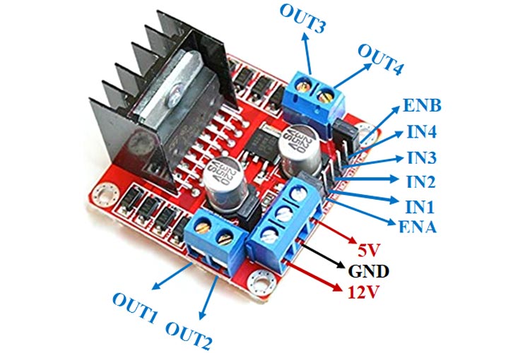
| Connector | Pin | Function |
|---|---|---|
| Power terminal | +12V | Motor supply 5 - 35 VDC |
| Power terminal | GND | Common ground for motors and logic |
| Power terminal | +5V | 5 V output with the 5V-EN jumper fitted, 5 V input for the logic without the jumper |
| Motor A terminal | OUT1 | Motor A output |
| Motor A terminal | OUT2 | Motor A output |
| Motor B terminal | OUT3 | Motor B output |
| Motor B terminal | OUT4 | Motor B output |
| Control pins | ENA | Motor A enable and PWM speed input |
| Control pins | IN1 | Motor A direction input |
| Control pins | IN2 | Motor A direction input |
| Control pins | IN3 | Motor B direction input |
| Control pins | IN4 | Motor B direction input |
| Control pins | ENB | Motor B enable and PWM speed input |
| ENA | IN1 | IN2 | Motor A state |
|---|---|---|---|
| 0 | X | X | Stopped, free rotation |
| 1 | 1 | 0 | Rotation in one direction |
| 1 | 0 | 1 | Rotation in the opposite direction |
Motor B works identically, with the pins ENB, IN3 and IN4.
Usage:
Connect motor A to the OUT1 and OUT2 terminals and motor B to the OUT3 and OUT4 terminals. For a bipolar stepper motor, connect one coil to OUT1 and OUT2 and the other coil to OUT3 and OUT4.
Power the motors at 5 - 35 VDC through the +12V and GND terminals, respecting the polarity. The voltage reaching the motor is about 2 V lower than the supply voltage, because part of it drops across the H-bridge.
To power the logic of the module, leave the 5V-EN jumper fitted when the motor supply voltage is below 12 V. In this case the +5V terminal becomes a 5 V output and can power the control board, and the indicator LED lights up.
For supply voltages of 12 V or higher, remove the 5V-EN jumper and power the logic with 5 V on the +5V terminal.
Do not apply voltage to the +5V terminal while the 5V-EN jumper is fitted and the regulator already powers the logic.
Connect the ground of the control board (GND) to the GND terminal of the module, so that the control signals have a common reference.
Connect the IN1, IN2, IN3 and IN4 inputs to four digital outputs of the control board and ENA and ENB to two PWM outputs. For example, on an Arduino Uno use ENA to D9, IN1 to D8, IN2 to D7, IN3 to D5, IN4 to D4 and ENB to D3.
For adjustable speed, remove the ENA and ENB jumpers and send a PWM signal to these inputs. With the jumpers fitted, the motors run only at maximum speed, and the control is limited to direction and stop.
Set the direction of a motor by placing a HIGH level on one of its inputs and a LOW level on the other. Inverting the levels reverses the direction of rotation.
Do not set both inputs of the same motor to HIGH at the same time, for example IN1 and IN2 or IN3 and IN4, because the module may be damaged. In programs, first bring the input that is being disabled to LOW and only then set the other input to HIGH.
At the first start, use a small PWM value and increase it gradually. If the motor does not turn, check the power supply, the common ground and the mounting of the ENA and ENB jumpers, and if the direction is opposite to the desired one, reverse the motor wires or the IN1 and IN2 levels.
For currents close to 2 A per channel, provide ventilation around the heatsink and avoid blocking the motor, because the circuit heats up.
For boards with 3.3 V logic, the control signals are recognized as HIGH level from 2.3 V, while the logic is still powered at 5 V.
- Supply voltage
- 5-35 V DC
- Dimensions
- 43 x 43 x 27 mm
- Type
- Dual H-bridge
- Output current
- max. 2 A per channel
- Logic voltage
- 5 V
- Protections
- 8 diodes for inductive loads
- Number of channels
- 2
- Integrated circuit
- L298N
Produs destinat utilizarii in proiecte electronice, automatizari, prototipare, educatie si cercetare.
Produsul trebuie utilizat numai conform specificatiilor tehnice mentionate in descriere si/sau in documentatia produsului.
Avertismente generale de siguranta:
Nu utilizati produsul la tensiuni, curenti sau temperaturi peste valorile specificate.
Montajul si conectarea trebuie realizate de persoane cu cunostinte tehnice minime in domeniul electric/electronic.
Evitati scurtcircuitele, inversarea polaritatii si conectarea gresita a alimentarii.
Nu lasati produsul alimentat nesupravegheat in timpul testelor.
Produsul nu este jucarie si nu este destinat copiilor.
Pentru modulele electronice, se recomanda utilizarea in carcase, panouri sau montaje protejate, dupa caz.
Identificare produs:
Denumirea produsului, codul/SKU-ul si caracteristicile tehnice sunt mentionate in pagina produsului si/sau pe eticheta ambalajului.
Producator / Importator / Distribuitor:
Sigmanortec S.R.L.
Calea Bucuresti nr. 9, Targu Jiu, Gorj, Romania
E-mail: [email protected]
Website: www.sigmanortec.ro
Persoana responsabila in UE:
Sigmanortec S.R.L.
Calea Bucuresti nr. 9, Targu Jiu, Gorj, Romania
E-mail: [email protected]
Documentatie si siguranta:
Pentru informatii suplimentare, fise tehnice, declaratii de conformitate sau instructiuni, ne puteti contacta la [email protected].
Reviews (11) - Review moderation

Nu l-am probat
ok
Un produs profesional
Produsul corespunde descrierii. Nu am fost atent la ce baterii am folosit si am crezut ca e defect, dar funcsioneaza aaa cum am dorit.
Face ce trebuie. Prea ok.
/*
  L298N dual H-bridge motor driver test
  Board: Arduino Uno (Tools > Board > Arduino AVR Boards > Arduino Uno)
  Libraries: none needed

  Wiring:
    L298N ENA -> D9 (PWM)    L298N IN1 -> D8    L298N IN2 -> D7
    L298N ENB -> D3 (PWM)    L298N IN3 -> D5    L298N IN4 -> D4
    L298N GND -> Arduino GND and the power supply minus
    L298N +12V -> motor power supply plus (5 - 35 VDC)
    Motor A on OUT1 / OUT2, motor B on OUT3 / OUT4
    Remove the ENA and ENB jumpers so PWM can control the speed
*/

const int ENA = 9;
const int IN1 = 8;
const int IN2 = 7;
const int ENB = 3;
const int IN3 = 5;
const int IN4 = 4;

// Run both motors in the same direction at a given PWM value
void driveBoth(int speed, bool forward) {
  // Set the inactive input LOW first, so both inputs are never HIGH together
  digitalWrite(forward ? IN2 : IN1, LOW);
  digitalWrite(forward ? IN1 : IN2, HIGH);
  digitalWrite(forward ? IN4 : IN3, LOW);
  digitalWrite(forward ? IN3 : IN4, HIGH);
  analogWrite(ENA, speed);
  analogWrite(ENB, speed);
}

// Stop both motors
void stopBoth() {
  analogWrite(ENA, 0);
  analogWrite(ENB, 0);
  digitalWrite(IN1, LOW);
  digitalWrite(IN2, LOW);
  digitalWrite(IN3, LOW);
  digitalWrite(IN4, LOW);
}

void setup() {
  pinMode(ENA, OUTPUT);
  pinMode(IN1, OUTPUT);
  pinMode(IN2, OUTPUT);
  pinMode(ENB, OUTPUT);
  pinMode(IN3, OUTPUT);
  pinMode(IN4, OUTPUT);
  Serial.begin(9600);
  Serial.println("L298N test started");
  stopBoth();
}

void loop() {
  Serial.println("Both motors forward, PWM 180");
  driveBoth(180, true);
  delay(2000);

  Serial.println("Both motors stopped");
  stopBoth();
  delay(1000);

  Serial.println("Both motors backward, PWM 180");
  driveBoth(180, false);
  delay(2000);

  Serial.println("Both motors stopped");
  stopBoth();
  delay(2000);
}
The L298N Dual H-Bridge module is a driver for DC motors, built around the L298N circuit. It can control two DC motors independently, in direction and speed, or one bipolar stepper motor. We find it in wheeled robots, remote-controlled cars, small conveyor belts and any project where a microcontroller must move a motor that draws more current than a board pin can provide.
In this tutorial we use an Arduino Uno R3, because the module needs a microcontroller to send it the control signals, and the 5 V logic of the Uno board matches the module inputs directly. We will control two TT geared motors, powered from a 9 VDC mains adapter.
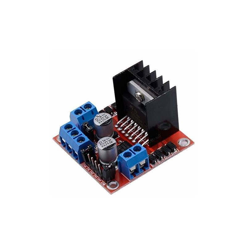
How it works:
A DC motor rotates in one direction or the other depending on the polarity of the voltage at its terminals. An H-bridge is a circuit with four switches that allows this polarity to be reversed from a logic signal. The L298N circuit contains two such bridges, so it can control two motors. For motor A the IN1 and IN2 inputs are used, and for motor B the IN3 and IN4 inputs.
The direction of rotation is chosen from the combination of levels on the two inputs of the motor. The HIGH combination on both inputs must never be used, because it can damage the module.
| IN1 (IN3) | IN2 (IN4) | Result |
|---|---|---|
| HIGH | LOW | The motor rotates forward |
| LOW | HIGH | The motor rotates backward |
| LOW | LOW | The motor is stopped |
| HIGH | HIGH | Forbidden in this circuit, do not use this combination |
Speed is adjusted with a PWM signal on the ENA (motor A) and ENB (motor B) pins. On the Arduino Uno, the analogWrite function accepts values from 0 to 255. The value 0 means motor off, and 255 means full continuous power. The average voltage reaching the motor is approximately Vmotor = (VS - Vdrop) x PWM / 255.
The L298N circuit internally loses part of the voltage, approximately 1.8 - 3.2 V at a current of 1 A and almost 5 V at 2 A. In our setup VS is 9 V, so at PWM 255 a motor drawing around 1 A receives approximately 7 V. TT motors are made for 3 - 6 V, so we limit the PWM value to 200. At 200, the average voltage is approximately 7 x 200 / 255 = 5.5 V, which is within the safe range of the motors.
The module also has a 78M05 regulator that can produce 5 V for the logic. With the 5V-EN jumper fitted, the regulator is active and the +5V terminal becomes a 5 V output, with a current of up to 0.5 A. This option is only used when the VS voltage is at most 12 V. Above 12 V the jumper is removed and the +5V terminal is powered from outside.
Connection:
Power the motors from a 9 VDC mains adapter with at least 1 A, connected through the jack adapter with screw terminals. The Arduino Uno board remains powered separately, through the USB cable. The adapter ground, the module ground and the Uno board ground must be joined, otherwise the control signals have no common reference and the motors will not respond correctly. The module inputs directly accept the 5 V logic level of the Uno board, so no level converter is needed.
| Product pin | Connect to | Role |
|---|---|---|
| +12V (VS) | Positive of the 9 VDC adapter | Motor power supply |
| GND | Negative of the 9 VDC adapter and the GND pin of the Uno board | Common ground |
| +5V | Not connected | With the 5V-EN jumper fitted it is a 5 V output, the Uno board remains powered through USB |
| ENA | D9 (PWM) | Speed of motor A |
| IN1 | D8 | Direction of motor A |
| IN2 | D7 | Direction of motor A |
| IN3 | D5 | Direction of motor B |
| IN4 | D4 | Direction of motor B |
| ENB | D3 (PWM) | Speed of motor B |
| OUT1 | Red wire of motor A | Motor A output |
| OUT2 | Black wire of motor A | Motor A output |
| OUT3 | Red wire of motor B | Motor B output |
| OUT4 | Black wire of motor B | Motor B output |
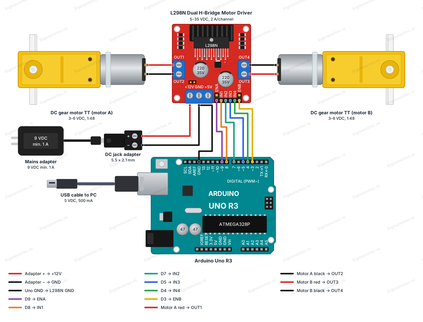
Remove the jumpers from ENA and ENB before powering the module, so that you can adjust the speed with PWM. The module already has two 220 uF capacitors on the board and the protection diodes for the motors, so no additional components need to be added.
Buttons, adjustments and indicators:
| Element | What it does | How to use it |
|---|---|---|
| 5V-EN jumper | Activates the 5 V regulator of the module | Leave it fitted when VS is 12 V or less, as in this tutorial. Remove it when VS exceeds 12 V, and the +5V terminal is powered from outside |
| ENA jumper | Ties the ENA input to 5 V, so motor A always runs at maximum speed | Remove it, so that pin D9 can control the speed through PWM |
| ENB jumper | Ties the ENB input to 5 V, so motor B always runs at maximum speed | Remove it, so that pin D3 can control the speed through PWM |
| Power LED | Indicates that power is present on the module | It lights up when the module receives voltage. If it stays off, check the adapter and the +12V terminal |
5V-EN jumper: start with it fitted. In this setup VS is 9 V, so the regulator can stay active. The +5V terminal is not connected to the Arduino, because the Uno board is powered through USB. Never power the +5V terminal from outside while the jumper is fitted.
ENA and ENB jumpers: remove both of them before the first start. With the jumper fitted, the respective motor runs permanently at maximum speed and the PWM command has no effect. The adjustment works when the motor speed changes while the program varies the analogWrite value.
Power LED: after connecting the adapter, it must light up immediately. It is the first thing to check when something does not work.
Board and libraries:
In the Arduino IDE select Tools > Board > Arduino AVR Boards > Arduino Uno. The Arduino AVR Boards package comes with the Arduino IDE, so it does not need to be installed separately. The program uses only the basic Arduino functions, so no library needs to be installed.
The code:
The program runs each motor forward and backward, at two speeds, and then runs both motors together. Copy it into the Arduino IDE and upload it to the Uno board.
/*
  L298N dual H-bridge motor driver demo
  Board: Arduino Uno (Tools > Board > Arduino AVR Boards > Arduino Uno)
  Libraries: none, the sketch uses only the core Arduino functions
  Wiring:
    ENA -> D9 (PWM)    IN1 -> D8    IN2 -> D7
    ENB -> D3 (PWM)    IN3 -> D5    IN4 -> D4
    L298N GND -> Arduino GND and the adapter minus
    L298N +12V -> adapter plus (9 VDC, min. 1 A)
    Remove the ENA and ENB jumpers so PWM can control the speed
*/
// Motor A pins
const int ENA = 9;   // Speed of motor A (PWM)
const int IN1 = 8;   // Direction input 1 of motor A
const int IN2 = 7;   // Direction input 2 of motor A
// Motor B pins
const int ENB = 3;   // Speed of motor B (PWM)
const int IN3 = 5;   // Direction input 1 of motor B
const int IN4 = 4;   // Direction input 2 of motor B
// Maximum PWM value, keeps 3-6 V motors in a safe range when VS is 9 V
const int MAX_PWM = 200;
// Run motor A at a given speed, forward or backward
void setMotorA(int speed, bool forward) {
  speed = constrain(speed, 0, MAX_PWM);   // Limit the speed
  // Write LOW first, so both inputs are never HIGH at the same time
  digitalWrite(forward ? IN2 : IN1, LOW);
  digitalWrite(forward ? IN1 : IN2, HIGH);
  analogWrite(ENA, speed);                // Apply the speed
  Serial.print("Motor A: ");
  Serial.print(forward ? "forward" : "backward");
  Serial.print(", PWM ");
  Serial.println(speed);
}
// Run motor B at a given speed, forward or backward
void setMotorB(int speed, bool forward) {
  speed = constrain(speed, 0, MAX_PWM);   // Limit the speed
  // Write LOW first, so both inputs are never HIGH at the same time
  digitalWrite(forward ? IN4 : IN3, LOW);
  digitalWrite(forward ? IN3 : IN4, HIGH);
  analogWrite(ENB, speed);                // Apply the speed
  Serial.print("Motor B: ");
  Serial.print(forward ? "forward" : "backward");
  Serial.print(", PWM ");
  Serial.println(speed);
}
// Stop motor A
void stopMotorA() {
  analogWrite(ENA, 0);        // No drive
  digitalWrite(IN1, LOW);     // Both inputs LOW
  digitalWrite(IN2, LOW);
  Serial.println("Motor A: stopped");
}
// Stop motor B
void stopMotorB() {
  analogWrite(ENB, 0);        // No drive
  digitalWrite(IN3, LOW);     // Both inputs LOW
  digitalWrite(IN4, LOW);
  Serial.println("Motor B: stopped");
}
void setup() {
  // Configure all control pins as outputs
  pinMode(ENA, OUTPUT);
  pinMode(IN1, OUTPUT);
  pinMode(IN2, OUTPUT);
  pinMode(ENB, OUTPUT);
  pinMode(IN3, OUTPUT);
  pinMode(IN4, OUTPUT);
  Serial.begin(9600);         // Start the serial monitor
  Serial.println("L298N motor driver test started");
  // Make sure both motors are off at start
  stopMotorA();
  stopMotorB();
  delay(1000);
}
void loop() {
  // Motor A: forward at two speeds, then backward
  setMotorA(120, true);
  delay(2000);
  setMotorA(200, true);
  delay(2000);
  stopMotorA();
  delay(1000);
  setMotorA(200, false);
  delay(2000);
  stopMotorA();
  delay(1000);
  // Motor B: forward, then backward
  setMotorB(200, true);
  delay(2000);
  stopMotorB();
  delay(1000);
  setMotorB(200, false);
  delay(2000);
  stopMotorB();
  delay(1000);
  // Both motors together
  setMotorA(150, true);
  setMotorB(150, true);
  delay(3000);
  stopMotorA();
  stopMotorB();
  delay(3000);            // Pause before the cycle repeats
}
How the code works:
At the beginning the pins are defined with the constants ENA, IN1, IN2, ENB, IN3 and IN4, exactly as in the connection table. The constant MAX_PWM has the value 200 and limits the speed, so that the TT motors do not receive more than 6 V.
In the setup function all pins are configured as outputs, the serial monitor is started at 9600 baud, and both motors are stopped, so that nothing unwanted starts on reset.
The setMotorA and setMotorB functions receive the speed and the direction. They limit the speed with constrain, first write the LOW level on the input that must be inactive and only then HIGH on the other one. This way the two inputs of the same motor are never HIGH at the same time. Finally, analogWrite applies the speed to the enable pin. The stopMotorA and stopMotorB functions set both inputs to LOW and the speed to 0.
The loop function runs the test sequence: motor A forward at two speeds, stop, motor A backward, then the same steps for motor B, and finally both motors together. The pauses are made with delay, and the messages on the serial monitor show at each step which command was sent.
Result:
Open the Serial Monitor at 9600 baud. After uploading the program you will see the messages below, and the motors move in the same order. If a motor turns in the opposite direction to the message, swap between them the two wires of that motor at the OUT terminal.
L298N motor driver test started
Motor A: stopped
Motor B: stopped
Motor A: forward, PWM 120
Motor A: forward, PWM 200
Motor A: stopped
Motor A: backward, PWM 200
Motor A: stopped
Motor B: forward, PWM 200
Motor B: stopped
Motor B: backward, PWM 200
Motor B: stopped
Common problems:
The motors do not move at all. The usual cause is power or ground. Check that the power LED is lit and that the GND of the Uno board is joined with the GND of the module. Without a common ground the control signals are not recognized.
One motor always runs at maximum speed, regardless of the PWM value. The ENA or ENB jumper is still fitted. Remove it, so that pin D9 or D3 can control the speed.
The motor hums but does not start at low speeds. Below a certain PWM value the average voltage is too small to overcome the friction of the gearbox. Increase the analogWrite value or, if needed, use a higher VS voltage.
The motor turns in the opposite direction to the desired one. Swap the two motor wires at the OUT terminal or change the HIGH and LOW values in the code for that motor.
The Uno board resets when the motors start. The motors produce interference and voltage drops on the ground. Check the ground wires, use an adapter that gives at least 1 A and keep the motor wires away from the signal wires.
The module heatsink gets warm. This is normal at high currents, because part of the power is lost in the L298N circuit. If it is too hot to touch for a long time, reduce the load or provide ventilation.
Limitations and tips:
The module accepts 5 - 35 VDC for the motors and can deliver up to 2 A per channel. Because of the internal voltage drop, the motor receives less than the supply voltage, so choose VS 2 - 3 V above the nominal voltage of the motor. For small 3 - 6 V motors, a 9 V source with the PWM limited to approximately 200 is a safe choice.
The L298N circuit is not efficient, so for battery-powered motors with high consumption a driver with MOSFET transistors is more suitable. On the other hand, the module is very good for learning and for small robots. With the same setup you can build a two-wheeled robot, by adding a distance sensor or a remote control. Never apply HIGH simultaneously on IN1 and IN2 or on IN3 and IN4.