
Product images are for informational purposes only and may vary slightly depending on the batch and supplier. Product specifications and prices may be subject to change without notice. We do our best to provide accurate and complete product specifications, but they may not be completely accurate. If you encounter any such situation, please let us know.
The product is intended for specialists and requires qualified and authorized personnel. The product does not include assembly/use instructions . Putting the product into operation by unqualified persons leads to the loss of the warranty according to the Terms and Conditions on the site.
The specified technical parameters (current, power, etc.) represent maximum allowable values under ideal operating conditions. For safe use and optimal lifespan, it is recommended to operate the product continuously at no more than 50% of the specified maximum values.
18650 3S Battery Holder, 3 Slots, 11.1V, with Wires
Holder for 3 x 18650 3.7V batteries in 3S configuration, ideal for DIY projects, power banks and portable equipment, provides stable fixing and safe electrical contact, comes with cable for quick connection, allows easy mounting and a tidy arrangement of the assembly, compatible with standard 18650 cells.
Buying this product earns you 0.22 RON in loyalty points.

International fast shipping within EU. Free Shipping for orders above 100 EUR in most EU countries.

We ship from our stock within 24H

You earn points with every order, worth 5%.
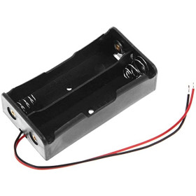
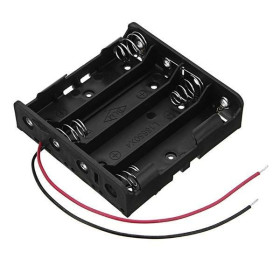
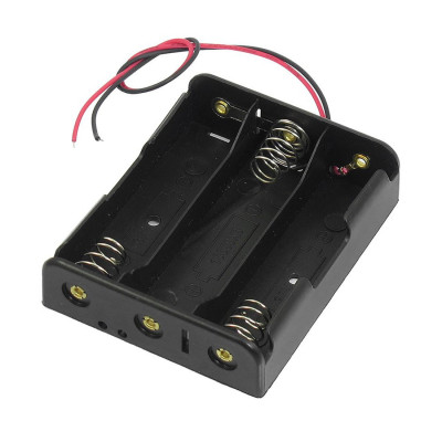
The 18650 3S battery holder is a black plastic case with three slots, which hold three 18650 Li-ion cells connected in series, and provides a portable DC voltage source. Two wires come out of it, red for positive and black for negative. It is suitable for powering DC motors, pumps, 12 V LED strips, mobile robots and buck voltage converters.
The three slots are linked together by metal strips, so the positive terminal of one cell connects to the negative terminal of the next. In this series connection the cell voltages add up, while the capacity in mAh remains that of a single cell. With three 3.7 V cells the nominal voltage is 11.1 V, which rises to 12.6 V when the cells are fully charged (3 x 4.20 V).
The main features include three slots with metal contacts, one spring contact and one flat contact, the series connection strips, the two connection wires, and the + and - signs moulded into the plastic in each slot. The pack voltage is taken directly from the red and black wires. The holder does not include a protection circuit (BMS), fuse or switch, which are added according to the load.
Specifications:
Nominal voltage: 11.1 V (3 x 3.7 V)
Fully charged pack voltage: 12.6 V (3 x 4.20 V)
Batteries: 3 x 18650 Li-ion
Cell connection: In series (3S)
Number of slots: 3
Connection wires: Red (+) and black (-)
Protection: No BMS, fuse or switch
Material: Black plastic
Dimensions: 76 x 61 x 21 mm
Layout:
| Element | Function |
|---|---|
| Battery slots | Three slots in which the 18650 cells are inserted. The + and - signs moulded into the plastic show the orientation in which each cell is placed. |
| Spring contact | Metal spring contact on which the flat end (negative) of the cell rests. |
| Flat contact | Metal contact on which the end with the raised button (positive) of the cell rests. |
| Series connection strips | Connect the positive terminal of one cell to the negative terminal of the next, so that the voltages of the three cells add up. |
| Red wire | Pack positive, 11.1 V nominal and 12.6 V at full charge. |
| Black wire | Pack negative, ground. |
Pinout:
| Connector | Pin | Function |
|---|---|---|
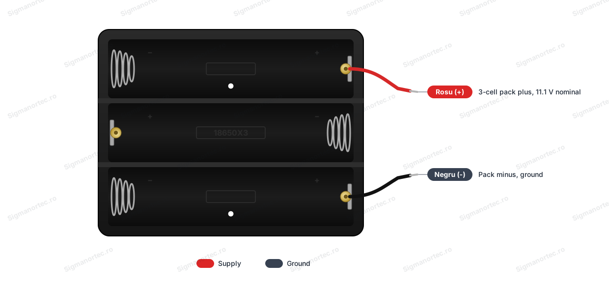
| Output wires | Red (+) | Positive of the 3-cell pack, 11.1 V nominal |
| Output wires | Black (-) | Negative of the pack, ground |
Usage:
Use three 18650 cells of the same type, with the same capacity and the same state of charge, because different cells discharge unevenly.
Insert each cell respecting the + and - signs in the slot. The flat end (negative) faces the spring contact, and the end with the raised button (positive) faces the flat contact. The cells are placed in alternating directions.
Before connecting the load, measure with a multimeter set to DC voltage between the red wire and the black wire. A value between 11 and 12.6 V shows that the assembly is correct, while a value of about 3.7 V or 7.4 V shows that a cell is inserted reversed or is not making contact.
Connect the red wire to the positive of the load and the black wire to the negative of the load, respecting the polarity.
Fit a switch in series with the red wire, so that the load is completely disconnected from the battery positive when it is off.
Check that the load accepts the range from the 11.1 V nominal up to 12.6 V. For loads of 5 V or 3.3 V, place a buck voltage converter between the holder and the load and never apply 11.1 V directly.
Protect the circuit with a fuse suited to the load current, because the holder does not limit the current and does not protect against short circuits.
Do not let the cells discharge below 2.5 - 2.8 V per cell, that is below about 7.5 - 8.4 V for the pack, and monitor the voltage with a multimeter or with a protection module.
For charging, remove the cells from the holder and use a dedicated Li-ion charger, which stops at 4.20 V per cell, or a 3S BMS module. Do not charge the cells in the holder directly from an ordinary power supply.
Remove the cells from the holder if you do not use the pack for several days.
- Dimensions
- 76 x 61 x 21 mm
- Material
- Black plastic
- Rated voltage
- 11.1 V (3 x 3.7 V)
- Protections
- No BMS, fuse or switch
- Maximum voltage
- 12.6 V (3 x 4.20 V)
- Configuration
- In series (3S)
- Battery type
- 3 x 18650 Li-ion
- Number of cells
- 3
Produs destinat utilizarii in proiecte electronice, automatizari, prototipare, educatie si cercetare.
Produsul trebuie utilizat numai conform specificatiilor tehnice mentionate in descriere si/sau in documentatia produsului.
Avertismente generale de siguranta:
Nu utilizati produsul la tensiuni, curenti sau temperaturi peste valorile specificate.
Montajul si conectarea trebuie realizate de persoane cu cunostinte tehnice minime in domeniul electric/electronic.
Evitati scurtcircuitele, inversarea polaritatii si conectarea gresita a alimentarii.
Nu lasati produsul alimentat nesupravegheat in timpul testelor.
Produsul nu este jucarie si nu este destinat copiilor.
Pentru modulele electronice, se recomanda utilizarea in carcase, panouri sau montaje protejate, dupa caz.
Identificare produs:
Denumirea produsului, codul/SKU-ul si caracteristicile tehnice sunt mentionate in pagina produsului si/sau pe eticheta ambalajului.
Producator / Importator / Distribuitor:
Sigmanortec S.R.L.
Calea Bucuresti nr. 9, Targu Jiu, Gorj, Romania
E-mail: [email protected]
Website: www.sigmanortec.ro
Persoana responsabila in UE:
Sigmanortec S.R.L.
Calea Bucuresti nr. 9, Targu Jiu, Gorj, Romania
E-mail: [email protected]
Documentatie si siguranta:
Pentru informatii suplimentare, fise tehnice, declaratii de conformitate sau instructiuni, ne puteti contacta la [email protected].
Reviews (11) - Review moderation

Perfect pentru atelier.
Produs ok,prea si calitate ok
FBFB
e ok
foarte bun
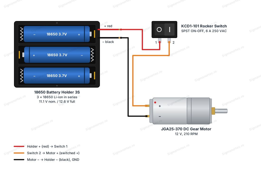
The 18650 3S battery holder is a portable power supply made of three slots connected in series, in which three 18650 Li-ion cells are inserted. The tutorial does not use any development board or any program. We put it into operation, check its voltage and use it to power a 12 V JGA25-370 geared DC motor, switched on and off with a KCD1-101 rocker switch.
Such a pack is used for motors, pumps, 12 V LED strips, mobile robots or as the input source for a buck voltage converter.

How it works:
The metal strips between the slots connect the positive terminal of one cell to the negative terminal of the next one. This is the series connection, denoted 3S. When cells are connected in series, their voltages add up, and the capacity in mAh remains that of a single cell.
An 18650 cell has a nominal voltage of 3.6 - 3.7 V, reaches 4.20 V (±0.05 V) when fully charged and should be stopped at 2.5 - 2.8 V. For three cells in series, this gives 3 x 3.7 V = 11.1 V nominal, 3 x 4.20 V = 12.6 V at full charge and approximately 7.5 - 8.4 V at the discharge limit.
The stored energy is calculated with the formula Wh = V x Ah. For example, three 2000 mAh cells give 11.1 V x 2 Ah = 22.2 Wh. The runtime is estimated with the formula time = capacity / current. A 0.15 A load theoretically draws about 13 hours from a 2 Ah pack. In practice the runtime is shorter, because the voltage drops during discharge and because the cells have losses.
The holder has no BMS, fuse or switch. Protection against short circuit, overcurrent and over-discharge must be provided by you, through a fuse, a switch and voltage monitoring.
Wiring:
Mount the switch in series with the red wire. This way, when it is off, the motor is completely disconnected from the battery positive, and the black wire goes directly to the motor negative. The terminal voltage is 11.1 V nominal and 12.6 V when the cells are full, and the 12 V JGA25-370 motor accepts this range without a converter. The contacts of the KCD1-101 switch handle 6 A, well above the motor current. The switch pins are not numbered, and the designations 1 and 2 in the table are only names used in the tutorial, so the wiring works in either direction.
| Product pin | Connect to | Role |
|---|---|---|
| Red wire (+) | Pin 1 of the KCD1-101 switch | Plus of the pack, 11.1 V nominal and 12.6 V at full charge |
| Pin 2 of the KCD1-101 switch | + terminal of the JGA25-370 motor | Switched plus to the motor |
| Black wire (-) | - terminal of the JGA25-370 motor | Common negative, ground |
If the load accepts only 5 V or 3.3 V, place a buck voltage converter between the holder and the load. Never apply 11.1 V directly to a circuit or to a 5 V or 3.3 V module.
Setup:
The holder has no buttons, potentiometers, jumpers or LEDs, so the only preparation is the correct installation of the cells. Use three 18650 cells with the same capacity, of the same type and with the same state of charge. Different or unevenly charged cells discharge unevenly, and the weakest one may drop below the voltage limit and wear out.
For each cell, follow the + and - signs molded into the plastic of the slot. The flat end (minus) goes toward the spring, and the end with the protruding button (plus) goes toward the flat contact. The cells are placed in alternating orientations, and the plastic markings show the correct direction for each slot.
Before connecting the load, measure with a multimeter set to DC voltage between the red wire and the black wire. The correct value is between 11 V and 12.6 V. If you measure about 3.7 V or 7.4 V, one or two cells are installed backwards or do not make contact. Remove the cells and check them again.
For charging, remove the cells from the holder and put them in a dedicated Li-ion charger, which stops at 4.20 V per cell. Alternatively, you can charge the pack through a 3S BMS module connected to the holder. Do not charge the cells in the holder directly from an ordinary power supply, because the holder does not limit the voltage and does not stop the charging.
Usage example:
The example powers a 12 V, 210 RPM JGA25-370 motor, switched on and off with the KCD1-101 switch. Set the switch to the off position (O) and leave the holder without cells.
Connect the wires according to the table in the Wiring section. The red wire goes to pin 1 of the switch, pin 2 goes to the + terminal of the motor, and the - terminal of the motor goes to the black wire. Check that there are no bare wires touching each other.
Insert the three cells following the + and - signs in the slots. With the switch in the off position, measure between the red wire and the black wire. You should read between 11 and 12.6 V.
Press the switch to the on position (I). The motor should start immediately and rotate freely at about 210 RPM. The no-load current is on the order of 0.04 - 0.15 A, and with the rotor locked it rises to about 1200 mA, so do not keep the motor locked for more than a few seconds.
To reverse the direction of rotation, switch off and swap the two wires at the motor. After use, set the switch to the off position. If you do not use the pack for several days, remove the cells from the holder.
Common problems:
The motor does not start and the multimeter shows 0 V. The usual cause is a weak contact between a cell and the strip or spring, or a cell installed backwards. Reinsert the cells one at a time and check the + and - signs in the slots.
The measured voltage is about 3.7 V or 7.4 V instead of 11 - 12.6 V. One or two cells are installed backwards or do not make contact. Remove the cells and measure each cell separately, the correct value being about 3.6 - 4.2 V.
The motor turns slowly or the voltage drops a lot when it starts. The cells are discharged or have high internal resistance, or the contacts are oxidized. Charge the cells, clean the contacts and replace the old cells.
The wires heat up or the switch gets hot. The load current is too high for the wires or the contacts. Reduce the load and check that the switch and fuse are rated for the real current.
The pack discharges quickly. The cells have low capacity or are worn out, and one weaker cell lowers the voltage of the whole pack. Replace the cells with three identical cells of the same capacity.
Limitations and tips:
The holder has no BMS, fuse or switch, so it does not protect the cells against short circuit, overcurrent or over-discharge. The maximum current depends on the cells used and the connecting wires, not on the holder. Never connect the red wire and the black wire to each other.
The capacity of the pack is that of a single cell, and the voltage varies between about 12.6 V at full charge and 7.5 - 8.4 V at the discharge limit, so the load must accept this range.
For a more complete pack, add a 3S BMS module and a fuse. For lower-voltage loads, add a buck voltage converter adjusted to the desired value.