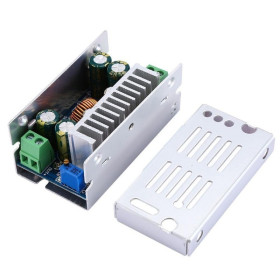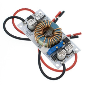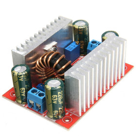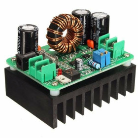

Product images are for informational purposes only and may vary slightly depending on the batch and supplier. Product specifications and prices may be subject to change without notice. We do our best to provide accurate and complete product specifications, but they may not be completely accurate. If you encounter any such situation, please let us know.
The product is intended for specialists and requires qualified and authorized personnel. The product does not include assembly/use instructions . Putting the product into operation by unqualified persons leads to the loss of the warranty according to the Terms and Conditions on the site.
The specified technical parameters (current, power, etc.) represent maximum allowable values under ideal operating conditions. For safe use and optimal lifespan, it is recommended to operate the product continuously at no more than 50% of the specified maximum values.
DC-DC Boost Step-Up Converter 150W, 10-32V to 12-35V, 6A, Adjustable
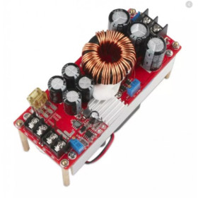
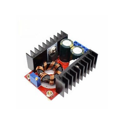
DC-DC boost step-up converter for powering 12 - 35 VDC loads from batteries or 10 - 32 VDC sources. The output voltage is continuously adjustable with a multiturn trimmer, the output current reaches 6 A, and the power reaches 100 W without cooling and 150 W with active cooling. 94% efficiency and two heatsinks included.
Buying this product earns you 1.11 RON in loyalty points.

International fast shipping within EU. Free Shipping for orders above 100 EUR in most EU countries.

We ship from our stock within 24H

You earn points with every order, worth 5%.
The DC-DC boost step-up converter, non-isolated, raises a DC input voltage of 10 - 32 VDC to an adjustable output voltage between 12 and 35 VDC, at an output current of up to 6 A. It is suitable for powering higher-voltage loads from a battery or from a 12 V or 24 V source, for example chargers and laptop power supplies in vehicles, projects with rechargeable batteries, small solar systems and laboratory equipment.
The output power is 100 W without additional cooling and 150 W with active cooling. The conversion efficiency is 94%, and the output ripple is 2%. The output voltage is continuously adjustable with a multiturn trimmer, and the output voltage must always be set above the input voltage. The module operates in the temperature range -40 to +85 degrees C and has no short-circuit or reverse-polarity protection.
The main features include the screw terminal block for input and output, the power toroidal inductor, the two electrolytic capacitors, the two heatsinks for the power components, the multiturn trimmer for adjusting the output voltage and the voltage indicator LED. The module is powered from a DC source of 10 - 32 VDC, with a maximum input current of 10 A, and above this value the cooling must be improved.
The module has no data interfaces, so it requires no programming and can be used with any DC source and any load within the indicated voltage range, including in projects built with Arduino, ESP32, STM32 or Raspberry Pi, when these have a power stage at 12 - 35 VDC in their circuit.
Specifications:
Supply voltage: 10 - 32 VDC
Input current: 10 A max, above 10 A the cooling must be improved
Output current: 6 A max
Module type: Step-up (boost), non-isolated
Output voltage: 12 - 35 VDC, adjustable
Output power: 100 W without cooling, 150 W with active cooling
Conversion efficiency: 94%
Output ripple: 2%
Voltage adjustment: Multiturn trimmer
Connections: Screw terminals (IN+, IN-, OUT+, OUT-)
Short-circuit and reverse-polarity protection: No
Operating temperature: -40 to +85 degrees C
Dimensions: 65 x 23 x 56.3 mm
Layout:
| Element | Function |
|---|---|
| Screw terminal block | Two pairs of terminals for connecting the power supply (IN+, IN-) and the load (OUT+, OUT-). |
| Red indicator LED | Lights up when the module receives input voltage. If the LED does not light up, check the source and the polarity of the connections. |
| Blue multiturn trimmer | Adjusts the output voltage between 12 and 35 VDC. Turning clockwise increases the output voltage, and counterclockwise decreases it. |
| Toroidal inductor | Power coil of the boost converter, in which the energy transferred to the output is stored. |
| Electrolytic capacitors | Filter the output voltage and limit the ripple. |
| Heatsinks | Dissipate the heat generated by the power components. At input currents above 10 A or at 150 W, active cooling with a fan is recommended. |
| Mounting holes | Fixing the board in a enclosure or on a support. |
Pinout:
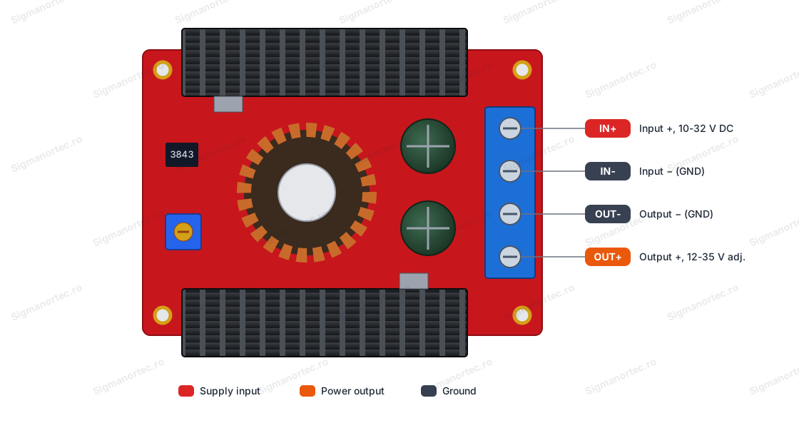
| Connector | Pin | Function |
|---|---|---|
| Input terminal block | IN+ | Power supply positive, 10 - 32 VDC |
| Input terminal block | IN- | Power supply negative (GND) |
| Output terminal block | OUT- | Load negative (GND) |
| Output terminal block | OUT+ | Load positive, 12 - 35 VDC adjustable |
Usage:
Before connecting, check that the source voltage is between 10 and 32 VDC and that the desired output voltage is higher than the input voltage, because the module works only as a voltage step-up.
Connect the power supply to the IN+ and IN- terminals, carefully observing the polarity, because the module has no reverse-polarity protection.
Install a suitable fuse in series with the power supply and, for reverse-polarity protection, a diode in series with the input, because the module has no short-circuit protection.
Do not connect the load during the first adjustment. Power the module and check that the red LED lights up.
Measure the voltage at the OUT+ and OUT- terminals with a multimeter set to DC voltage and turn the multiturn trimmer with a small screwdriver until the desired value is reached. Turning clockwise increases the output voltage, and turning counterclockwise decreases it. The trimmer has several turns, so the adjustment is made slowly, following the value shown on the multimeter.
If you do not know the initial position of the trimmer, first turn it counterclockwise for a minimum output voltage, then gradually increase the voltage.
Disconnect the power supply, connect the load to the OUT+ and OUT- terminals, then power the module again. Check the output voltage under load and correct it from the trimmer if necessary.
The IN- and OUT- terminals are electrically connected to each other on the board, so the input and output share a common ground.
Do not exceed 6 A output current and 150 W output power. Without additional cooling, limit the power to 100 W.
At input currents above 10 A or at high ambient temperatures, use a fan that blows directly on the heatsinks and keep the space around the module clear.
For stable results, use short cables with a cross-section sufficient for the input and output currents, and tighten the terminal screws well.
- Dimensions
- 65 x 23 x 56.3 mm
- Type
- Step-up (boost), non-isolated
- Output voltage
- 12-35 V DC, adjustable
- Operating temperature
- -40 la +85 grade C
- Output current
- 6 A max
- Input voltage
- 10-32 V DC
- Output power
- 100 W without cooling, 150 W with active cooling
- Efficiency
- 94%
- Input current
- 10 A max
Produs destinat utilizarii in proiecte electronice, automatizari, prototipare, educatie si cercetare.
Produsul trebuie utilizat numai conform specificatiilor tehnice mentionate in descriere si/sau in documentatia produsului.
Avertismente generale de siguranta:
Nu utilizati produsul la tensiuni, curenti sau temperaturi peste valorile specificate.
Montajul si conectarea trebuie realizate de persoane cu cunostinte tehnice minime in domeniul electric/electronic.
Evitati scurtcircuitele, inversarea polaritatii si conectarea gresita a alimentarii.
Nu lasati produsul alimentat nesupravegheat in timpul testelor.
Produsul nu este jucarie si nu este destinat copiilor.
Pentru modulele electronice, se recomanda utilizarea in carcase, panouri sau montaje protejate, dupa caz.
Identificare produs:
Denumirea produsului, codul/SKU-ul si caracteristicile tehnice sunt mentionate in pagina produsului si/sau pe eticheta ambalajului.
Producator / Importator / Distribuitor:
Sigmanortec S.R.L.
Calea Bucuresti nr. 9, Targu Jiu, Gorj, Romania
E-mail: [email protected]
Website: www.sigmanortec.ro
Persoana responsabila in UE:
Sigmanortec S.R.L.
Calea Bucuresti nr. 9, Targu Jiu, Gorj, Romania
E-mail: [email protected]
Documentatie si siguranta:
Pentru informatii suplimentare, fise tehnice, declaratii de conformitate sau instructiuni, ne puteti contacta la [email protected].
Reviews (6) - Review moderation

Foarte buna dar atentie la recomandarile de limitare a curentului maxim . De preferita utizati cu un mic vetilator alimentat la 8vrn
A functionat din prima. Atentie insa : nu alimentati cu tensiune mai mica decat cea indicata ! Eu am folosit o sursa de 12 V ,cumparata tot de la Sigmanortec .
Isi face treaba, pentru puteri mai mari eate necesara racire activa cu cooler
Bun
Produsul este ok. Este exact ca in descriere si poza. Livrarea a fost rapida. Recomand.
This tutorial uses the module itself, without a development board and without a program. The DC 150W step-up power supply is a boost converter that takes a 10 - 32 VDC input and gives an adjustable output between 12 and 35 VDC, at a maximum of 6 A. It is used when you have a voltage source lower than the one required by the load, for example a 12 V adapter for a 24 V fan, a car battery for a 19 V consumer or a battery pack for an amplifier.
How it works:
The module is a non-isolated DC-DC boost converter. A MOSFET transistor rapidly switches the current through the toroidal coil. When the transistor conducts, the coil stores energy. When it turns off, its energy adds to the input voltage and passes through the diode into the electrolytic capacitors at the output. The ratio between the conduction time and the switching period is called the duty factor D and sets the output voltage.
For an ideal boost converter, Vout = Vin / (1 - D). For Vin = 12 V and Vout = 24 V, D = 1 - 12 / 24 = 0.5. The control circuit compares the output voltage with a reference and corrects the duty factor by itself. The blue potentiometer changes this comparison, so through it you choose the output voltage.
This structure gives an important rule: the output cannot be lower than the input. Even without load, the output voltage stays at least at the level of the input voltage, because the diode connects the input to the output. If you want a voltage lower than the source, you need a step-down converter, not this module.
Power is conserved, with losses. With an efficiency of 94% (value measured at 16 V input, 19 V output and 2.5 A), the input current is Iin = Pout / (0.94 x Vin). At 35 V and 2.85 A the output is approximately 100 W, which is the limit for operation without a fan. The 150 W power is reached only with forced air over the heatsinks, and at the input the maximum current is 10 A. Without load, the module consumes approximately 25 mA.
Connection:
The example uses a 12 VDC 5 A mains adapter with a 5.5 x 2.1 mm plug, center positive, a socket-to-screw-terminal adapter and an 80 mm, 24 VDC 0.15 A fan with two wires. The module has a single 4-way blue terminal block, in the order IN+, IN-, OUT-, OUT+. Check the markings on the board before making the connections. There is no reverse polarity protection and no short-circuit protection, so a wiring mistake will damage the module. A fuse on the wire going to IN+, sized for the power supply current, is recommended.
| Product pin | Connect to | Role |
|---|---|---|
| IN+ | The + terminal of the socket adapter, i.e. the positive of the 12 VDC adapter | Input power, 10 - 32 VDC |
| IN- | The - terminal of the socket adapter, i.e. the negative of the 12 VDC adapter | Input ground |
| OUT+ | The positive wire of the 24 VDC fan | Adjustable output, 12 - 35 VDC |
| OUT- | The negative wire of the 24 VDC fan | Output ground |
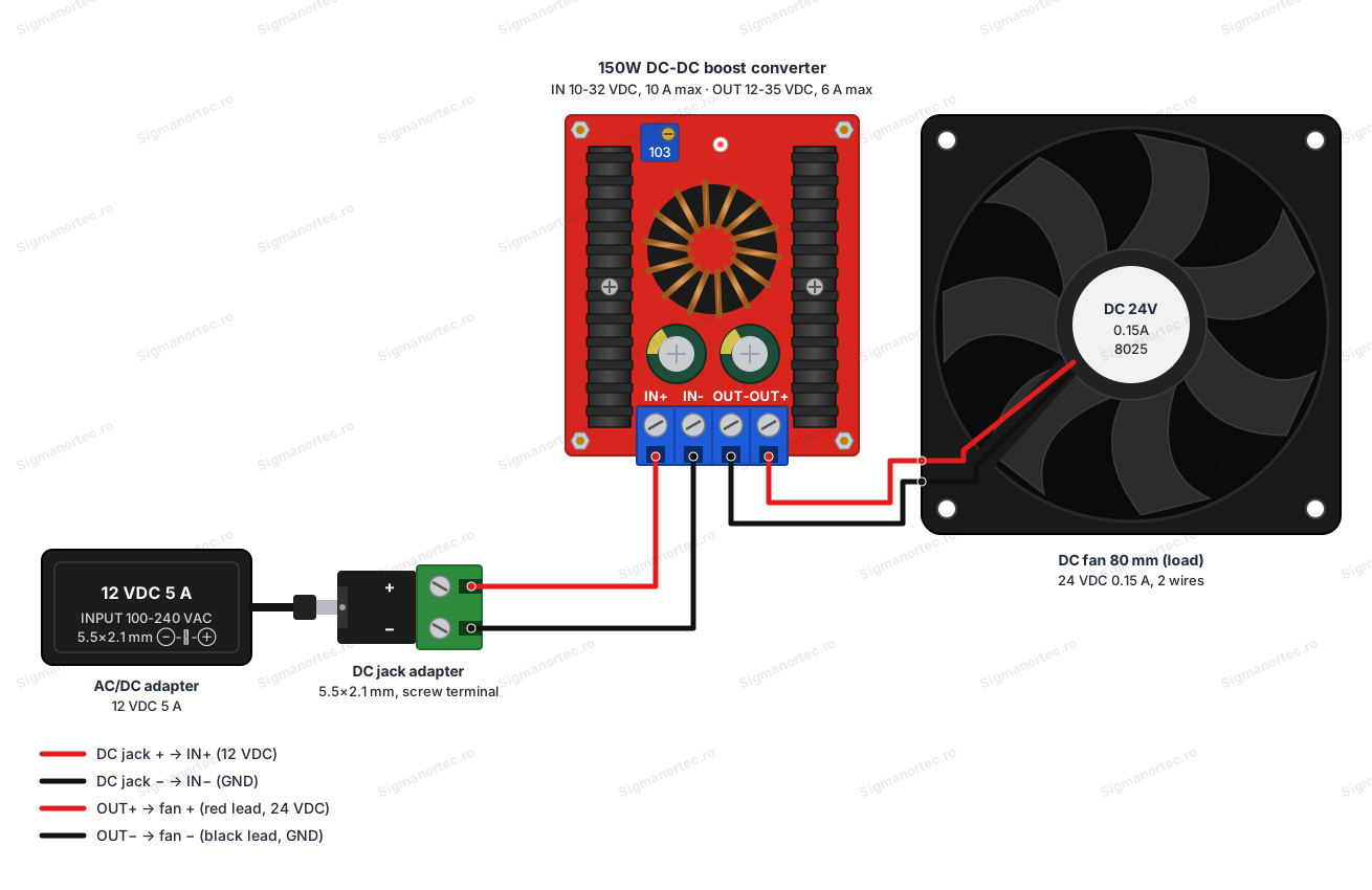
The input and output share a common ground inside the module, because the converter is not isolated. Do not connect together the two grounds of different power sources without making sure that no equalization currents appear.
Buttons, adjustments and indicators:
| Element | What it does | How to use it |
|---|---|---|
| Blue multi-turn potentiometer, marked 103 | Sets the output voltage, between 12 and 35 VDC | Turned clockwise it increases the output voltage, turned counterclockwise it decreases it. It is adjusted with a multimeter connected to OUT+ and OUT-, without load |
| 4-way blue terminal block | The input and output of the module | The order is IN+, IN-, OUT-, OUT+. Tighten the wires with a small screwdriver, after checking the polarity |
| Black heatsinks (2 pcs) | Dissipate the heat from the MOSFET transistor and the diode | Not adjustable. Keep the air free around them and add a fan when the power exceeds 100 W |
| Power LED | Lights up when the module is powered, on the board variants that have it | If the LED lights up, the input voltage reaches the module. When it is missing, use the multimeter |
| Buttons, jumpers, switches, display | The module has no such elements | The only adjustment is the potentiometer |
Adjusting the output voltage takes a few steps. Disconnect the load from OUT+ and OUT-. Connect the multimeter, set to DC voltage, to OUT+ and OUT-. Power the module and read the value. Turn the potentiometer with a small screwdriver, clockwise to increase the voltage and counterclockwise to decrease it. The potentiometer has several turns, so the voltage changes gradually and you need to turn it several times. Stop when the multimeter shows the desired value.
The adjustment is mechanical, so the value stays set after you cut the power. There is no factory-guaranteed starting position, so always measure the output before connecting the load.
Configuration:
The module has no menus and does not store electronic settings. The only parameter to set is the output voltage, and the limits depend on the input voltage, which must stay between 10 and 32 VDC. To have a stable output, choose an output voltage at least 2 - 3 V higher than the input. The output can be adjusted between 12 and 35 VDC.
| Parameter | Value | Note |
|---|---|---|
| Input voltage | 10 - 32 VDC | Applied to IN+ and IN-, with the correct polarity |
| Output voltage | 12 - 35 VDC | Set with the potentiometer, must be higher than the input |
| Input current | 10 A maximum | Above 10 A, improve the cooling |
| Output current | 6 A maximum | Limit the current so that the power does not exceed the permitted value |
| Output power | 100 W without cooling, 150 W with forced air | At 35 V the current is limited to approximately 2.85 A without a fan |
Usage example:
The example powers an 80 mm, 24 VDC 0.15 A fan from a 12 VDC 5 A adapter. Check that the adapter plug has the center positive, then insert it into the socket-to-screw-terminal adapter. Connect the + terminal to IN+ and the - terminal to IN-. Do not connect the fan yet.
Connect the adapter to the mains with the module connected to the input, and place the multimeter on OUT+ and OUT-. The initial reading may differ from 24 V. Turn the potentiometer clockwise if the value is too low, or counterclockwise if it is too high, until the multimeter shows 24.0 V.
Disconnect the adapter from the socket, remove the multimeter and connect the fan: the positive wire to OUT+ and the negative wire to OUT-. Power on again. The fan starts and consumes approximately 3.6 W (24 V x 0.15 A). About 0.32 A is drawn from the 12 V adapter, slightly more at light load, where the efficiency is below the value measured at 2.5 A. Measure the voltage again with the fan connected. If it drops a lot, the adapter or the wires are undersized.
Common problems:
The module gives no output voltage and the LED, if present, does not light up. The usual cause is reversed polarity or a loose connection in the terminal block. Check with the multimeter that there is source voltage between IN+ and IN-, with the negative on IN-, and tighten the screw well.
The output does not drop below the input voltage. This is the normal behavior of a boost converter, because the diode connects the input to the output. For a lower voltage, use another type of converter.
The output voltage is unstable or drops when you connect the load. The adapter cannot supply the requested current or the wires are too thin. Calculate the input current with the formula Iin = Pout / (0.94 x Vin) and choose a power supply and cables for this current, with a margin.
The heatsinks get very hot. At powers close to 100 W it is normal for them to heat up. Above this value, add a fan that blows over the heatsinks. Do not touch the heatsinks during operation.
The load received too high a voltage. The potentiometer was turned after the load was connected, or the voltage was not checked. Always adjust without load and measure with the multimeter before connecting the consumer.
The module failed because of a short circuit on the output. It has no short-circuit protection, so a fuse on the input and checking the wiring are mandatory.
Limitations and tips:
The module is non-isolated, so it does not galvanically separate the load from the source. It has no reverse polarity protection, no short-circuit protection, and no adjustable current limiting. The 94% efficiency is the value at 16 V input, 19 V output and 2.5 A, and the output ripple is approximately 2%. The operating temperature range is from -40 to +85 degrees C.
For low noise, keep the wires short and use conductors with a cross-section suited to the current. If you power sensitive equipment, add an extra capacitor or a filter at the output. The module suits 19 V laptops powered from a 12 V battery, fans, small motors, audio amplifiers or LED lamps that need a higher voltage than the one available. For a more flexible laboratory power supply, you can add a panel voltmeter at the output, and for safety a fuse at the input.