

Product images are for informational purposes only and may vary slightly depending on the batch and supplier. Product specifications and prices may be subject to change without notice. We do our best to provide accurate and complete product specifications, but they may not be completely accurate. If you encounter any such situation, please let us know.
The product is intended for specialists and requires qualified and authorized personnel. The product does not include assembly/use instructions . Putting the product into operation by unqualified persons leads to the loss of the warranty according to the Terms and Conditions on the site.
The specified technical parameters (current, power, etc.) represent maximum allowable values under ideal operating conditions. For safe use and optimal lifespan, it is recommended to operate the product continuously at no more than 50% of the specified maximum values.
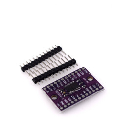
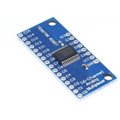
16-channel multiplexer module
Quickly expands the number of inputs or outputs of the microcontroller, allowing reading or switching of up to 16 channels through a single signal pin. Based on the CD74HC4067, it supports analog and digital signals, operates at 3-6V and is compatible with Arduino and other development boards. Channel selection is simple via 4 address pins, and the EN pin allows quick activation or deactivation.
Buying this product earns you 0.24 RON in loyalty points.

International fast shipping within EU. Free Shipping for orders above 100 EUR in most EU countries.

We ship from our stock within 24H

You earn points with every order, worth 5%.
16CH multiplexer module, CD74HC4067, for reading up to 16 channels on a single signal line, compatible with Arduino and other development boards. The module works with both Analog and Digital signals.
This efficient solution helps you save valuable pins on the microcontroller, making it ideal for applications with many inputs/outputs, without compromising performance or flexibility.
This breakout board is built around the CD74HC4067 chip, a versatile 16-channel multiplexer/demultiplexer, ideal for extending the number of analog and digital inputs or outputs available on a microcontroller. Acting as an internal rotary switch, the chip allows connecting the common pin (SIG) to any of the 16 channels (CHAN00–CHAN15), based on a binary signal sent through the selection pins (S0–S3). The board supports both digital and analog signals (voltage between GND and VCC) and allows bidirectional communication.
Thanks to this functionality, the board is perfect for projects involving sensor multiplexing, switching serial communication lines (e.g., TTL), or even interfacing with protocols like I2C or SPI by adding multiple boards. Additionally, the enable pin (EN) output allows complete deactivation of the connection between the common pin and individual channels, offering advanced control over signal traffic.
Allows "break-before-make" switching to reduce interference.
Specifications:
Supply voltage: 3 - 6VDC
Chip: CD74HC4067
Number of channels: 16 (CHAN00 – CHAN15)
Compatible with signals: Digital and analog
Operating voltage: between GND and VCC
Channel selection control: digital pins S0 – S3 (binary addressing)
Enable pin (EN): breaks all connections when set HIGH
Connections:
| CD74HC4067 Pin | Function | Connected to Arduino Uno |
|---|---|---|
| VCC | Power supply +5V or +3.3V | 5V |
| GND | Ground | GND |
| SIG | Common signal (analog/digital I/O) | A0 (or other analog pin) |
| S0 | Address selection - bit 0 | D4 |
| S1 | Address selection - bit 1 | D5 |
| S2 | Address selection - bit 2 | D6 |
| S3 | Address selection - bit 3 | D7 |
| EN (Enable) | Chip enable (LOW = active) | GND (or a digital pin if control is desired) |
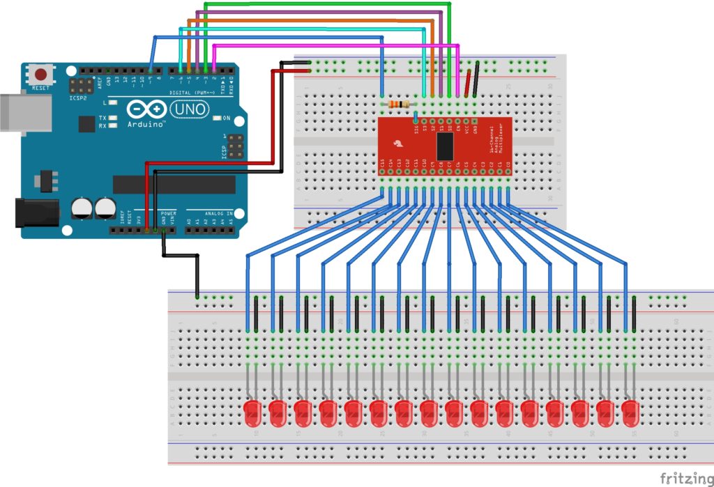
Usage:
Connect the SIG pin to the common line of the system (for example, an analog or digital input of the microcontroller).
Connect the S0–S3 pins to the digital outputs of the microcontroller and send the binary address of the desired channel.
Connect external devices or sensors to the CHAN00–CHAN15 pins.
(Optional) Use the EN pin to completely disable switching when needed.
Channel selection is done in binary mode via the selection pins S0, S1, S2, S3, where S0 is the LSB (least significant bit) and S3 is the MSB (most significant bit). Below is the addressing table for all channels:
| Channel | S3 | S2 | S1 | S0 | Binary value |
|---|---|---|---|---|---|
| CH0 | 0 | 0 | 0 | 0 | 0000 |
| CH1 | 0 | 0 | 0 | 1 | 0001 |
| CH2 | 0 | 0 | 1 | 0 | 0010 |
| CH3 | 0 | 0 | 1 | 1 | 0011 |
| CH4 | 0 | 1 | 0 | 0 | 0100 |
| CH5 | 0 | 1 | 0 | 1 | 0101 |
| CH6 | 0 | 1 | 1 | 0 | 0110 |
| CH7 | 0 | 1 | 1 | 1 | 0111 |
| CH8 | 1 | 0 | 0 | 0 | 1000 |
| CH9 | 1 | 0 | 0 | 1 | 1001 |
| CH10 | 1 | 0 | 1 | 0 | 1010 |
| CH11 | 1 | 0 | 1 | 1 | 1011 |
| CH12 | 1 | 1 | 0 | 0 | 1100 |
| CH13 | 1 | 1 | 0 | 1 | 1101 |
| CH14 | 1 | 1 | 1 | 0 | 1110 |
| CH15 | 1 | 1 | 1 | 1 | 1111 |
Recommendations:
Add a 100nF capacitor between VCC and GND, as close as possible to the chip, to reduce electrical noise.
Make sure that the input signal voltages do not exceed VCC (usually 5V or 3.3V).
For reading buttons or other digital signals, configure the SIG pin as INPUT_PULLUP and interpret the read values as HIGH or LOW.
Produs destinat utilizarii in proiecte electronice, automatizari, prototipare, educatie si cercetare.
Produsul trebuie utilizat numai conform specificatiilor tehnice mentionate in descriere si/sau in documentatia produsului.
Avertismente generale de siguranta:
Nu utilizati produsul la tensiuni, curenti sau temperaturi peste valorile specificate.
Montajul si conectarea trebuie realizate de persoane cu cunostinte tehnice minime in domeniul electric/electronic.
Evitati scurtcircuitele, inversarea polaritatii si conectarea gresita a alimentarii.
Nu lasati produsul alimentat nesupravegheat in timpul testelor.
Produsul nu este jucarie si nu este destinat copiilor.
Pentru modulele electronice, se recomanda utilizarea in carcase, panouri sau montaje protejate, dupa caz.
Identificare produs:
Denumirea produsului, codul/SKU-ul si caracteristicile tehnice sunt mentionate in pagina produsului si/sau pe eticheta ambalajului.
Producator / Importator / Distribuitor:
Sigmanortec S.R.L.
Calea Bucuresti nr. 9, Targu Jiu, Gorj, Romania
E-mail: [email protected]
Website: www.sigmanortec.ro
Persoana responsabila in UE:
Sigmanortec S.R.L.
Calea Bucuresti nr. 9, Targu Jiu, Gorj, Romania
E-mail: [email protected]
Documentatie si siguranta:
Pentru informatii suplimentare, fise tehnice, declaratii de conformitate sau instructiuni, ne puteti contacta la [email protected].
Reviews (5) - Review moderation

Salut, vreau sa am 10 input-uri de 0-10v si un output de valoarea cea mai mare dintre ele tot in 0-10v. pot realiza asta cu acest modula imi trebuie o sursa de 2vdca
Ok
Raport pret calitate excelent.
Recomand
Ma gandesc sa fac un secventiator cu el si e gata construit.