
Product images are for informational purposes only and may vary slightly depending on the batch and supplier. Product specifications and prices may be subject to change without notice. We do our best to provide accurate and complete product specifications, but they may not be completely accurate. If you encounter any such situation, please let us know.
The product is intended for specialists and requires qualified and authorized personnel. The product does not include assembly/use instructions . Putting the product into operation by unqualified persons leads to the loss of the warranty according to the Terms and Conditions on the site.
The specified technical parameters (current, power, etc.) represent maximum allowable values under ideal operating conditions. For safe use and optimal lifespan, it is recommended to operate the product continuously at no more than 50% of the specified maximum values.
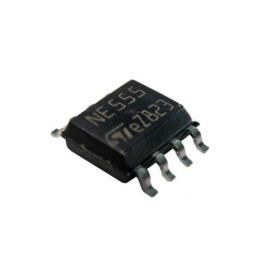
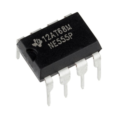
Timer IC NE555P, DIP-8, 4.5-16V, 200mA output
Integrated circuit for quickly building timers, oscillators and pulse generators in electronic projects. It works in monostable and astable modes, offers good timing stability, low consumption and an output able to directly drive light loads, ideal for prototypes, simple automation and educational applications.
Buying this product earns you 0.06 RON in loyalty points.

International fast shipping within EU. Free Shipping for orders above 100 EUR in most EU countries.

We ship from our stock within 24H

You earn points with every order, worth 5%.
The NE555P integrated circuit is a precision timer in a DIP-8 package, which generates exact delays or oscillations with the help of two or three external passive components. It can work as a monostable, with a single pulse at the output, or as an astable, as a continuous oscillator, making it suitable for flashing LEDs, power-on or power-off delays, tone generators, simple PWM control, switch debouncing and drivers for relays or small loads.
Inside there is a divider made of three equal 5 kohm resistors, which creates two thresholds: 1/3 of VCC for the TRIG input and 2/3 of VCC for the THRES input. Two comparators compare the voltage on these inputs with the thresholds and control a flip-flop, which sets the OUT output high or low and controls an internal transistor that connects the DISCH pin to ground. Times and frequencies are set by the values of the resistors and the external capacitor, from 10 us up to hours, and from below 1 mHz up to 100 kHz respectively. The thresholds are proportional to VCC, as is the charging speed of the capacitor, so the timing does not depend on the supply voltage as long as it remains constant.
Main features include the DIP-8 package for breadboards and through-hole PCBs, the OUT output that can source or sink up to 200 mA, the active-low RESET pin, the CONT pin for modifying the thresholds, and the TTL-compatible output at a 5 V supply. The supply voltage is 4.5 - 16 VDC, and the operating temperature range is 0 - 70 °C.
Specifications:
Supply voltage: 4.5 - 16 VDC
Supply current (output low, no load): 3 mA at 5 V, 10 mA at 15 V
OUT output current: up to 200 mA sourced or sunk
Type: Precision timer, monostable and astable
TRIG threshold: 1/3 VCC
THRES threshold: 2/3 VCC
Timing range: from 10 us up to hours
Frequency range: from below 1 mHz up to 100 kHz
Output level: TTL compatible at a 5 V supply
Operating temperature: 0 - 70 °C
Package: DIP-8 (PDIP)
Dimensions: 9.81 x 6.35 mm
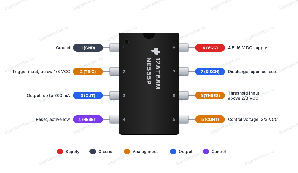
Pinout:
| Connector | Pin | Function |
|---|---|---|
| DIP-8 package | 1 (GND) | Ground. |
| DIP-8 package | 2 (TRIG) | Trigger input. When the voltage drops below 1/3 VCC, the output goes high and the discharge is blocked. |
| DIP-8 package | 3 (OUT) | Circuit output, with current up to 200 mA. |
| DIP-8 package | 4 (RESET) | Active-low reset. When pulled to ground, the output and discharge go low. Connect to VCC when not used. |
| DIP-8 package | 5 (CONT) | Access to the 2/3 VCC threshold of the comparators. Usually connected to ground through a 10 nF ceramic capacitor. |
| DIP-8 package | 6 (THRES) | Timing end input. When the voltage exceeds 2/3 VCC, the output goes low. |
| DIP-8 package | 7 (DISCH) | Open-collector output, for discharging the timing capacitor. |
| DIP-8 package | 8 (VCC) | Supply 4.5 - 16 VDC. |
| RESET (pin 4) | TRIG (pin 2) | THRES (pin 6) | OUT (pin 3) | DISCH (pin 7) |
|---|---|---|---|---|
| Low | Any | Any | Low | Conducts to ground |
| High | Below 1/3 VCC | Any | High | Blocked |
| High | Above 1/3 VCC | Above 2/3 VCC | Low | Conducts to ground |
| High | Above 1/3 VCC | Below 2/3 VCC | Previous state | Previous state |
Usage:
Place the chip on the breadboard with the notch facing left. Pin 1 is the first pin at the bottom left, looking at the chip from above, and the numbering goes counterclockwise, so pin 8 is at the top left.
Power the circuit with a voltage between 4.5 and 16 VDC and respect the polarity. Do not apply more than 16 V and do not apply input voltages higher than VCC to the input pins.
For monostable operation, connect resistor R between VCC and pins 6 and 7 tied together, mount capacitor C between these pins and ground, and connect TRIG to VCC through a 10 kohm resistor and to ground through a push button. The pulse duration is t = 1.1 x R x C, for example 1.1 s for R = 100 kohm and C = 10 uF.
For astable operation, connect RA between VCC and pin 7, RB between pin 7 and pins 6 and 2 tied together, and capacitor C between pins 6 and 2 and ground. The frequency is f = 1.44 / ((RA + 2 x RB) x C), the time with the output high is tH = 0.693 x (RA + RB) x C, and the time with the output low is tL = 0.693 x RB x C.
Connect pin 4 (RESET) to VCC for normal operation and mount a 10 nF ceramic capacitor between pin 5 (CONT) and ground for threshold stability.
Connect an LED with a 220 ohm series resistor to the OUT output, and the LED will blink at the calculated frequency. For inductive loads, such as a relay coil, mount a diode in parallel with the coil.
If you use a supply higher than 5 V, the output rises close to VCC, so do not connect it directly to a 3.3 V logic input.
For stable results, use a constant power supply during the interval, short conductors and good quality capacitors, and for precise timing choose resistors with low tolerance.
- Supply voltage
- 4.5-16 V DC
- Dimensions
- 9.81 x 6.35 mm
- Type
- Precision timer, monostable and astable
- Operating temperature
- 0-70 °C
- Output current
- pana la 200 mA
- Operating frequency
- sub 1 MHz - 100 kHz
- Power consumption
- 3 mA la 5 V, 10 mA la 15 V
- Package
- DIP-8 (PDIP)
Produs destinat utilizarii in proiecte electronice, automatizari, prototipare, educatie si cercetare.
Produsul trebuie utilizat numai conform specificatiilor tehnice mentionate in descriere si/sau in documentatia produsului.
Avertismente generale de siguranta:
Nu utilizati produsul la tensiuni, curenti sau temperaturi peste valorile specificate.
Montajul si conectarea trebuie realizate de persoane cu cunostinte tehnice minime in domeniul electric/electronic.
Evitati scurtcircuitele, inversarea polaritatii si conectarea gresita a alimentarii.
Nu lasati produsul alimentat nesupravegheat in timpul testelor.
Produsul nu este jucarie si nu este destinat copiilor.
Pentru modulele electronice, se recomanda utilizarea in carcase, panouri sau montaje protejate, dupa caz.
Identificare produs:
Denumirea produsului, codul/SKU-ul si caracteristicile tehnice sunt mentionate in pagina produsului si/sau pe eticheta ambalajului.
Producator / Importator / Distribuitor:
Sigmanortec S.R.L.
Calea Bucuresti nr. 9, Targu Jiu, Gorj, Romania
E-mail: [email protected]
Website: www.sigmanortec.ro
Persoana responsabila in UE:
Sigmanortec S.R.L.
Calea Bucuresti nr. 9, Targu Jiu, Gorj, Romania
E-mail: [email protected]
Documentatie si siguranta:
Pentru informatii suplimentare, fise tehnice, declaratii de conformitate sau instructiuni, ne puteti contacta la [email protected].
Reviews (7) - Review moderation

Deja comand de un an de zile, ii recomand oricand! Sunt pe primul loc la comandat piese. Si sunt ai profi!
Ok
Recomand
Produs bun
bun
This tutorial shows how to use the NE555P integrated circuit as an independent timer, without a development board and without a program. The circuit works on its own, powered at 5 VDC, and in the example we use it as an astable oscillator that makes an LED blink about once per second.
The NE555P is used in projects for flashing LEDs, delays at power-on or power-off, tone generators, simple PWM control and debouncing. The times and frequencies are set exclusively by the values of the resistors and the capacitor connected to it.

How it works:
Inside the NE555P there is a divider made of three equal 5 kohm resistors, which creates two thresholds: 1/3 of the supply voltage VCC for the TRIG input and 2/3 of VCC for the THRES input. Two comparators compare the voltage on these inputs with the thresholds and control a flip-flop. The flip-flop sets the OUT output to high or low level and controls an internal transistor, which connects the DISCH pin to ground.
When TRIG drops below 1/3 of VCC, the output goes high and the discharge transistor turns off, so the external capacitor starts charging through the resistor. When THRES exceeds 2/3 of VCC, the output goes low and the transistor discharges the capacitor. The thresholds are proportional to VCC, and so is the charging speed, which is why the time does not depend on the supply voltage as long as it stays constant during the interval.
In monostable mode, a short pulse on TRIG produces a single pulse at the output, with a duration of t = 1.1 x R x C. For example, for R = 100 kohm and C = 10 uF we get t = 1.1 x 100000 x 0.00001 = 1.1 s.
In astable mode, the circuit oscillates continuously, with two resistors RA and RB and a capacitor C. The frequency is f = 1.44 / ((RA + 2 x RB) x C), the time with the output high is tH = 0.693 x (RA + RB) x C, and the time with the output low is tL = 0.693 x RB x C. For RA = 1 kohm, RB = 68 kohm and C = 10 uF we get tH = 0.478 s, tL = 0.471 s and f = 1.05 Hz.
The table below shows the logic states of the circuit.
| RESET (pin 4) | TRIG (pin 2) | THRES (pin 6) | OUT (pin 3) | Discharge (pin 7) |
|---|---|---|---|---|
| Low | Any | Any | Low | Conducts to ground |
| High | Below 1/3 VCC | Any | High | Blocked |
| High | Above 1/3 VCC | Above 2/3 VCC | Low | Conducts to ground |
| High | Above 1/3 VCC | Below 2/3 VCC | Previous state | Previous state |
Connection:
The table describes the astable circuit used in the usage example, powered at 5 VDC from a 5 VDC 1 A mains adapter, through the DC jack adapter with screw terminals. The chip is placed on the breadboard with the notch facing left, and pin 1 is the first pin at the bottom left, looking at the chip from above. Numbering goes counterclockwise, so pin 8 is at the top left. Mount the electrolytic capacitor C1 with the negative (stripe) to ground and the positive to pins 2 and 6, and the ceramic capacitor C2 is marked 103 (10 nF).
| Product pin | Connect to | Role |
|---|---|---|
| Pin 1 (GND) | Power supply negative and negative of capacitor C1 | Circuit ground. |
| Pin 2 (TRIG) | Pin 6 and positive terminal of the 10 uF capacitor C1 | Triggers charging when the voltage drops below 1/3 VCC. |
| Pin 3 (OUT) | 220 ohm resistor R3, then the LED anode | Circuit output. The LED cathode goes to ground. |
| Pin 4 (RESET) | +5 V | Stays high for normal operation. |
| Pin 5 (CONT) | 10 nF ceramic capacitor C2 to ground | Stabilizes the internal thresholds. |
| Pin 6 (THRES) | Pin 2, 68 kohm RB and positive terminal of C1 | Stops charging when the voltage exceeds 2/3 VCC. |
| Pin 7 (DISCH) | Junction between 1 kohm RA and 68 kohm RB | Discharges capacitor C1 through RB. |
| Pin 8 (VCC) | +5 V and one end of RA | Circuit power supply. |
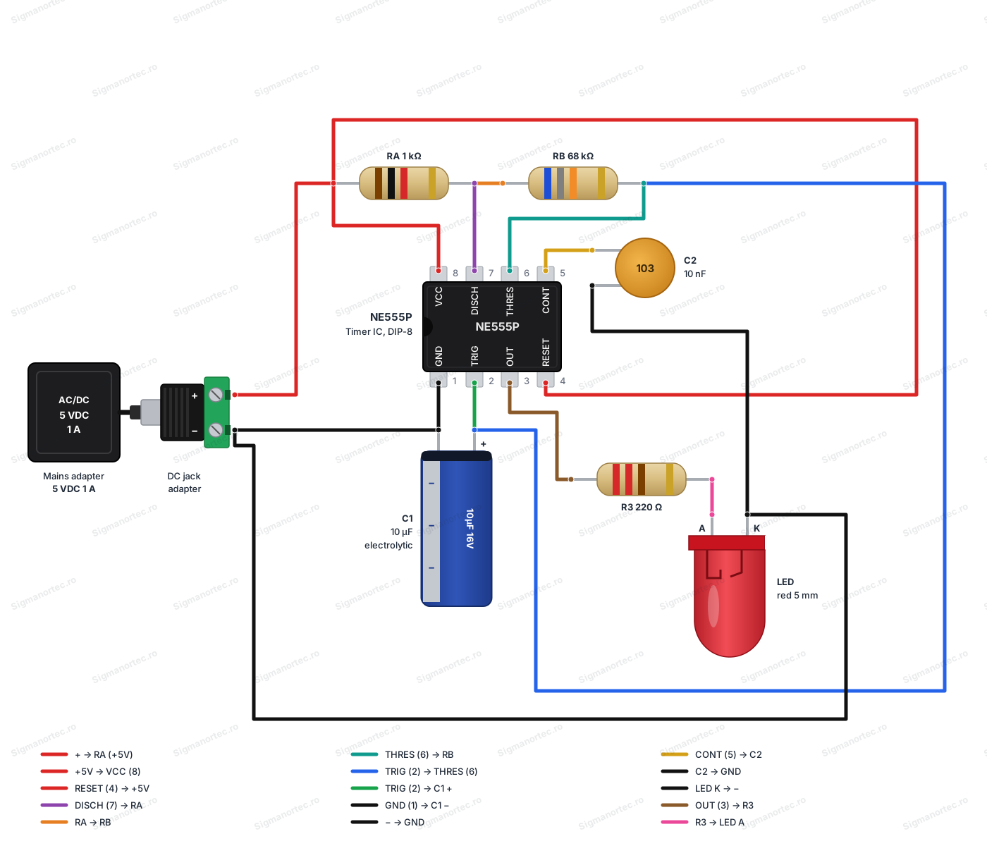
Power the circuit at a voltage between 4.5 V and 16 V and respect the polarity. With a 5 V supply the output is compatible with TTL inputs. At higher voltages the output rises close to VCC, so do not connect it directly to a 3.3 V logic input. The output can source or sink up to 200 mA. For inductive loads, for example a relay coil, mount a diode in parallel with the coil. In our example, the 220 ohm resistor limits the LED current to about 10 mA, which is safe for a 5 mm LED.
Configuration:
The NE555P has no buttons, jumpers, potentiometers or memory. The operating mode and the times are set exclusively by how the pins are connected and by the values of the external components. At every power-up the circuit restarts the cycle from the beginning, so there are no settings to save.
| Mode | Wiring | Formula |
|---|---|---|
| Monostable | R between VCC and pins 6 and 7 connected together, C between these pins and ground, TRIG to VCC through a 10 kohm resistor and to ground through a button | t = 1.1 x R x C |
| Astable | RA between VCC and pin 7, RB between pin 7 and pins 6 and 2 connected together, C between pins 6 and 2 and ground | f = 1.44 / ((RA + 2 x RB) x C) |
For monostable mode, connect pins 6 and 7 together and choose R and C for the desired duration. A short press of the button pulls TRIG below 1/3 VCC, the output goes high and stays that way for the time t. The pulse on TRIG must be shorter than the time t, otherwise the output stays high as long as the button is pressed.
For astable mode, first choose C, then RB for the time tL and RA for the difference between tH and tL. Because tH is always greater than tL, the duty cycle cannot go below 50 percent with the basic circuit. If you want a different ratio, mount a diode in parallel with RB, with the cathode toward pin 6. In this case tH depends only on RA and C, and tL depends only on RB and C.
The RESET pin (pin 4) stops the timing when pulled to ground and puts the output low. When you do not use it, connect it to VCC.
Usage example:
The example builds an LED that blinks about once per second. Mount the circuit from the connection table on a breadboard, with RA = 1 kohm, RB = 68 kohm, C1 = 10 uF electrolytic, a 10 nF capacitor on pin 5, a 5 mm red LED with a 220 ohm series resistor and a 5 V power supply.
The calculation gives tH = 0.693 x 69 kohm x 10 uF = 0.478 s and tL = 0.693 x 68 kohm x 10 uF = 0.471 s. The period is about 0.95 s, so the frequency is about 1.05 Hz.
After connecting the mains adapter to the screw terminals of the jack adapter, check the polarity of the supply and the position of capacitor C1 before powering up. Then power the assembly. The LED should light for about half a second and turn off for about half a second, repeatedly. If you want a slower rhythm, increase C1 or RB, and for a faster one decrease them, recalculating with the formulas above.
Common problems:
The LED does not blink and stays off. The most likely cause is pin 4 (RESET) left unconnected or connected to ground, which keeps the output low. Connect pin 4 to +5 V. Also check that pin 8 receives power.
The LED stays on without blinking. Pins 2 and 6 are not connected together or capacitor C1 is not connected correctly. Check the connections and the capacitor polarity, with the negative to ground.
The circuit does not work at all or gets hot. The chip is probably rotated and the pins are numbered wrongly. Turn off the power, check the position of the notch and the pin numbering, and rebuild the circuit.
The frequency differs from the calculated one. Electrolytic capacitors and resistors have tolerance, so the real values may differ. Measure the components or adjust the value of RB until you get the desired rhythm.
A relay driven by the output behaves erratically. The coil produces voltage spikes when it is switched off. Mount a diode in parallel with the coil and power the relay from a source sufficient for its current.
Limitations and tips:
The NE555P operates from 4.5 - 16 V and at temperatures between 0 and 70 °C. The output can source or sink up to 200 mA, so for larger loads use a transistor or a relay. For frequencies above 100 kHz the signal shape degrades, and for such applications a CMOS version is recommended.
Timing accuracy depends mainly on the tolerance of the resistors and the capacitor, so use low-tolerance components for precise timings. Electrolytic capacitors have leakage and high tolerance, so for very long or stable times choose other capacitor types.
With the same basic circuit you can further build a tone generator with a small speaker, a timer for lighting or a debouncer for a button, changing only the values of the resistors and the capacitor.