Product images are for informational purposes only and may vary slightly depending on the batch and supplier. Product specifications and prices may be subject to change without notice. We do our best to provide accurate and complete product specifications, but they may not be completely accurate. If you encounter any such situation, please let us know.
The product is intended for specialists and requires qualified and authorized personnel. The product does not include assembly/use instructions . Putting the product into operation by unqualified persons leads to the loss of the warranty according to the Terms and Conditions on the site.
The specified technical parameters (current, power, etc.) represent maximum allowable values under ideal operating conditions. For safe use and optimal lifespan, it is recommended to operate the product continuously at no more than 50% of the specified maximum values.
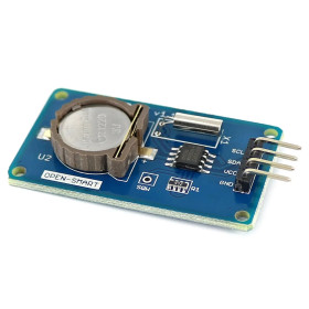
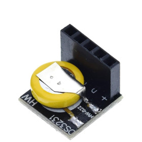
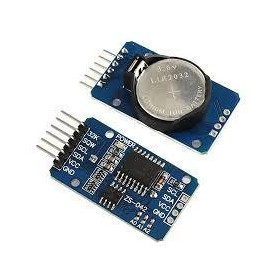
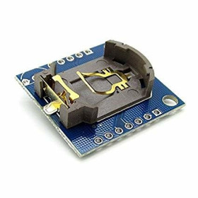
RTC Clock Module PCF8563, I2C Interface, 1.0-5.5V, Alarm and Timer, Coin Cell Holder
Keeps time and date with low power consumption, ideal for Arduino, Raspberry Pi and automation projects. The PCF8563 offers simple I2C communication, 3.3V or 5V power supply with backup battery, good stability compared to classic DS1307 modules, compact dimensions for easy integration into projects.
Buying this product earns you 0.29 RON in loyalty points.

International fast shipping within EU. Free Shipping for orders above 100 EUR in most EU countries.

We ship from our stock within 24H

You earn points with every order, worth 5%.
The RTC clock module with the PCF8563 circuit keeps the time and date in real time and retains them even when the main power supply is missing, as long as a coin cell battery is installed in the holder. It provides seconds, minutes, hours, day, weekday, month and year, and the data is read through the I2C interface. It is suitable for timestamped data logging, alarms, digital clocks, scheduled automations and any project that needs to know the exact time after a restart.
The PCF8563 is a low-power CMOS real-time clock calendar that uses a 32.768 kHz crystal and a frequency divider to generate the 1 Hz time base. Besides the clock and calendar, the circuit has an alarm, a timer, a low-voltage detector with VL indicator and a programmable clock output, with the frequencies 32.768 kHz, 1.024 kHz, 32 Hz or 1 Hz. The I2C interface supports a frequency of up to 400 kHz, and the 7-bit address is 0x51.
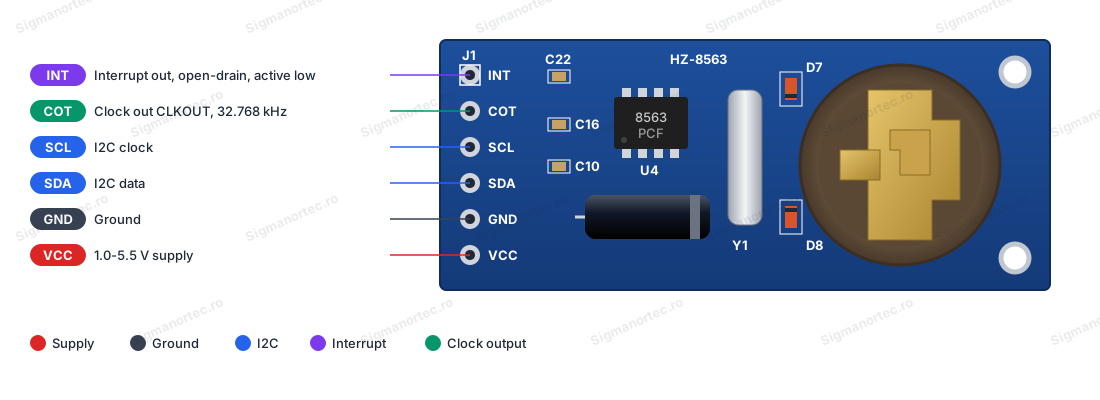
Among the main features are the PCF8563 circuit in SO8 package (U4), the 32.768 kHz crystal (Y1), the coin cell battery holder, two diodes and filter capacitors mounted on the board, two mounting holes and the J1 connector with 6 pins marked INT, COT, SCL, SDA, GND and VCC. The power supply is provided through the VCC pin at 1.0 - 5.5 V, and if the power is lost the clock keeps running from the battery installed in the holder.
Through the I2C interface, the module is compatible with Arduino, ESP32, ESP8266, STM32, Raspberry Pi and other platforms that have an I2C bus, using only two data wires, the power supply and ground.
Specifications:
Supply voltage: 1.0 - 5.5 VDC
Backup mode current: 0.25 µA typical (at 3.0 V and 25 °C)
Clock circuit: PCF8563 (SO8)
Interface: I2C
I2C address: 0x51 (7-bit)
Maximum I2C frequency: 400 kHz (at a supply of minimum 1.8 V)
Crystal: 32.768 kHz (Y1)
Data provided: Seconds, minutes, hours, day, weekday, month, year, century indicator
Additional functions: Alarm, timer, low-voltage detector (VL indicator)
Programmable clock output (COT): 32.768 kHz, 1.024 kHz, 32 Hz or 1 Hz
Interrupt output (INT): Open-drain, active on low level
Backup power: Coin cell battery holder
Connector: J1, 6 pins (INT, COT, SCL, SDA, GND, VCC)
Layout:
| Element | Function |
|---|---|
| Connector J1 | 6-pin connector, marked from top to bottom INT, COT, SCL, SDA, GND and VCC, for power supply, the I2C bus and the two outputs of the circuit. |
| Circuit U4 (PCF8563) | Real-time clock with calendar, alarm, timer and I2C interface, in SO8 package. |
| Crystal Y1 | 32.768 kHz crystal that provides the time base of the clock. |
| Coin cell battery holder | Powers the clock when the module power supply is missing, so the time and date are retained. |
| Diodes D7 and D8 | Diodes mounted next to the battery holder, in the power supply circuit of the clock. |
| Capacitors | Capacitors C10, C16 and C22 and an electrolytic capacitor filter the power supply of the circuit. |
| Mounting holes | Two holes at the end of the board near the battery holder, for fixing the module. |
Pinout:
| Connector | Pin | Function |
|---|---|---|
| J1 | INT | Open-drain interrupt output, active on low level, for the alarm and timer |
| J1 | COT | Programmable clock output (CLKOUT), open-drain, default 32.768 kHz |
| J1 | SCL | I2C clock |
| J1 | SDA | I2C data |
| J1 | GND | Ground |
| J1 | VCC | Power supply 1.0 - 5.5 VDC |
| I2C Parameter | Value |
|---|---|
| 7-bit address | 0x51 |
| 8-bit write address | A2h |
| 8-bit read address | A3h |
Usage:
The module has no buttons, potentiometers, jumpers or LEDs, so the time and date are set and read only through the I2C bus.
Install a coin cell battery in the holder with the correct polarity, checking the type printed on the holder, so that the clock keeps running when the module power is switched off.
Connect the VCC pin to the power supply of the development board, the GND pin to ground, the SDA pin to the I2C data line and the SCL pin to the I2C clock line. Attention, on the J1 connector the SCL pin is above the SDA pin, the reverse of many other modules.
Power the module with a voltage between 1.0 and 5.5 V, matching the logic level of the development board. Do not apply more than 5.5 V and respect the polarity.
Leave the INT and COT pins unconnected if you do not use the alarm, the timer or the clock output. If you use them, add a pull-up resistor on each one, because both outputs are open-drain.
Read address 0x51 on the I2C bus to check that the module responds, then set the time and date by writing the clock registers. The values are read and written in BCD format.
Check the VL indicator in the seconds register. If it is 1, the time is no longer guaranteed and must be set again, and writing the seconds with bit 7 equal to 0 clears the indicator.
For stable results, use short wires for SDA and SCL and replace the battery when the time is lost after a power interruption. The accuracy depends on the crystal, so for applications that require precision, periodic synchronization of the clock is useful.
- Supply voltage
- 1.0-5.5 V DC
- Number of pins
- 6 (INT, COT, SCL, SDA, GND, VCC)
- Interface
- I2C
- Operating frequency
- 400 kHz
- Integrated circuit
- PCF8563
- Standby consumption
- 0.25 µA
- I2C address
- 0x51
- Battery type
- Coin cell battery
Produs destinat utilizarii in proiecte electronice, automatizari, prototipare, educatie si cercetare.
Produsul trebuie utilizat numai conform specificatiilor tehnice mentionate in descriere si/sau in documentatia produsului.
Avertismente generale de siguranta:
Nu utilizati produsul la tensiuni, curenti sau temperaturi peste valorile specificate.
Montajul si conectarea trebuie realizate de persoane cu cunostinte tehnice minime in domeniul electric/electronic.
Evitati scurtcircuitele, inversarea polaritatii si conectarea gresita a alimentarii.
Nu lasati produsul alimentat nesupravegheat in timpul testelor.
Produsul nu este jucarie si nu este destinat copiilor.
Pentru modulele electronice, se recomanda utilizarea in carcase, panouri sau montaje protejate, dupa caz.
Identificare produs:
Denumirea produsului, codul/SKU-ul si caracteristicile tehnice sunt mentionate in pagina produsului si/sau pe eticheta ambalajului.
Producator / Importator / Distribuitor:
Sigmanortec S.R.L.
Calea Bucuresti nr. 9, Targu Jiu, Gorj, Romania
E-mail: [email protected]
Website: www.sigmanortec.ro
Persoana responsabila in UE:
Sigmanortec S.R.L.
Calea Bucuresti nr. 9, Targu Jiu, Gorj, Romania
E-mail: [email protected]
Documentatie si siguranta:
Pentru informatii suplimentare, fise tehnice, declaratii de conformitate sau instructiuni, ne puteti contacta la [email protected].
Reviews (5) - Review moderation

Foloseste baterie CR1220 pe care am gasit-o greu. Precizia este buna: +/- 2ppm. Are pin de int pentru sleep.
Multumit.
Ok
foarte multumit 5
Functioneaza fara probleme.
/*
  PCF8563 RTC module test

  Board: Arduino Uno (Tools > Board > Arduino AVR Boards > Arduino Uno)
  Board package: Arduino AVR Boards (comes with the Arduino IDE)
  Libraries: none to install, the Wire library comes with the Arduino IDE

  Wiring:
    RTC VCC -> Arduino 5V
    RTC GND -> Arduino GND
    RTC SDA -> Arduino A4
    RTC SCL -> Arduino A5
    RTC INT and COT are not connected

  The program sets the clock from the compile time when the time was never
  set or the backup battery was lost, then prints the date and time every second.
*/

#include <Wire.h>

const uint8_t RTC_ADDRESS = 0x51;      // 7-bit I2C address of the PCF8563
const uint8_t REG_CONTROL_1 = 0x00;    // first register, control and status 1
const uint8_t REG_SECONDS = 0x02;      // seconds register, bit 7 is the VL flag
const bool FORCE_SET_TIME = false;     // set to true to rewrite the time at every start

const char *dayNames[] = {"Sunday", "Monday", "Tuesday", "Wednesday", "Thursday", "Friday", "Saturday"};

// Convert a decimal number (0 - 99) to BCD
uint8_t decToBcd(uint8_t value) {
  return ((value / 10) << 4) | (value % 10);
}

// Convert a BCD number to decimal
uint8_t bcdToDec(uint8_t value) {
  return ((value >> 4) * 10) + (value & 0x0F);
}

// Day of the week from the date, 0 = Sunday
uint8_t dayOfWeek(uint16_t year, uint8_t month, uint8_t day) {
  static const uint8_t offsets[] = {0, 3, 2, 5, 0, 3, 5, 1, 4, 6, 2, 4};
  if (month < 3) {
    year -= 1;
  }
  return (year + year / 4 - year / 100 + year / 400 + offsets[month - 1] + day) % 7;
}

// Check if the module answers on the I2C bus
bool rtcPresent() {
  Wire.beginTransmission(RTC_ADDRESS);
  return Wire.endTransmission() == 0;
}

// Read several consecutive registers starting at startReg
bool readRegisters(uint8_t startReg, uint8_t *buffer, uint8_t length) {
  Wire.beginTransmission(RTC_ADDRESS);
  Wire.write(startReg);
  if (Wire.endTransmission() != 0) {
    return false;
  }
  if (Wire.requestFrom(RTC_ADDRESS, length) != length) {
    return false;
  }
  for (uint8_t i = 0; i < length; i++) {
    buffer[i] = Wire.read();
  }
  return true;
}

// Write the compile date and time into the clock
void setTimeFromCompileTime() {
  const char *dateText = __DATE__;   // format: "Mmm dd yyyy"
  const char *timeText = __TIME__;   // format: "hh:mm:ss"
  const char *months = "JanFebMarAprMayJunJulAugSepOctNovDec";

  char monthName[4] = {dateText[0], dateText[1], dateText[2], 0};
  uint8_t month = (strstr(months, monthName) - months) / 3 + 1;
  uint8_t day = ((dateText[4] == ' ') ? 0 : (dateText[4] - '0')) * 10 + (dateText[5] - '0');
  uint16_t year = atoi(dateText + 7);
  uint8_t hour = (timeText[0] - '0') * 10 + (timeText[1] - '0');
  uint8_t minute = (timeText[3] - '0') * 10 + (timeText[4] - '0');
  uint8_t second = (timeText[6] - '0') * 10 + (timeText[7] - '0');

  Wire.beginTransmission(RTC_ADDRESS);
  Wire.write(REG_CONTROL_1);                          // start at control register 1
  Wire.write((uint8_t)0x00);                          // control 1: clock running
  Wire.write((uint8_t)0x00);                          // control 2: no alarm or timer flags
  Wire.write(decToBcd(second));                       // seconds, bit 7 = 0 clears the VL flag
  Wire.write(decToBcd(minute));                       // minutes
  Wire.write(decToBcd(hour));                         // hours
  Wire.write(decToBcd(day));                          // day of the month
  Wire.write(dayOfWeek(year, month, day));            // day of the week
  Wire.write(decToBcd(month));                        // month, century bit 0 means 20xx
  Wire.write(decToBcd(year % 100));                   // year (00 - 99)
  Wire.endTransmission();
}

void setup() {
  Serial.begin(9600);
  Wire.begin();

  if (!rtcPresent()) {
    Serial.println("PCF8563 not found, check the wiring");
    while (true) {
      delay(1000);
    }
  }
  Serial.println("PCF8563 found at address 0x51");

  uint8_t secondsRegister = 0;
  readRegisters(REG_SECONDS, &secondsRegister, 1);
  bool vlFlag = (secondsRegister & 0x80) != 0;        // 1 = time is not guaranteed

  if (vlFlag || FORCE_SET_TIME) {
    Serial.println("Time lost or forced, setting it from compile time");
    setTimeFromCompileTime();
  }
}

void loop() {
  uint8_t data[7];

  if (!readRegisters(REG_SECONDS, data, 7)) {
    Serial.println("Read error");
    delay(1000);
    return;
  }

  bool vlFlag = (data[0] & 0x80) != 0;
  uint8_t second = bcdToDec(data[0] & 0x7F);          // mask the VL bit
  uint8_t minute = bcdToDec(data[1] & 0x7F);
  uint8_t hour = bcdToDec(data[2] & 0x3F);
  uint8_t day = bcdToDec(data[3] & 0x3F);
  uint8_t weekday = data[4] & 0x07;
  uint8_t month = bcdToDec(data[5] & 0x1F);           // mask the century bit
  uint16_t year = 2000 + bcdToDec(data[6]);

  char buffer[40];
  snprintf(buffer, sizeof(buffer), "%04u-%02u-%02u %02u:%02u:%02u ",
           (unsigned int)year, (unsigned int)month, (unsigned int)day,
           (unsigned int)hour, (unsigned int)minute, (unsigned int)second);

  Serial.print(buffer);
  Serial.print(dayNames[weekday]);
  if (vlFlag) {
    Serial.print("  WARNING: time is not guaranteed");
  }
  Serial.println();

  delay(1000);                                        // one reading per second
}
In this tutorial we use the Arduino Uno R3 board. The PCF8563 clock module is a real-time clock (RTC) with an I2C interface. It keeps the time and date even when the development board is powered off, as long as it has a backup battery in the holder. You use it in data loggers with timestamps, alarms, digital clocks, scheduled automations and any project that needs to know the time after a restart.
The module has the PCF8563 chip in an SO8 package, a 32.768 kHz crystal (Y1) and a coin cell battery holder. On the edge of the board there is a 6-pin connector J1, marked INT, COT, SCL, SDA, GND and VCC. The board has no buttons, potentiometers, jumpers or LEDs, so everything you adjust is done from the program.

How it works:
The 32.768 kHz crystal oscillates 32768 times per second, that is 2 to the power of 15. The circuit divides this frequency down to 1 Hz and on each pulse of it increments the seconds counter. From the seconds counter the minutes, hours, day, day of the week, month and year are obtained, all kept in internal registers.
The register values are in BCD format. Each decimal digit occupies 4 bits, so second 45 is read as 0x45 and not as 0x2D. The program converts from BCD to decimal with the formula (v >> 4) * 10 + (v AND 0x0F) and the reverse with ((v / 10) << 4) OR (v MOD 10).
Register 0x02 (seconds) has in bit 7 the VL (voltage low) flag. If it is 1, the supply voltage has dropped too much or the oscillator has stopped, and the time is no longer guaranteed. By writing the seconds with bit 7 equal to 0, the flag is cleared. Register 0x07 (month) has in bit 7 the century bit, which the circuit toggles when the year goes from 99 to 00. In the program we consider the value 0 to mean the years 20xx.
The circuit also has an alarm, a timer and a programmable clock output on the COT (CLKOUT) pin, with frequencies 32.768 kHz, 1.024 kHz, 32 Hz or 1 Hz, set from the register at address 0x0D. The INT pin is an interrupt output, open-drain, active on low level. In this tutorial we only read the time and date, so COT and INT stay unconnected.
Accuracy depends only on the crystal, because the circuit does not do temperature compensation. A crystal with a deviation of 20 ppm (value given as an example) means approximately 20 x 86400 / 1000000 = 1.7 seconds per day, that is about 50 seconds per month. For a data logger this is more than enough, while for a precision clock periodic synchronization is needed.
The 7-bit I2C address is 0x51. The circuit documentation shows the 8-bit addresses A2h for writing and A3h for reading, while the Arduino Wire library works with the 7-bit address, that is 0x51.
Wiring:
Power the module from the 5V pin of the Arduino Uno board. The PCF8563 circuit works between 1.0 and 5.5 V, so 5 V is suitable, and the logic levels of the I2C bus are compatible with those of the Uno board, so you do not need a level converter. If you use a 3.3 V board, power the module from 3.3 V. The Arduino board is powered from the computer through the USB A-B cable. Insert the coin cell battery into the holder with the correct polarity, checking the type printed on the holder.
| Product pin | Connect to | Role |
|---|---|---|
| VCC | 5V | Module power |
| GND | GND | Common ground |
| SDA | A4 | I2C data |
| SCL | A5 | I2C clock |
| INT | Not connected | Interrupt output for alarm and timer, not used here |
| COT | Not connected | Programmable clock output CLKOUT, not used here |
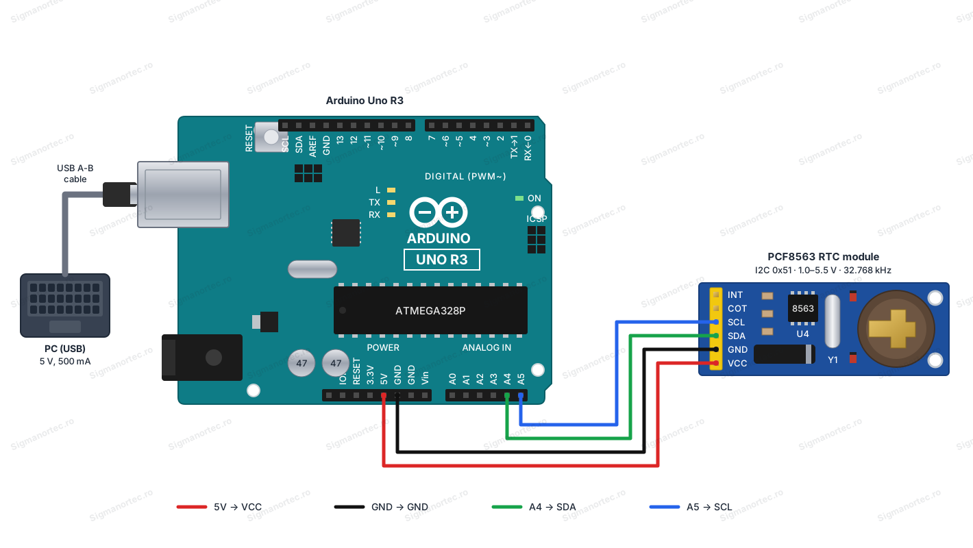
On the Arduino Uno R3 board the SDA and SCL pins next to AREF are the same signals as A4 and A5, so you can use them instead. When you connect the pins from the connector, keep in mind that the order from top to bottom on the board is INT, COT, SCL, SDA, GND, VCC. Be careful with SDA and SCL, as they are in reverse order compared to many modules. For a stable I2C bus, use short wires.
Board and libraries:
In the Arduino IDE select Tools > Board > Arduino AVR Boards > Arduino Uno. The Arduino AVR Boards package comes with the Arduino IDE, so no address needs to be added in File > Preferences. Then select the board port from Tools > Port.
The program uses only the Wire library, which comes with the Arduino IDE, so no library needs to be installed. We talk directly to the circuit registers, so you understand exactly what is read and what is written.
Code:
The program sets the clock from the compile time if the time was never set or if the battery was removed, then displays the date and time every second.
/*
  PCF8563 RTC module test
  Board: Arduino Uno (Tools > Board > Arduino AVR Boards > Arduino Uno)
  Board package: Arduino AVR Boards (comes with the Arduino IDE)
  Libraries: none to install, the Wire library comes with the Arduino IDE
  Wiring:
    RTC VCC -> Arduino 5V
    RTC GND -> Arduino GND
    RTC SDA -> Arduino A4
    RTC SCL -> Arduino A5
    RTC INT and COT are not connected
  The program sets the clock from the compile time when the time was never
  set or the backup battery was lost, then prints the date and time every second.
*/
#include <Wire.h>
const uint8_t RTC_ADDRESS = 0x51;      // 7-bit I2C address of the PCF8563
const uint8_t REG_CONTROL_1 = 0x00;    // first register, control and status 1
const uint8_t REG_SECONDS = 0x02;      // seconds register, bit 7 is the VL flag
const bool FORCE_SET_TIME = false;     // set to true to rewrite the time at every start
const char *dayNames[] = {"Sunday", "Monday", "Tuesday", "Wednesday", "Thursday", "Friday", "Saturday"};
// Convert a decimal number (0 - 99) to BCD
uint8_t decToBcd(uint8_t value) {
  return ((value / 10) << 4) | (value % 10);
}
// Convert a BCD number to decimal
uint8_t bcdToDec(uint8_t value) {
  return ((value >> 4) * 10) + (value & 0x0F);
}
// Day of the week from the date, 0 = Sunday
uint8_t dayOfWeek(uint16_t year, uint8_t month, uint8_t day) {
  static const uint8_t offsets[] = {0, 3, 2, 5, 0, 3, 5, 1, 4, 6, 2, 4};
  if (month < 3) {
    year -= 1;
  }
  return (year + year / 4 - year / 100 + year / 400 + offsets[month - 1] + day) % 7;
}
// Check if the module answers on the I2C bus
bool rtcPresent() {
  Wire.beginTransmission(RTC_ADDRESS);
  return Wire.endTransmission() == 0;
}
// Read several consecutive registers starting at startReg
bool readRegisters(uint8_t startReg, uint8_t *buffer, uint8_t length) {
  Wire.beginTransmission(RTC_ADDRESS);
  Wire.write(startReg);
  if (Wire.endTransmission() != 0) {
    return false;
  }
  if (Wire.requestFrom(RTC_ADDRESS, length) != length) {
    return false;
  }
  for (uint8_t i = 0; i < length; i++) {
    buffer[i] = Wire.read();
  }
  return true;
}
// Write the compile date and time into the clock
void setTimeFromCompileTime() {
  const char *dateText = __DATE__;   // format: "Mmm dd yyyy"
  const char *timeText = __TIME__;   // format: "hh:mm:ss"
  const char *months = "JanFebMarAprMayJunJulAugSepOctNovDec";
  char monthName[4] = {dateText[0], dateText[1], dateText[2], 0};
  uint8_t month = (strstr(months, monthName) - months) / 3 + 1;
  uint8_t day = ((dateText[4] == ' ') ? 0 : (dateText[4] - '0')) * 10 + (dateText[5] - '0');
  uint16_t year = atoi(dateText + 7);
  uint8_t hour = (timeText[0] - '0') * 10 + (timeText[1] - '0');
  uint8_t minute = (timeText[3] - '0') * 10 + (timeText[4] - '0');
  uint8_t second = (timeText[6] - '0') * 10 + (timeText[7] - '0');
  Wire.beginTransmission(RTC_ADDRESS);
  Wire.write(REG_CONTROL_1);                          // start at control register 1
  Wire.write((uint8_t)0x00);                          // control 1: clock running
  Wire.write((uint8_t)0x00);                          // control 2: no alarm or timer flags
  Wire.write(decToBcd(second));                       // seconds, bit 7 = 0 clears the VL flag
  Wire.write(decToBcd(minute));                       // minutes
  Wire.write(decToBcd(hour));                         // hours
  Wire.write(decToBcd(day));                          // day of the month
  Wire.write(dayOfWeek(year, month, day));            // day of the week
  Wire.write(decToBcd(month));                        // month, century bit 0 means 20xx
  Wire.write(decToBcd(year % 100));                   // year (00 - 99)
  Wire.endTransmission();
}
void setup() {
  Serial.begin(9600);
  Wire.begin();
  if (!rtcPresent()) {
    Serial.println("PCF8563 not found, check the wiring");
    while (true) {
      delay(1000);
    }
  }
  Serial.println("PCF8563 found at address 0x51");
  uint8_t secondsRegister = 0;
  readRegisters(REG_SECONDS, &secondsRegister, 1);
  bool vlFlag = (secondsRegister & 0x80) != 0;        // 1 = time is not guaranteed
  if (vlFlag || FORCE_SET_TIME) {
    Serial.println("Time lost or forced, setting it from compile time");
    setTimeFromCompileTime();
  }
}
void loop() {
  uint8_t data[7];
  if (!readRegisters(REG_SECONDS, data, 7)) {
    Serial.println("Read error");
    delay(1000);
    return;
  }
  bool vlFlag = (data[0] & 0x80) != 0;
  uint8_t second = bcdToDec(data[0] & 0x7F);          // mask the VL bit
  uint8_t minute = bcdToDec(data[1] & 0x7F);
  uint8_t hour = bcdToDec(data[2] & 0x3F);
  uint8_t day = bcdToDec(data[3] & 0x3F);
  uint8_t weekday = data[4] & 0x07;
  uint8_t month = bcdToDec(data[5] & 0x1F);           // mask the century bit
  uint16_t year = 2000 + bcdToDec(data[6]);
  char buffer[40];
  snprintf(buffer, sizeof(buffer), "%04u-%02u-%02u %02u:%02u:%02u ",
           (unsigned int)year, (unsigned int)month, (unsigned int)day,
           (unsigned int)hour, (unsigned int)minute, (unsigned int)second);
  Serial.print(buffer);
  Serial.print(dayNames[weekday]);
  if (vlFlag) {
    Serial.print("  WARNING: time is not guaranteed");
  }
  Serial.println();
  delay(1000);                                        // one reading per second
}
How the code works:
At the beginning are the definitions. RTC_ADDRESS is the 7-bit I2C address of the circuit, that is 0x51. REG_CONTROL_1 is the first register (0x00), and REG_SECONDS is the seconds register (0x02), whose bit 7 is the VL flag. The constant FORCE_SET_TIME, if you set it to true, rewrites the time at every start. The dayNames array contains the names of the days, in the order the program numbers them, starting from 0 for Sunday.
The functions decToBcd and bcdToDec convert between the decimal number and the BCD format used by the registers. The dayOfWeek function calculates the day of the week from the date, because the clock does not deduce it by itself and we have to write it ourselves. The rtcPresent function sends an empty transmission to address 0x51 and returns true if the module responds.
The readRegisters function sends the start register address, then requests length bytes with Wire.requestFrom and puts them in the buffer. The circuit increments the register address by itself, so a single request reads all the values from seconds to year.
The setTimeFromCompileTime function extracts the date and time from the __DATE__ and __TIME__ macros, calculates the month from the position of its name in the months string and writes the registers from 0x00 to 0x08 in order. The seconds are written with bit 7 equal to 0, which clears the VL flag, and the century bit in the month stays 0.
In setup we start the serial port at 9600 baud and the I2C bus with Wire.begin. If rtcPresent returns false, the program displays an error message and stops. Otherwise we read the seconds register, and if vlFlag is 1 or FORCE_SET_TIME is true, we call setTimeFromCompileTime.
In loop we read 7 registers from 0x02 into the data array. From each value we mask the bits that are not part of the number (0x7F for seconds and minutes, 0x3F for hours and day, 0x1F for month) and convert from BCD. The year is obtained as 2000 plus the value from the year register. The line is formatted with snprintf, printed together with the day name and, if vlFlag is 1, with a warning. At the end, delay(1000) gives one reading per second.
Result:
Open the Serial Monitor from Tools and set the speed to 9600 baud. On the first start, the messages about the module being found and the time being set appear, then one line per second with the date, time and day of the week. On the next starts the time is not set again, as long as the battery is in the holder.
PCF8563 found at address 0x51
Time lost or forced, setting it from compile time
2025-03-14 10:22:31 Friday
2025-03-14 10:22:32 Friday
2025-03-14 10:22:33 Friday
2025-03-14 10:22:34 Friday
2025-03-14 10:22:35 Friday
2025-03-14 10:22:36 Friday
Common problems:
The serial monitor shows the message PCF8563 not found. The cause is usually a wrong connection or missing power. Check that SDA goes to A4 and SCL to A5, keeping in mind that on the connector SCL is above SDA, and that VCC is at 5V and GND at GND.
Nothing appears on the serial monitor or strange characters appear. The cause is a wrong speed. Set 9600 baud in the Serial Monitor and check that the selected port is the one of the Arduino Uno board.
The time is wrong after every power cut. The cause is a missing or discharged battery in the holder, or it being installed with reversed polarity. Install a correct battery, then set FORCE_SET_TIME to true, upload the program once and set it back to false.
The warning time is not guaranteed appears. The VL flag is 1, so the supply voltage has dropped too much or the oscillator has stopped. Set the time again, and if the warning comes back, replace the battery.
The clock sets the compile time, but a few seconds late. The cause is the time between compiling and uploading the program to the board. For an exact time, set the clock from an external source, for example from the computer or from a time server.
The clock drifts by a few seconds per month. This is normal, because the accuracy depends on the crystal and the circuit does not do temperature compensation. Synchronize the clock periodically if you need better accuracy.
Limitations and tips:
The clock works between 1.0 and 5.5 V, but for I2C communication at 400 kHz the supply must be at least 1.8 V. The accuracy is given by the 32.768 kHz crystal and varies with temperature, so it does not replace a clock with temperature compensation where fractions of a second per month matter.
The module keeps the time only as long as there is a battery in good condition in the holder, and the consumption in backup mode is very low, typically 0.25 µA at 3.0 V and 25 °C. When you use the INT and COT outputs, add pull-up resistors, because both are open-drain.
Further on, you can use the alarm and the timer of the circuit, with the INT output connected to an interrupt input, to wake the board from a low-power mode. You can also use the COT output at 1 Hz as a time base for other circuits, or you can build a data logger with timestamps on an SD card.