
Product images are for informational purposes only and may vary slightly depending on the batch and supplier. Product specifications and prices may be subject to change without notice. We do our best to provide accurate and complete product specifications, but they may not be completely accurate. If you encounter any such situation, please let us know.
The product is intended for specialists and requires qualified and authorized personnel. The product does not include assembly/use instructions . Putting the product into operation by unqualified persons leads to the loss of the warranty according to the Terms and Conditions on the site.
The specified technical parameters (current, power, etc.) represent maximum allowable values under ideal operating conditions. For safe use and optimal lifespan, it is recommended to operate the product continuously at no more than 50% of the specified maximum values.
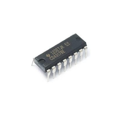
IC CD4017BE, CMOS decade counter, 10 decoded outputs, 3-18V, DIP-16
IC decade counter with 10 decoded outputs, ideal for LED sequencing, frequency division and simple automation. It works over a wide supply range, offers stable counting with reset and enable, provides low-power CMOS outputs and integrates easily into digital circuits.
Buying this product earns you 0.27 RON in loyalty points.

International fast shipping within EU. Free Shipping for orders above 100 EUR in most EU countries.

We ship from our stock within 24H

You earn points with every order, worth 5%.
The CD4017BE integrated circuit from Texas Instruments is a CMOS decade counter with 10 decoded outputs, which activates one output at a time on each clock pulse. It is suitable for sequential lights, sequencers, stepped timing, channel selectors, frequency dividers with a ratio of 10 and cascaded counting chains.
The circuit contains a 5-stage Johnson counter followed by a decoder, so at any moment only one output between Q0 and Q9 is at high level. The counter advances on the rising edge of the signal on the CLOCK pin, provided the CLOCK INHIBIT pin is at low level. A high level on the RESET pin returns the counter to Q0. The CARRY OUT output is at high level in positions Q0 - Q4 and at low level in positions Q5 - Q9, so it gives the clock frequency divided by 10 and can drive the CLOCK input of a second circuit for counting up to 100.
Main features include the CLOCK input with Schmitt trigger action, separate RESET and CLOCK INHIBIT inputs, the 10 decoded outputs Q0 - Q9, the CARRY OUT output, static operation and the DIP-16 package for through-hole mounting. The supply is 3 - 18 VDC, between pin VDD (16) and pin VSS (8).
Specifications:
Supply voltage: 3 - 18 VDC
Manufacturer: Texas Instruments
Logic family: CD4000 (CMOS)
Circuit type: 5-stage Johnson counter with decoder, decade
Outputs: 10 decoded (Q0 - Q9) and CARRY OUT
Control inputs: CLOCK, RESET, CLOCK INHIBIT
Counting trigger: Rising edge on CLOCK, with Schmitt trigger input
Operating mode: Static
Operating temperature: -55 - 125 °C
Package: DIP-16 (PDIP-16), through-hole mounting
Pinout:
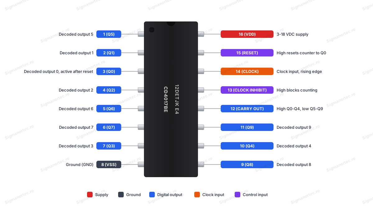
| Connector | Pin | Function |
|---|---|---|
| DIP-16 | 1 (Q5) | Decoded output 5 |
| DIP-16 | 2 (Q1) | Decoded output 1 |
| DIP-16 | 3 (Q0) | Decoded output 0, active after RESET |
| DIP-16 | 4 (Q2) | Decoded output 2 |
| DIP-16 | 5 (Q6) | Decoded output 6 |
| DIP-16 | 6 (Q7) | Decoded output 7 |
| DIP-16 | 7 (Q3) | Decoded output 3 |
| DIP-16 | 8 (VSS) | Ground (GND) |
| DIP-16 | 9 (Q8) | Decoded output 8 |
| DIP-16 | 10 (Q4) | Decoded output 4 |
| DIP-16 | 11 (Q9) | Decoded output 9 |
| DIP-16 | 12 (CARRY OUT) | Carry output, high level in positions Q0 - Q4 and low level in positions Q5 - Q9 |
| DIP-16 | 13 (CLOCK INHIBIT) | High level blocks counting, low level allows it |
| DIP-16 | 14 (CLOCK) | Clock input, counts on rising edge |
| DIP-16 | 15 (RESET) | High level returns the counter to Q0 |
| DIP-16 | 16 (VDD) | Supply 3 - 18 VDC |
Usage:
Mount the circuit with the notch of the package facing left, so that pin 1 is the first pin at the bottom left, and the pins are numbered counterclockwise.
Power the circuit between pin VDD (16) and pin VSS (8), with a voltage between 3 and 18 VDC, respecting polarity.
Mount a 100 nF ceramic capacitor between pins 16 and 8, as close as possible to the circuit, so that switching pulses do not cause false counts.
Never leave the RESET and CLOCK INHIBIT pins unconnected. Connect them to ground for normal operation or to a control signal.
Apply the clock signal to the CLOCK pin. On each rising edge, the high level passes from one output to the next, from Q0 to Q9, then the cycle restarts.
To block counting, bring the CLOCK INHIBIT pin to high level. Clock pulses are ignored until the pin returns to low level.
To return the counter to Q0, briefly bring the RESET pin to high level, then back to low level.
For a shorter cycle of 10 steps, connect the desired output Qn to the RESET pin. The counter will go through positions Q0 to Qn-1, then reset.
For counting up to 100, connect the CARRY OUT output of the first circuit to the CLOCK pin of the second.
The outputs can supply a small current, so do not connect LEDs directly to them. Use a transistor or a buffer circuit and a current-limiting resistor.
The circuit is CMOS, so handle it carefully against electrostatic discharges and do not apply to the inputs voltages higher than the supply voltage.
- Supply voltage
- 3-18 V DC
- Type
- 5-stage Johnson counter with decoder, decade
- Operating temperature
- -55-125 °C
- Output type
- 10 decoded (Q0 - Q9) and CARRY OUT
- Mounting
- through-hole (THT)
- Manufacturer
- Texas Instruments
- Package
- DIP-16 (PDIP-16)
Produs destinat utilizarii in proiecte electronice, automatizari, prototipare, educatie si cercetare.
Produsul trebuie utilizat numai conform specificatiilor tehnice mentionate in descriere si/sau in documentatia produsului.
Avertismente generale de siguranta:
Nu utilizati produsul la tensiuni, curenti sau temperaturi peste valorile specificate.
Montajul si conectarea trebuie realizate de persoane cu cunostinte tehnice minime in domeniul electric/electronic.
Evitati scurtcircuitele, inversarea polaritatii si conectarea gresita a alimentarii.
Nu lasati produsul alimentat nesupravegheat in timpul testelor.
Produsul nu este jucarie si nu este destinat copiilor.
Pentru modulele electronice, se recomanda utilizarea in carcase, panouri sau montaje protejate, dupa caz.
Identificare produs:
Denumirea produsului, codul/SKU-ul si caracteristicile tehnice sunt mentionate in pagina produsului si/sau pe eticheta ambalajului.
Producator / Importator / Distribuitor:
Sigmanortec S.R.L.
Calea Bucuresti nr. 9, Targu Jiu, Gorj, Romania
E-mail: [email protected]
Website: www.sigmanortec.ro
Persoana responsabila in UE:
Sigmanortec S.R.L.
Calea Bucuresti nr. 9, Targu Jiu, Gorj, Romania
E-mail: [email protected]
Documentatie si siguranta:
Pentru informatii suplimentare, fise tehnice, declaratii de conformitate sau instructiuni, ne puteti contacta la [email protected].
Reviews (9) - Review moderation

Functioneaza corect.
circuite integrate standard corect livrate
recomandat...
bun
Recomand
/*
  CD4017BE decade counter test

  Board: Arduino Uno (Arduino AVR Boards, installed with Arduino IDE)
  Libraries: none, only the core Arduino functions are used

  Wiring (CD4017BE pin -> Arduino Uno pin):
    VDD (16)           -> 5V
    VSS (8)            -> GND
    CLOCK (14)         -> D2
    RESET (15)         -> D3
    CLOCK INHIBIT (13) -> D4
    Q0 (3)  -> D5
    Q1 (2)  -> D6
    Q2 (4)  -> D7
    Q3 (7)  -> D8
    Q4 (10) -> D9
    Q5 (1)  -> D10
    Q6 (5)  -> D11
    Q7 (6)  -> D12
    Q8 (9)  -> A0
    Q9 (11) -> A1
    CARRY OUT (12) -> A2
  A 100 nF ceramic capacitor goes between pins 16 and 8.
*/

const uint8_t PIN_CLOCK   = 2;   // Clock input of the counter
const uint8_t PIN_RESET   = 3;   // Reset input, HIGH sets the counter to Q0
const uint8_t PIN_INHIBIT = 4;   // Clock inhibit, HIGH blocks counting
const uint8_t PIN_CARRY   = A2;  // Carry out output

// Arduino pins connected to outputs Q0 - Q9, in order
const uint8_t OUT_PINS[10] = {5, 6, 7, 8, 9, 10, 11, 12, A0, A1};

int seq[10];    // Active output after each clock pulse
int carry[10];  // Carry out level after each clock pulse

// Send one clock pulse, the counter advances on the rising edge
void pulseClock() {
  digitalWrite(PIN_CLOCK, HIGH);
  delayMicroseconds(20);
  digitalWrite(PIN_CLOCK, LOW);
  delayMicroseconds(20);
}

// Send a short reset pulse, the counter returns to Q0
void resetCounter() {
  digitalWrite(PIN_RESET, HIGH);
  delayMicroseconds(20);
  digitalWrite(PIN_RESET, LOW);
  delayMicroseconds(20);
}

// Return the number of the single HIGH output, or -1 if not exactly one is HIGH
int readActiveOutput() {
  int active = -1;
  int count = 0;
  for (int i = 0; i < 10; i++) {
    if (digitalRead(OUT_PINS[i]) == HIGH) {
      active = i;
      count++;
    }
  }
  if (count != 1) {
    return -1;
  }
  return active;
}

// Print the output name, for example Q3
void printOutput(int index) {
  if (index < 0) {
    Serial.print("Q?");
  } else {
    Serial.print("Q");
    Serial.print(index);
  }
}

void setup() {
  Serial.begin(9600);

  pinMode(PIN_CLOCK, OUTPUT);
  pinMode(PIN_RESET, OUTPUT);
  pinMode(PIN_INHIBIT, OUTPUT);
  pinMode(PIN_CARRY, INPUT);
  for (int i = 0; i < 10; i++) {
    pinMode(OUT_PINS[i], INPUT);
  }

  digitalWrite(PIN_CLOCK, LOW);
  digitalWrite(PIN_RESET, LOW);
  digitalWrite(PIN_INHIBIT, LOW);   // LOW allows counting

  Serial.println("CD4017 test started");
}

void loop() {
  // Step 1: reset the counter and show the start position
  resetCounter();
  Serial.print("Reset: active output ");
  printOutput(readActiveOutput());
  Serial.println();

  // Step 2: ten clock pulses, record the outputs after each one
  for (int i = 0; i < 10; i++) {
    pulseClock();
    seq[i] = readActiveOutput();
    carry[i] = digitalRead(PIN_CARRY);
  }

  Serial.print("Sequence after each clock pulse: ");
  for (int i = 0; i < 10; i++) {
    printOutput(seq[i]);
    Serial.print(" ");
  }
  Serial.println();

  Serial.print("Carry out after each pulse:      ");
  for (int i = 0; i < 10; i++) {
    Serial.print(" ");
    Serial.print(carry[i]);
    Serial.print(" ");
  }
  Serial.println();

  if (seq[9] == 0) {
    Serial.println("Result: counter wrapped back to Q0 after 10 pulses");
  } else {
    Serial.println("Error: counter did not return to Q0, check wiring");
  }

  // Step 3: clock inhibit HIGH, pulses must be ignored
  digitalWrite(PIN_INHIBIT, HIGH);
  for (int i = 0; i < 3; i++) {
    pulseClock();
  }
  Serial.print("Clock inhibit HIGH, 3 pulses: output stays ");
  printOutput(readActiveOutput());
  Serial.println();

  // Step 4: clock inhibit LOW, one pulse moves the counter
  digitalWrite(PIN_INHIBIT, LOW);
  pulseClock();
  Serial.print("Clock inhibit LOW, 1 pulse: output moves to ");
  printOutput(readActiveOutput());
  Serial.println();

  // Step 5: reset returns the counter to Q0
  resetCounter();
  Serial.print("Reset HIGH: output returns to ");
  printOutput(readActiveOutput());
  Serial.println();

  delay(3000);   // Wait before repeating the test
}
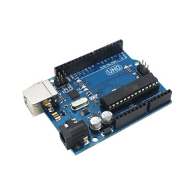
This tutorial uses the Arduino Uno board, which generates the clock signal for the CD4017BE integrated circuit and reads the state of its outputs. The Arduino Uno is a suitable choice because it works at 5 V, the voltage at which the CD4017BE works directly, and the 10 outputs plus the carry output can be read with the digital pins of the board.
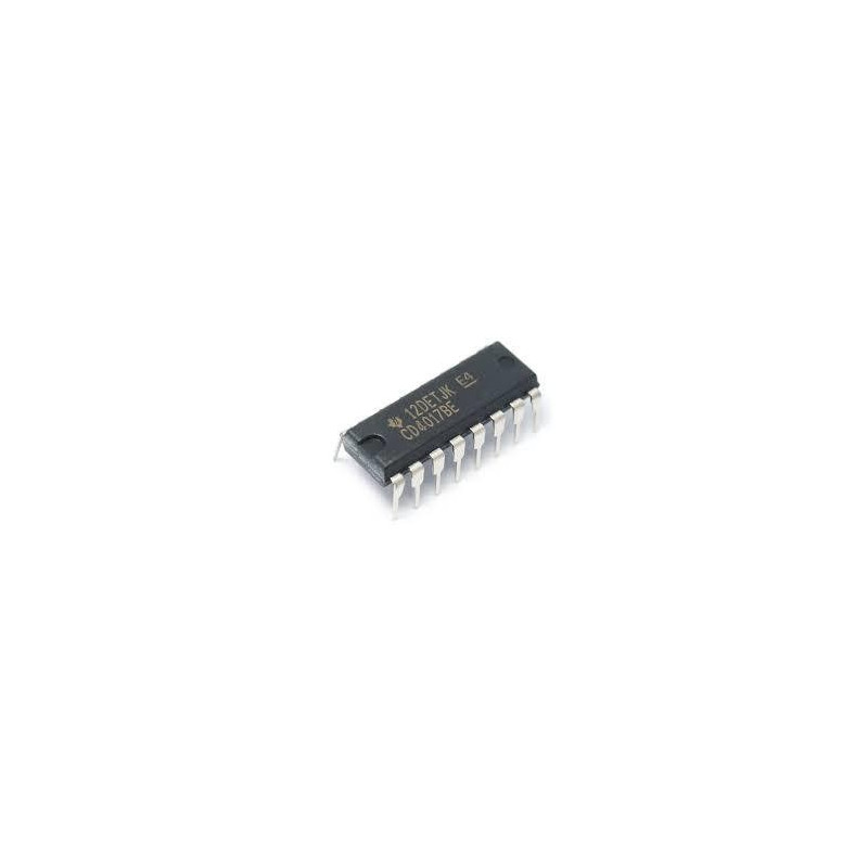
The CD4017BE is a CMOS decade counter with 10 decoded outputs, in a DIP-16 package. On each clock pulse, the high level moves from one output to the next, from Q0 to Q9, and then the circuit starts over. It is used in sequential lights, sequencers, step timers, channel selectors and frequency dividers with a ratio of 10.
How it works:
The CD4017BE contains a 5-stage Johnson counter, followed by a decoder. Thanks to the decoder, at any moment only one output between Q0 and Q9 is at high level, while the other nine are at low level. Each output stays at high level for exactly one full period of the clock signal.
The counter advances on the rising edge of the signal at the CLOCK pin, provided that the CLOCK INHIBIT pin is at low level. If CLOCK INHIBIT is at high level, the clock pulses are ignored and the counter stays in place. A high level on the RESET pin brings the counter to the zero position, meaning Q0 becomes high and the other outputs low. The RESET and CLOCK INHIBIT pins should never be left floating, they must be connected either to VDD or to ground.
The CARRY OUT output is at high level while the counter is in positions Q0 - Q4, and at low level in positions Q5 - Q9. It completes a full cycle every 10 clock pulses, so the frequency at CARRY OUT is the clock frequency divided by 10. For example, a 1000 Hz clock gives 100 Hz at CARRY OUT. Each output Qn also has the clock frequency divided by 10, but it stays high for only one tenth of the period. The CARRY OUT output is connected to the CLOCK input of a second CD4017BE to count up to 100.
The circuit operates between 3 V and 18 V. In this tutorial we power it from 5 V, from the Arduino board, so that the output levels are compatible with the Arduino Uno pins.
Connection:
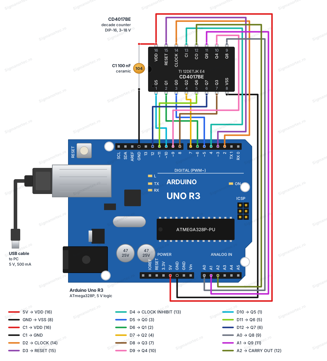
Place the circuit on the breadboard with the notch of the package to the left, so that pin 1 is the first pin at the bottom left. Power the circuit from 5 V and connect a 100 nF ceramic capacitor between pins 16 and 8, as close as possible to the circuit, so that the switching spikes do not cause false counts. The CD4017BE outputs at 5 V can supply only a very small current, so do not connect LEDs directly to them in this setup. We read them only with the digital inputs of the Arduino board. Do not use pin D13 for an output, because it has the board LED connected and would load the output. The logic levels are 5 V, so no level converter is needed, and since RESET and CLOCK INHIBIT are driven by the board, no pull-up resistors are required.
| IC pin | Connect to | Role |
|---|---|---|
| VDD (pin 16) | Arduino 5V | Circuit power supply |
| VSS (pin 8) | Arduino GND | Ground |
| 100 nF capacitor (104) | Between pin 16 and GND | Power supply decoupling, as close as possible to the circuit |
| CLOCK (pin 14) | D2 | Clock input, counts on the rising edge |
| RESET (pin 15) | D3 | A high level brings the counter to Q0 |
| CLOCK INHIBIT (pin 13) | D4 | High level blocks counting, low level allows it |
| Q0 (pin 3) | D5 | Output 0 |
| Q1 (pin 2) | D6 | Output 1 |
| Q2 (pin 4) | D7 | Output 2 |
| Q3 (pin 7) | D8 | Output 3 |
| Q4 (pin 10) | D9 | Output 4 |
| Q5 (pin 1) | D10 | Output 5 |
| Q6 (pin 5) | D11 | Output 6 |
| Q7 (pin 6) | D12 | Output 7 |
| Q8 (pin 9) | A0 | Output 8 |
| Q9 (pin 11) | A1 | Output 9 |
| CARRY OUT (pin 12) | A2 | Carry output, high in positions Q0 - Q4 |
Board and libraries:
In the Arduino IDE, select the Arduino Uno board from Tools > Board, from the Arduino AVR Boards package, which comes installed with the Arduino IDE. The program uses only the basic functions of Arduino, so no library needs to be installed.
The code:
The program resets the counter, sends 10 clock pulses, reads the active output and CARRY OUT after each pulse, and then checks the RESET and CLOCK INHIBIT pins.
/*
  CD4017BE decade counter test
  Board: Arduino Uno (Arduino AVR Boards, installed with Arduino IDE)
  Libraries: none, only the core Arduino functions are used
  Wiring (CD4017BE pin -> Arduino Uno pin):
    VDD (16)           -> 5V
    VSS (8)            -> GND
    CLOCK (14)         -> D2
    RESET (15)         -> D3
    CLOCK INHIBIT (13) -> D4
    Q0 (3)  -> D5
    Q1 (2)  -> D6
    Q2 (4)  -> D7
    Q3 (7)  -> D8
    Q4 (10) -> D9
    Q5 (1)  -> D10
    Q6 (5)  -> D11
    Q7 (6)  -> D12
    Q8 (9)  -> A0
    Q9 (11) -> A1
    CARRY OUT (12) -> A2
  A 100 nF ceramic capacitor goes between pins 16 and 8.
*/
const uint8_t PIN_CLOCK   = 2;   // Clock input of the counter
const uint8_t PIN_RESET   = 3;   // Reset input, HIGH sets the counter to Q0
const uint8_t PIN_INHIBIT = 4;   // Clock inhibit, HIGH blocks counting
const uint8_t PIN_CARRY   = A2;  // Carry out output
// Arduino pins connected to outputs Q0 - Q9, in order
const uint8_t OUT_PINS[10] = {5, 6, 7, 8, 9, 10, 11, 12, A0, A1};
int seq[10];    // Active output after each clock pulse
int carry[10];  // Carry out level after each clock pulse
// Send one clock pulse, the counter advances on the rising edge
void pulseClock() {
  digitalWrite(PIN_CLOCK, HIGH);
  delayMicroseconds(20);
  digitalWrite(PIN_CLOCK, LOW);
  delayMicroseconds(20);
}
// Send a short reset pulse, the counter returns to Q0
void resetCounter() {
  digitalWrite(PIN_RESET, HIGH);
  delayMicroseconds(20);
  digitalWrite(PIN_RESET, LOW);
  delayMicroseconds(20);
}
// Return the number of the single HIGH output, or -1 if not exactly one is HIGH
int readActiveOutput() {
  int active = -1;
  int count = 0;
  for (int i = 0; i < 10; i++) {
    if (digitalRead(OUT_PINS[i]) == HIGH) {
      active = i;
      count++;
    }
  }
  if (count != 1) {
    return -1;
  }
  return active;
}
// Print the output name, for example Q3
void printOutput(int index) {
  if (index < 0) {
    Serial.print("Q?");
  } else {
    Serial.print("Q");
    Serial.print(index);
  }
}
void setup() {
  Serial.begin(9600);
  pinMode(PIN_CLOCK, OUTPUT);
  pinMode(PIN_RESET, OUTPUT);
  pinMode(PIN_INHIBIT, OUTPUT);
  pinMode(PIN_CARRY, INPUT);
  for (int i = 0; i < 10; i++) {
    pinMode(OUT_PINS[i], INPUT);
  }
  digitalWrite(PIN_CLOCK, LOW);
  digitalWrite(PIN_RESET, LOW);
  digitalWrite(PIN_INHIBIT, LOW);   // LOW allows counting
  Serial.println("CD4017 test started");
}
void loop() {
  // Step 1: reset the counter and show the start position
  resetCounter();
  Serial.print("Reset: active output ");
  printOutput(readActiveOutput());
  Serial.println();
  // Step 2: ten clock pulses, record the outputs after each one
  for (int i = 0; i < 10; i++) {
    pulseClock();
    seq[i] = readActiveOutput();
    carry[i] = digitalRead(PIN_CARRY);
  }
  Serial.print("Sequence after each clock pulse: ");
  for (int i = 0; i < 10; i++) {
    printOutput(seq[i]);
    Serial.print(" ");
  }
  Serial.println();
  Serial.print("Carry out after each pulse:      ");
  for (int i = 0; i < 10; i++) {
    Serial.print(" ");
    Serial.print(carry[i]);
    Serial.print(" ");
  }
  Serial.println();
  if (seq[9] == 0) {
    Serial.println("Result: counter wrapped back to Q0 after 10 pulses");
  } else {
    Serial.println("Error: counter did not return to Q0, check wiring");
  }
  // Step 3: clock inhibit HIGH, pulses must be ignored
  digitalWrite(PIN_INHIBIT, HIGH);
  for (int i = 0; i < 3; i++) {
    pulseClock();
  }
  Serial.print("Clock inhibit HIGH, 3 pulses: output stays ");
  printOutput(readActiveOutput());
  Serial.println();
  // Step 4: clock inhibit LOW, one pulse moves the counter
  digitalWrite(PIN_INHIBIT, LOW);
  pulseClock();
  Serial.print("Clock inhibit LOW, 1 pulse: output moves to ");
  printOutput(readActiveOutput());
  Serial.println();
  // Step 5: reset returns the counter to Q0
  resetCounter();
  Serial.print("Reset HIGH: output returns to ");
  printOutput(readActiveOutput());
  Serial.println();
  delay(3000);   // Wait before repeating the test
}
How the code works:
At the beginning the pins are defined: PIN_CLOCK (D2), PIN_RESET (D3), PIN_INHIBIT (D4) and PIN_CARRY (A2). The OUT_PINS array contains, in order, the Arduino pins connected to the outputs Q0 - Q9. The seq and carry arrays store the active output and the CARRY OUT level after each clock pulse.
The pulseClock() function brings the clock pin to high level for 20 microseconds, then to low level, so it produces a rising edge at which the counter advances by one position. The resetCounter() function sends a short pulse on the RESET pin and brings the counter back to Q0.
The readActiveOutput() function reads the 10 outputs and returns the number of the only output at high level. If there is not exactly one high output, it returns -1, which indicates a connection problem. The printOutput() function displays the output name, for example Q3, or Q? when the value is not valid.
In setup() the serial port is started at 9600 baud, the CLOCK, RESET and CLOCK INHIBIT pins are configured as outputs, and the reading pins as inputs. The three control pins are brought to low level, so counting is enabled.
In loop() five steps are executed. First the counter is reset and the start position is displayed. Then 10 clock pulses are sent and the active output and the CARRY OUT level are stored. If after the tenth pulse the active output is Q0 again, the counter has completed a full cycle. In step 3 the CLOCK INHIBIT pin is brought to high level and 3 pulses are sent, which must be ignored. In step 4 the pin returns to low level and a single pulse moves the counter to Q1. In step 5 a new reset brings the counter back to Q0, then the program waits 3 seconds and repeats the test.
Result:
Open the Serial Monitor in the Arduino IDE at 9600 baud. At each test cycle you will see the position after the reset, the sequence of outputs after each clock pulse, the CARRY OUT level (1 in positions Q0 - Q4 and 0 in positions Q5 - Q9) and the results of the checks for CLOCK INHIBIT and RESET.
CD4017 test started
Reset: active output Q0
Sequence after each clock pulse: Q1 Q2 Q3 Q4 Q5 Q6 Q7 Q8 Q9 Q0
Carry out after each pulse:       1  1  1  1  0  0  0  0  0  1
Result: counter wrapped back to Q0 after 10 pulses
Clock inhibit HIGH, 3 pulses: output stays Q0
Clock inhibit LOW, 1 pulse: output moves to Q1
Reset HIGH: output returns to Q0
Common problems:
The Serial Monitor shows Q? instead of an output. The cause is usually a wrong connection or missing power to the circuit, so that there is not exactly one output at high level. Check pins 16 and 8, and the correspondence between outputs Q0 - Q9 and pins D5 - D12, A0 and A1.
The counter skips positions or counts several times per pulse. The cause is usually the missing 100 nF capacitor between pins 16 and 8, or long wires on the CLOCK pin. Mount the capacitor close to the circuit and shorten the wires.
The counter always stays on the same output. Check that the CLOCK INHIBIT pin (13) is at low level and that the CLOCK pin (14) is connected to D2. A RESET pin left at high level keeps the counter at Q0.
The results are unstable or different on each run. The RESET and CLOCK INHIBIT pins are probably left unconnected. Connect them to D3 and D4 as shown in the table.
The outputs look weak, or the high level drops when a load is added. The outputs can supply only a small current, so do not connect LEDs or other loads directly to them. Use a transistor or a buffer circuit.
Limitations and tips:
The circuit operates between 3 V and 18 V, but in this setup you power it only from 5 V. At a higher voltage, the outputs would exceed the level accepted by the Arduino Uno pins. The maximum clock frequency increases with the supply voltage, and at 5 V it is well above the speed used in this test.
The outputs have a low current capability, so for LEDs, relays or other loads use an amplifier stage with transistors or a driver circuit.
You can further build a 10-step sequencer, a light sequence, a frequency divider with a ratio of 10 or a counter up to 100, by connecting the CARRY OUT output to the CLOCK input of a second CD4017BE. For a shorter cycle, connect the desired Qn output to the RESET pin.