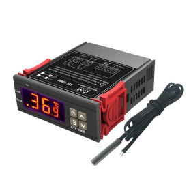

Product images are for informational purposes only and may vary slightly depending on the batch and supplier. Product specifications and prices may be subject to change without notice. We do our best to provide accurate and complete product specifications, but they may not be completely accurate. If you encounter any such situation, please let us know.
The product is intended for specialists and requires qualified and authorized personnel. The product does not include assembly/use instructions . Putting the product into operation by unqualified persons leads to the loss of the warranty according to the Terms and Conditions on the site.
The specified technical parameters (current, power, etc.) represent maximum allowable values under ideal operating conditions. For safe use and optimal lifespan, it is recommended to operate the product continuously at no more than 50% of the specified maximum values.
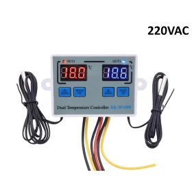
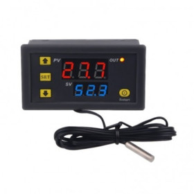
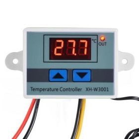
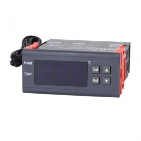
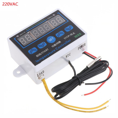
XH-W1411 thermostat module, heating-cooling, LED display, temperature control, 220VAC
Digital thermostat with a 10 A relay output, which automatically controls heating or cooling based on an NTC probe with a 1-meter cable. Three LED displays show the start temperature, the current temperature, and the stop temperature, with measurement ranging from -50 °C to 110 °C. Includes F-1, F-2, and F-3 timing modes and stores settings during power loss.
Buying this product earns you 2.14 RON in loyalty points.

International fast shipping within EU. Free Shipping for orders above 100 EUR in most EU countries.

We ship from our stock within 24H

You earn points with every order, worth 5%.
The XH-W1411 (W88) thermostat module is a digital temperature controller with relay output, which turns a heating device, cooling device, or other temperature-sensitive equipment on and off based on the value measured by an NTC probe. It has three LED displays that simultaneously show the start temperature, current temperature, and stop temperature, and its timing functions also allow intermittent operation, with scheduled shutoff or startup. It is suitable for greenhouses, aquariums, incubators, terrariums, technical rooms, and any application where a 220 VAC load must be controlled based on temperature or time.
The module measures temperatures between -50 °C and 110 °C, with a resolution of 0.1 °C, and the control range is -19 °C to 99 °C. The control type is On/Off, and the operating mode results from the relationship between the two set values. If the start temperature is lower than the stop temperature, the module works in heating mode. If the start temperature is higher than the stop temperature, the module works in cooling mode. In addition to the thermostat function, the module has three timing modes, F-1 (intermittent operation, 1 - 99 minutes), F-2 (scheduled shutoff), and F-3 (scheduled startup), the last two of which can reach up to 99 hours and 99 minutes. Settings are retained in memory when power is interrupted.
Among the main features are three LED displays with two or three digits each, five buttons (four UP / DOWN arrows and the SET button), two LEDs that show the output status, the 250 VAC, 10 A relay with output on two yellow wires marked LOAD, the NTC probe with a 1 meter cable, and two mounting ears with 3 mm holes. Power is supplied directly from the 220 VAC mains, through the wires marked POWER.
The module operates independently, without a development board and without programming, and its output acts as a closed / open contact that can directly control heaters, fans, pumps, or other mains loads, within the 10 A limit.
Specifications:
Supply voltage: 220 VAC
Maximum relay current: 10 A
Maximum relay contact voltage: 250 VAC
Temperature measuring range: -50 °C to 110 °C
Temperature control range: -19 °C to 99 °C
Accuracy: ±0.1 °C
Display resolution: 0.1 °C
Timer hour limit: 99 hours
Timer minute limit: 99 minutes
Control mode: On/Off
Temperature sensor: NTC probe (negative temperature coefficient)
Probe cable length: 1 m
Display: 3 LED displays (start temperature, current temperature, stop temperature)
Buttons: 4 UP / DOWN arrows and SET button
Indicators: 2 output status LEDs
Memory: Settings are retained when power is interrupted
Mounting ear hole diameter: 3 mm
Dimensions: 75 x 55 x 31 mm
Layout:
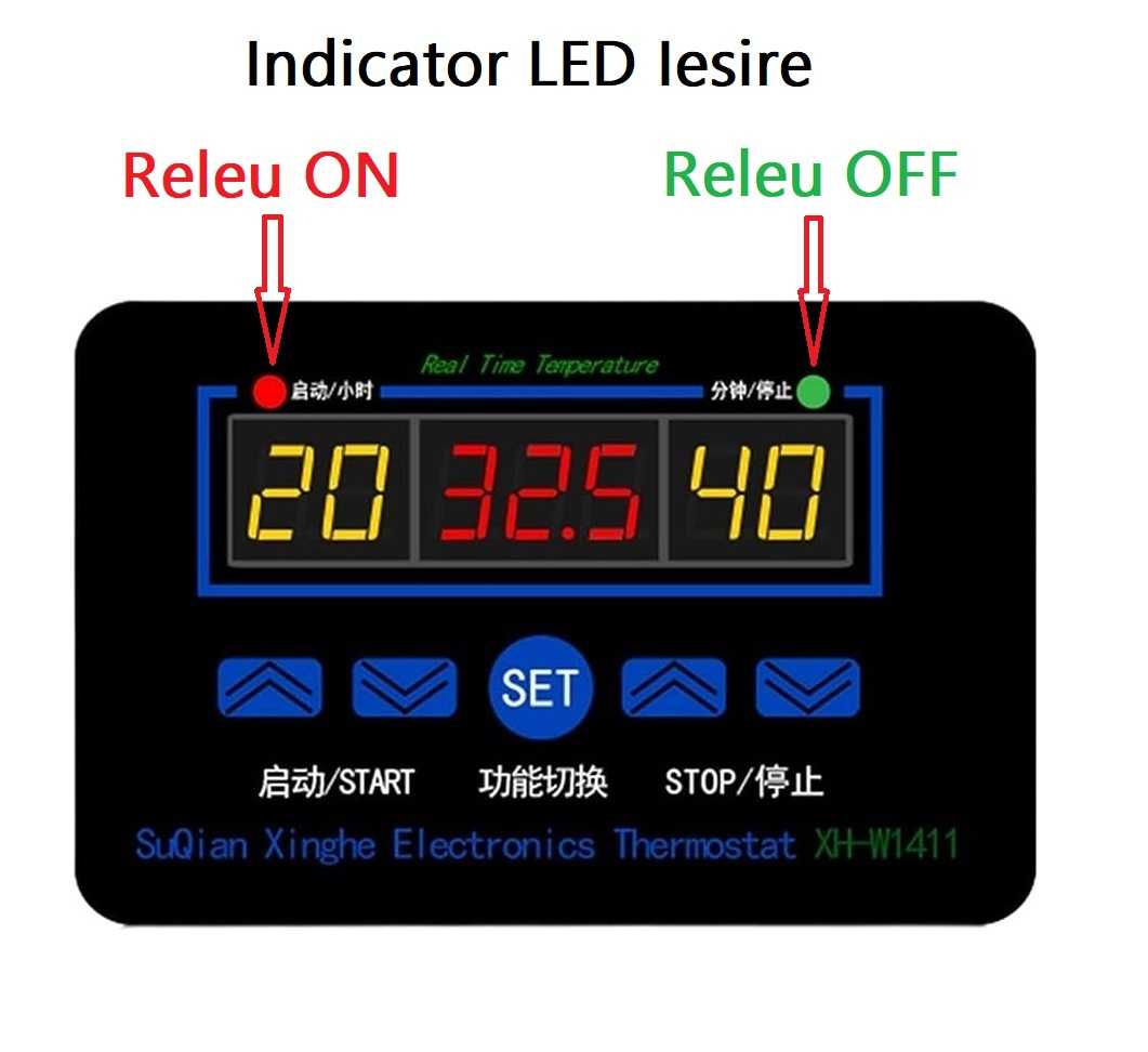
| Element | Function |
|---|---|
| Left display | Shows the start temperature in thermostat mode. In F-1 mode it shows the ON time in minutes, and in F-2 and F-3 modes it shows the hours. |
| Middle display | Shows the current temperature measured by the probe. When a timing function is selected, it shows the module operating mode (F-1, F-2, or F-3). |
| Right display | Shows the stop temperature in thermostat mode. In F-1 mode it shows the OFF time in minutes, and in F-2 and F-3 modes it shows the minutes. |
| Red LED (top left) | Indicates relay ON, meaning the LOAD output is active. |
| Green LED (top right) | Indicates relay OFF, meaning the LOAD output is off. |
| Left UP / DOWN buttons (START) | Increase or decrease the start temperature. In F-1 mode they adjust the ON time, and in F-2 and F-3 modes they adjust the hours. When powered on with the buttons pressed, the two left arrows activate self-diagnosis. |
| SET button | A short press selects functions F-1, F-2, and F-3. Held for a few seconds, it stops or starts the module. Pressed while powering on, it enters temperature calibration. |
| Right UP / DOWN buttons (STOP) | Increase or decrease the stop temperature. In F-1 mode they adjust the OFF time, and in F-2 and F-3 modes they adjust the minutes. When powered on with the buttons pressed, the two right arrows restore the module to factory settings. |
| POWER wires (red and black) | 220 VAC power input, phase (L) and neutral (N). |
| LOAD wires (two yellow wires) | 250 VAC, 10 A relay output, which acts as a closed / open contact in series with the load. |
| NTC probe | Temperature sensor, with 1 meter cable, already attached to the module. |
| Mounting ears | Two ears with 3 mm holes for mounting the module. |
Pinout:
| Connector | Pin | Function |
|---|---|---|
| POWER (red wire) | L / N | 220 VAC power supply |
| POWER (black wire) | N / L | 220 VAC power supply |
| LOAD (yellow wire) | 1 | Relay contact, connect to mains phase |
| LOAD (yellow wire) | 2 | Relay contact, connect to the load |
| NTC (black cable) | - | Attached NTC temperature probe |
Usage:
Warning: the module operates at 220 VAC mains voltage, which is dangerous and can cause severe electric shock. Connections must be made only with the product disconnected from the mains, by a qualified person.
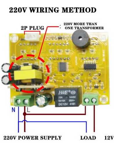
Connect the POWER wires to the phase (L) and neutral (N) of the mains, correctly observing the two conductors.
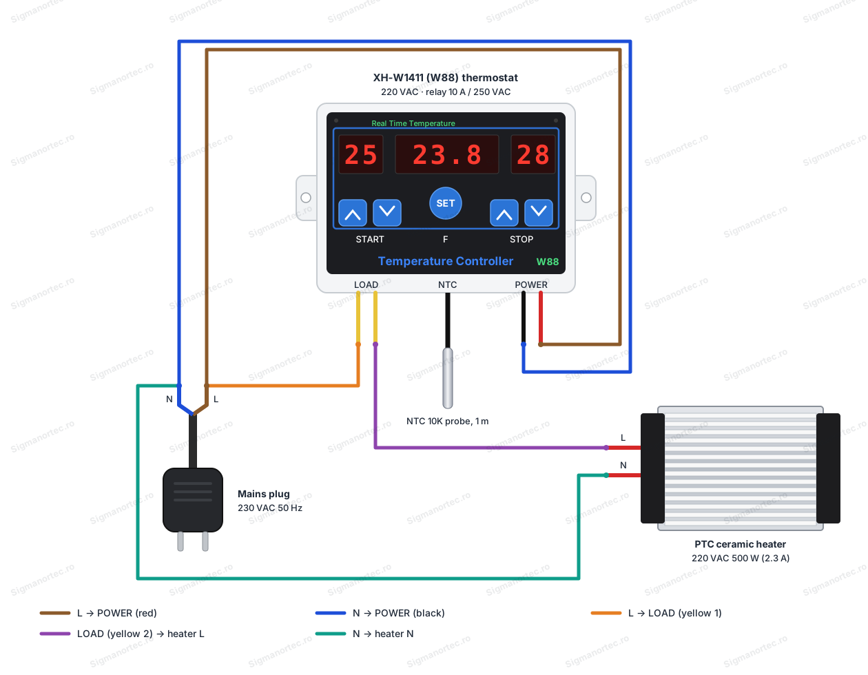
Connect the load through the LOAD wires, with one yellow wire to the mains phase and the other yellow wire to the load, and the second wire of the load to neutral. The relay remains in series with the load, on the phase wire.
Do not exceed 10 A and 250 VAC on the relay contacts, and for metal enclosures also connect the protective earth.
Place the NTC probe in the location where temperature must be measured, without exposing it directly to the heat source or to the cold air jet of the controlled device.
Power the module. The displays light up, and the current temperature appears in the middle.
Set the start temperature with the left UP / DOWN buttons and the stop temperature with the right UP / DOWN buttons, following the values on the left and right displays.
For heating, set the start temperature lower than the stop temperature. For example, start 25 and stop 28 will turn the heater on below 25 °C and off at 28 °C.
For cooling, set the start temperature higher than the stop temperature. For example, start 35 and stop 32 will turn the fan on above 35 °C and off at 32 °C.
Check operation using the LEDs. The red LED lights when the output is active, and the green LED lights when the output is off.
Briefly press the SET button to select functions F-1, F-2, or F-3, indicated on the middle display. These functions do not work together with the thermostat, and the thermostat works when the current temperature is shown in the middle.
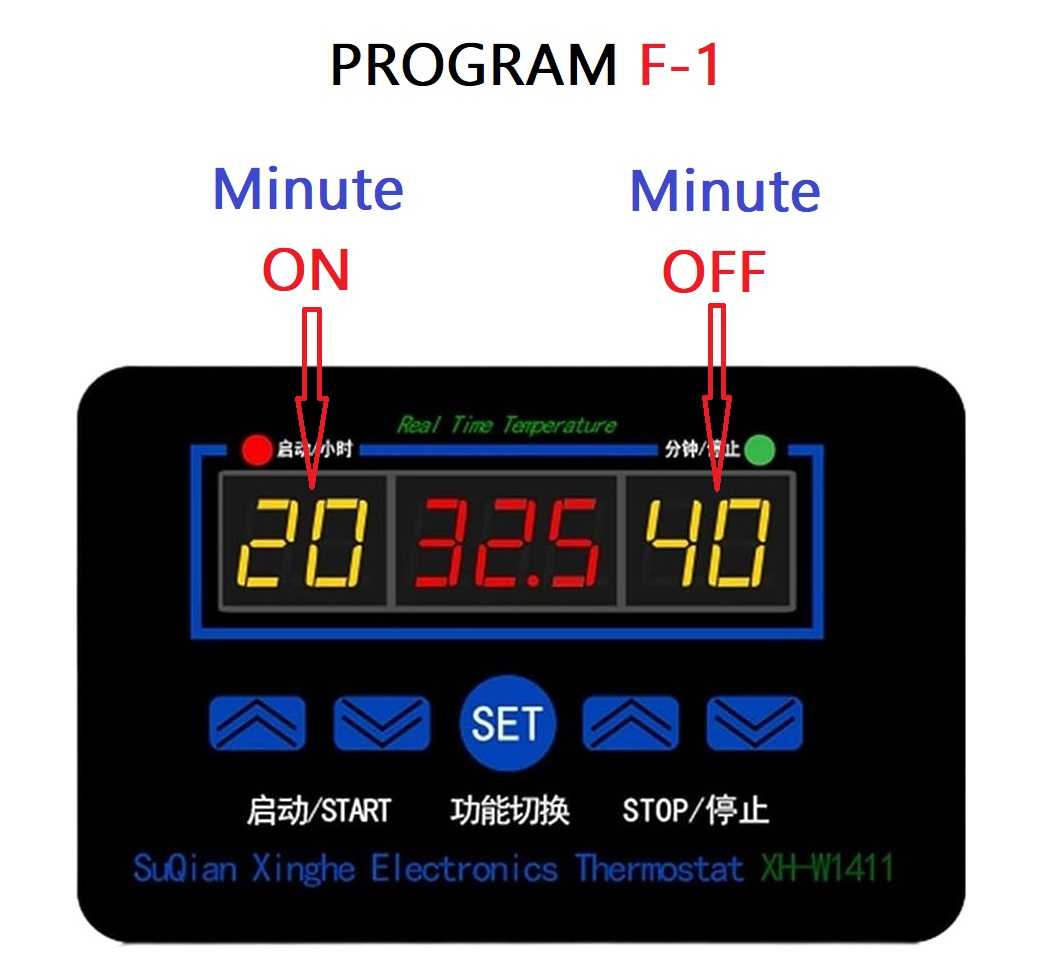
In F-1 mode, set the ON time with the left buttons and the OFF time with the right buttons, in minutes, between 1 and 99.
In F-2 mode, set the hours with the left buttons and the minutes with the right buttons, up to 99 hours and 99 minutes.
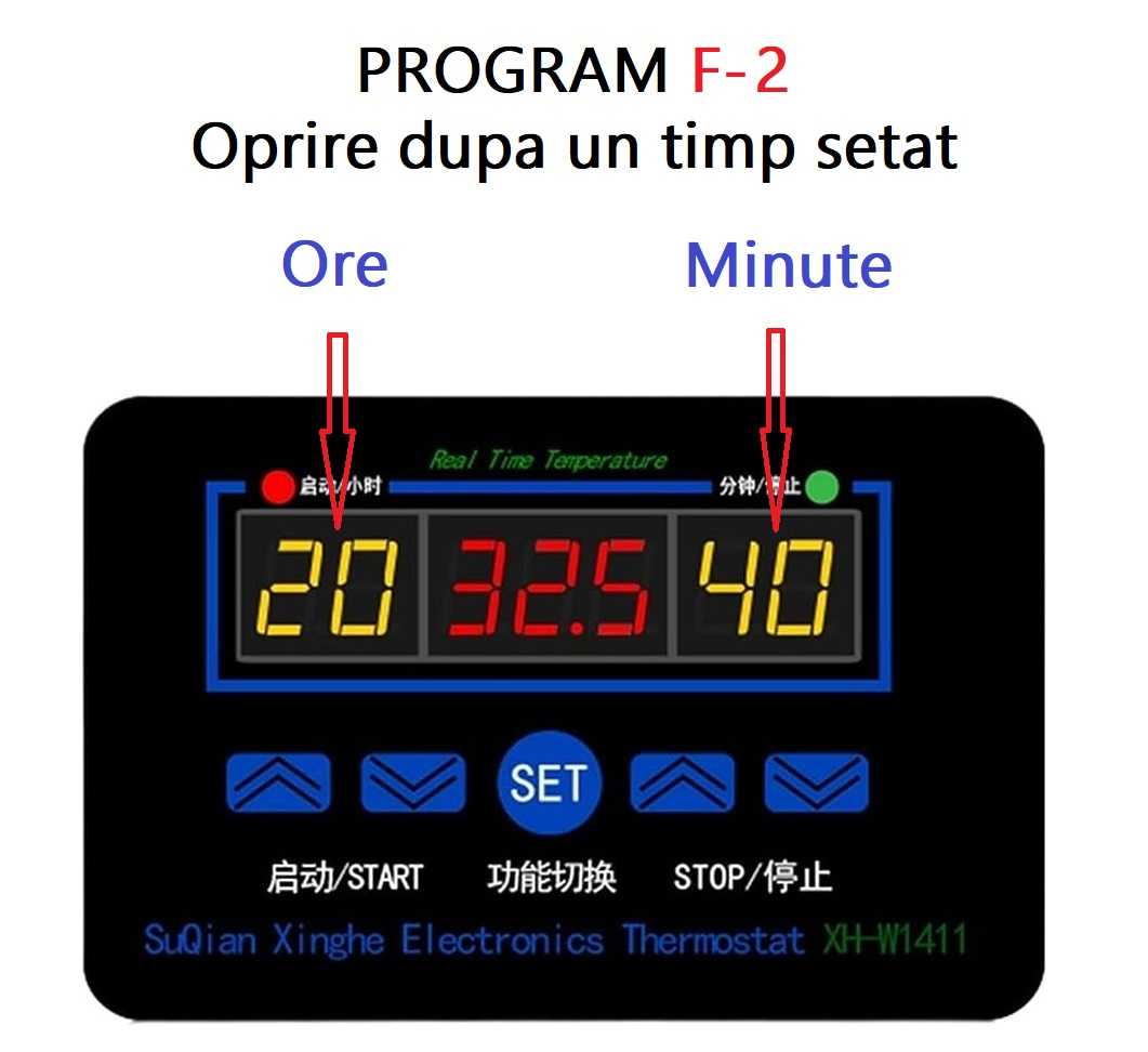
In F-3 mode, set the hours with the left buttons and the minutes with the right buttons, up to 99 hours and 99 minutes.
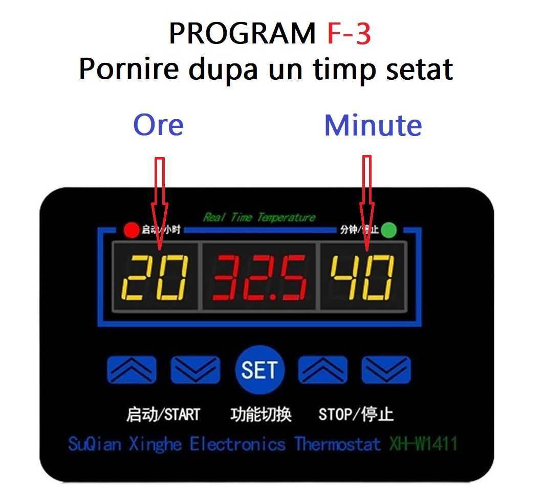
To stop, hold the SET button for a few seconds. A short press on any button starts the module again.
To calibrate, leave the module unpowered, hold down the SET button, and power on the module. 0.0 is shown in the middle of the screen. Immediately compensate, with the left buttons, for the difference between the displayed temperature and the actual temperature, with plus or minus. After a few seconds of inactivity the module exits calibration.
For self-diagnosis, leave the module unpowered, hold down the UP and DOWN arrows on the left simultaneously, and power on the module with the buttons held down until the beep ends.
To restore factory settings, leave the module unpowered, hold down the UP and DOWN arrows on the right simultaneously, and power on the module with the buttons held down. 88-888-88 appears in the middle, and the buttons must be held until the beep ends.
For stable results, secure the probe properly, use conductors with a cross-section suitable for the load current, and do not use the module in humid environments or outdoors.
- Input Voltage
- Input Voltage Type
- AC
Produs destinat utilizarii in proiecte electronice, automatizari, prototipare, educatie si cercetare.
Produsul trebuie utilizat numai conform specificatiilor tehnice mentionate in descriere si/sau in documentatia produsului.
Avertismente generale de siguranta:
Nu utilizati produsul la tensiuni, curenti sau temperaturi peste valorile specificate.
Montajul si conectarea trebuie realizate de persoane cu cunostinte tehnice minime in domeniul electric/electronic.
Evitati scurtcircuitele, inversarea polaritatii si conectarea gresita a alimentarii.
Nu lasati produsul alimentat nesupravegheat in timpul testelor.
Produsul nu este jucarie si nu este destinat copiilor.
Pentru modulele electronice, se recomanda utilizarea in carcase, panouri sau montaje protejate, dupa caz.
Identificare produs:
Denumirea produsului, codul/SKU-ul si caracteristicile tehnice sunt mentionate in pagina produsului si/sau pe eticheta ambalajului.
Producator / Importator / Distribuitor:
Sigmanortec S.R.L.
Calea Bucuresti nr. 9, Targu Jiu, Gorj, Romania
E-mail: [email protected]
Website: www.sigmanortec.ro
Persoana responsabila in UE:
Sigmanortec S.R.L.
Calea Bucuresti nr. 9, Targu Jiu, Gorj, Romania
E-mail: [email protected]
Documentatie si siguranta:
Pentru informatii suplimentare, fise tehnice, declaratii de conformitate sau instructiuni, ne puteti contacta la [email protected].
Reviews (1) - Review moderation

I used it to monitor the temperature of a domestic hot water tank (water heater (RO: boiler)). This thermostat controls a solid fuel (pellet) boiler (RO: centrala pe peleti) that can be turned on or off using a dry contact switch. I didn?t fully understand the instructions, unfortunately, the manual is only available in Chinese. If I search for the instruction manual on the Internet, I find this page (thanks to the authors). In the end, after several attempts and with the instructions from this page, I managed to understand and correctly configure the thermostat so that I can control the boiler based on the water temperature in the tank. For example, if I want the water temperature in the boiler to be around 42 degrees, I set the minimum value to 40 and the maximum value to 44. This way, if the water temperature in the boiler drops below 40 degrees, the thermostat commands the boiler to start heating, and when the water temperature reaches 44 degrees, the boiler stops. Due to thermal inertia, the system continues to cool the boiler, causing the water temperature in the tank to rise by a few more degrees. PS: Thank you very much for the candies included in the package ? my little boy really enjoys every order from this site!
This tutorial shows how to put the XH-W1411 (W88) 220 VAC thermostat module into operation. It is used exactly as it is, as a standalone module. The module has its own controller and is adjusted with buttons and a display, so you do not need a development board and no program is written.
Use it in projects where a mains load must be switched on and off according to temperature (reptile heating, incubator, greenhouse, cooling fan) or according to time (intermittent operation, scheduled switch-off or switch-on).

How it works:
The probe is a 10 kOhm NTC thermistor with a B coefficient of 3435. With an NTC, the resistance decreases as the temperature rises. Approximately, the resistance is calculated with the formula R = R0 x exp(B x (1/T - 1/T0)), where R0 is 10 kOhm at T0 = 298.15 K (25 °C), B is 3435, and the temperatures T are taken in kelvin. From the formula, this gives about 30.8 kOhm at 0 °C, 10 kOhm at 25 °C and 4.1 kOhm at 50 °C.
The controller measures this resistance, converts it to degrees Celsius with a resolution of 0.1 °C and compares the value with the two set thresholds, the switch-on temperature (the left display) and the switch-off temperature (the right display). The result drives a relay with contacts rated 250 VAC and 10 A.
In heating mode (switch-on lower than switch-off), the output activates when the temperature falls to the switch-on value and turns off when it reaches the switch-off value. In cooling mode (switch-on higher than switch-off), the output activates when the temperature rises to the switch-on value and turns off when it drops to the switch-off value. The difference between the two thresholds is the hysteresis, that is, the zone in which the relay does not switch, and it prevents the relay from chattering continuously around a single value.
The output is a normally open / normally closed contact, without a voltage of its own. The relay is connected in series with the load, on the live wire, and the load current is P / U. A 500 W heater at 220 V draws about 2.3 A, so it is well below the 10 A limit.
Wiring:
Caution, the module is powered from the 220 VAC mains and switches a 220 VAC load, which can cause a serious electric shock. Connections must be made only with the mains completely disconnected, by a qualified person. The metal parts of the load must be connected to the protective earth.
The module has two POWER wires (red and black) for supply, two yellow LOAD wires for the relay output and the NTC probe already attached, with a 1 metre cable. There are no logic levels, because the module does not communicate with other boards.
| Product pin | Connect to | Role |
|---|---|---|
| POWER (wire 1) | Mains live (L) | 220 VAC supply |
| POWER (wire 2) | Mains neutral (N) | 220 VAC supply |
| LOAD (yellow wire 1) | Mains live (L) | Relay contact input |
| LOAD (yellow wire 2) | Live wire of the load (heater) | Relay contact output, maximum 10 A |
| Load (second wire) | Mains neutral (N) | Return of the load current |
| NTC (black cable) | Attached, placed in the measuring zone | Temperature sensor |
Buttons, settings and indicators:
| Element | What it does | How to use it |
|---|---|---|
| Left display | Shows the switch-on temperature, the ON time in F-1 or the hours in F-2 and F-3. | Read the value set with the left buttons. |
| Middle display | Shows the current temperature or the mode F-1, F-2, F-3. | A current temperature in the middle means the module is working as a thermostat. |
| Right display | Shows the switch-off temperature, the OFF time in F-1 or the minutes in F-2 and F-3. | Read the value set with the right buttons. |
| Red LED | Relay ON, the LOAD output is active. | Lights up when the load is powered. |
| Green LED | Relay OFF, the LOAD output is stopped. | Lights up when the load is not powered. |
| Left UP / DOWN buttons | Adjust the switch-on temperature, the ON time in F-1 or the hours in F-2 and F-3. | UP increases the value, DOWN decreases it. Pressed at power-up, they activate the self-diagnosis. In calibration they compensate the displayed temperature. |
| SET button | Selects the functions F-1, F-2, F-3, turns the module on / off and enters calibration. | Short press for functions, long press of a few seconds for switching off, pressed at power-up for calibration. |
| Right UP / DOWN buttons | Adjust the switch-off temperature, the OFF time in F-1 or the minutes in F-2 and F-3. | UP increases the value, DOWN decreases it. Pressed at power-up, they restore the factory settings. |
Setting the switch-on temperature: with the module powered and the current temperature in the middle, press the left UP / DOWN buttons until the left display shows the desired value. The value remains in memory when the power is cut.
Setting the switch-off temperature: press the right UP / DOWN buttons until the right display shows the desired value. If the switch-on is lower than the switch-off, the module heats. If the switch-on is higher than the switch-off, the module cools.
Checking the setting: the red LED lights when the output is active, and the green LED when it is off. For heating, the red LED must be on when the temperature is below the switch-on value.
Switching the module off and on: keep SET pressed for a few seconds to switch off, then briefly press any button to switch on.
Configuration:
| Mode | Middle display | Left display | Right display |
|---|---|---|---|
| Thermostat (normal) | Current temperature | Switch-on temperature | Switch-off temperature |
| F-1 intermittent operation | F-1 | ON time, 1 - 99 minutes | OFF time, 1 - 99 minutes |
| F-2 scheduled switch-off | F-2 | Hours | Minutes |
| F-3 scheduled switch-on | F-3 | Hours | Minutes |
Step 1, thermostat: power the module, set the switch-on with the left buttons and the switch-off with the right buttons, following the heating or cooling rule above.
Step 2, time functions: briefly press SET to move to F-1, F-2 or F-3. The middle display shows the active mode, and the values are adjusted with the left and right buttons. The functions do not work together, so in F-1 the module no longer works as a thermostat and vice versa. To return to the thermostat, press SET until the current temperature appears again in the middle.
Step 3, calibration: with the module unpowered, keep SET pressed and power the module. The middle of the screen shows 0.0. Compensate, with the left buttons, plus or minus, the difference between the displayed temperature and the one measured with a reference thermometer. After a few seconds of inactivity the module exits calibration by itself. The displayed temperature becomes the measured temperature plus the calibration value.
Step 4, self-diagnosis: with the module unpowered, keep the left UP and DOWN buttons pressed at the same time and power it. Keep them pressed until the beeping signal ends.
Step 5, reset: with the module unpowered, keep the right UP and DOWN buttons pressed at the same time and power it. 88-888-88 appears in the middle. Keep pressing until the beeping signal ends. The settings return to the factory values.
All settings are kept in memory and remain after a power interruption.
Usage example:
Goal: keep an enclosed space between 25 °C and 28 °C with a 220 VAC and 500 W ceramic PTC heater.
Step 1: with the mains completely disconnected, connect the POWER wires to L and N, one yellow LOAD wire to L, the other yellow wire to the live wire of the heater, and the second heater wire to N. The heater draws about 2.3 A, so it is within the 10 A limit. If the heater has a metal casing, connect its protective earth too.
Step 2: place the probe in the space to be controlled, at a distance from the heater, so that it measures the air temperature and not the radiated heat.
Step 3: power the module. The current temperature, for example 21.5, must appear in the middle.
Step 4: set the switch-on to 25 with the left buttons and the switch-off to 28 with the right buttons. Since the switch-on is lower than the switch-off, the module works in heating mode.
Step 5: watch the LEDs. While the temperature is below 25 °C, the red LED is on and the heater works. When the temperature reaches 28 °C, the relay turns off and the green LED lights up. The heater will restart when the temperature falls to 25 °C again.
Timed variant: for intermittent operation, press SET until F-1 appears, set 1 minute ON with the left buttons and 3 minutes OFF with the right buttons. The load will work for one minute and stay off for three minutes, in a cycle, regardless of the temperature.
Common problems:
The display stays off even though the module is powered. The most likely cause is that the module was switched off with the SET button. Briefly press any button to switch it on. If it stays off, check with the module disconnected the POWER wire connections and the presence of voltage at the socket.
The load does not start, even though the red LED is on. The cause is in the load circuit. Check that the yellow LOAD wires are in series with the load, and that the load has its neutral connected.
The module works the opposite way from what it should, for example it cools instead of heating. The cause is the switch-on and switch-off values being reversed. For heating, the switch-on must be lower than the switch-off, and for cooling the reverse.
The module does not react to temperature. A possible cause is that one of the modes F-1, F-2 or F-3 is selected, which do not work together with the thermostat. Press SET until the current temperature is shown in the middle.
The displayed temperature differs from the real one. The cause is the tolerance of the probe or its position. Check the placement of the probe, then calibrate with a reference thermometer.
The settings seem incorrect or the module behaves unusually. The cause may be a wrong setting. Reset to the factory values, with the right UP and DOWN buttons pressed at power-up.
Limitations and tips:
The module measures between -50 °C and 110 °C, and the switch-on and switch-off temperatures can be set between -19 °C and 99 °C, with a resolution of 0.1 °C. The control is of the On/Off type, without proportional adjustment.
The relay contacts withstand a maximum of 10 A at 250 VAC. For larger or inductive loads (motors, compressors), use an intermediate contactor controlled by the module. The module itself is not waterproof, so mount it away from moisture.
You can use it further for the automatic control of a cooling fan, a pump or an aquarium heater, and the functions F-1, F-2 and F-3 can replace a simple timer relay.