
Product images are for informational purposes only and may vary slightly depending on the batch and supplier. Product specifications and prices may be subject to change without notice. We do our best to provide accurate and complete product specifications, but they may not be completely accurate. If you encounter any such situation, please let us know.
The product is intended for specialists and requires qualified and authorized personnel. The product does not include assembly/use instructions . Putting the product into operation by unqualified persons leads to the loss of the warranty according to the Terms and Conditions on the site.
The specified technical parameters (current, power, etc.) represent maximum allowable values under ideal operating conditions. For safe use and optimal lifespan, it is recommended to operate the product continuously at no more than 50% of the specified maximum values.
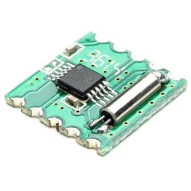
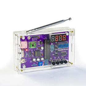
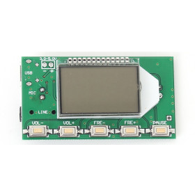
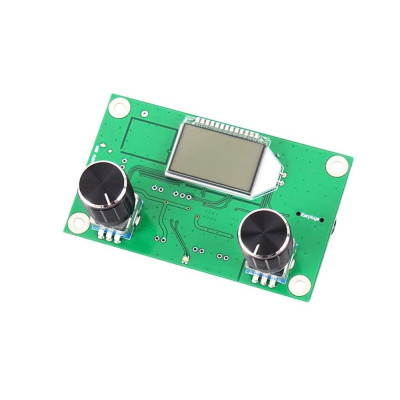
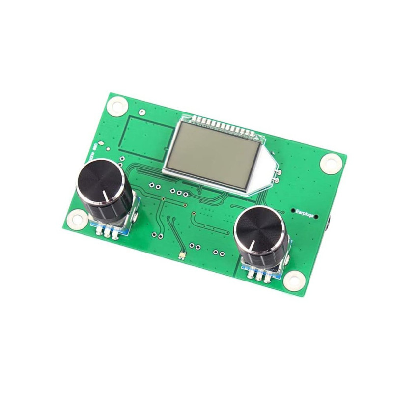
FM DSP PLL radio receiver module, 87–108 MHz with LCD, Campus mode 76–108 MHz, stereo output 2x3W
FM stereo radio receiver module with DSP and PLL, LCD display and two rotary encoders VOL and FRE for volume and tuning, ideal for active speakers, wireless microphones, school public address systems and DIY projects. It covers the standard 87.0 - 108.0 MHz band, extendable to 76.0 - 108.0 MHz in Campus mode for university stations, with 500 mW stereo audio output on headphones or 2x3 W on speakers, UART serial control and automatic settings memory.
Shipping by Thursday 22 October
Buying this product earns you 0.77 € in loyalty points.

International fast shipping within EU. Free Shipping for orders above 100 EUR in most EU countries.

We ship from our stock within 24H

You earn points with every order, worth 5%.
The FM radio receiver module combines a DSP circuit (digital audio signal processing) with a PLL synthesizer, designed as a complete receiver block for active speakers, school PA systems, wireless microphones with dedicated receivers, DIY bench radios, or audio monitoring stations. The board has its own controller, LCD display, and two rotary encoders, so it operates independently without requiring an external development board for basic use.
Reception covers the standard 87.0 - 108.0 MHz band, and by enabling Campus Mode the band extends to 76.0 - 108.0 MHz, for university radio stations broadcasting below the lower limit of the commercial band. Tuning is done with the FRE encoder, and volume with the VOL encoder, both with push action for additional functions (mute/unmute on VOL, automatic squelch on/off on FRE). The digital squelch is adjustable in 20 steps, and the volume in 30 steps, both shown on the LCD. The module also supports control via UART TTL serial communication, with dedicated AT commands for frequency, volume, campus mode, and squelch threshold.
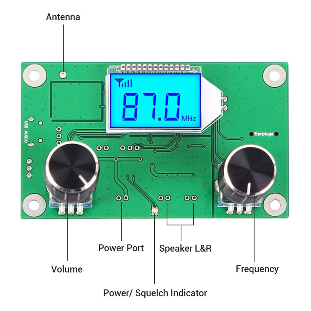
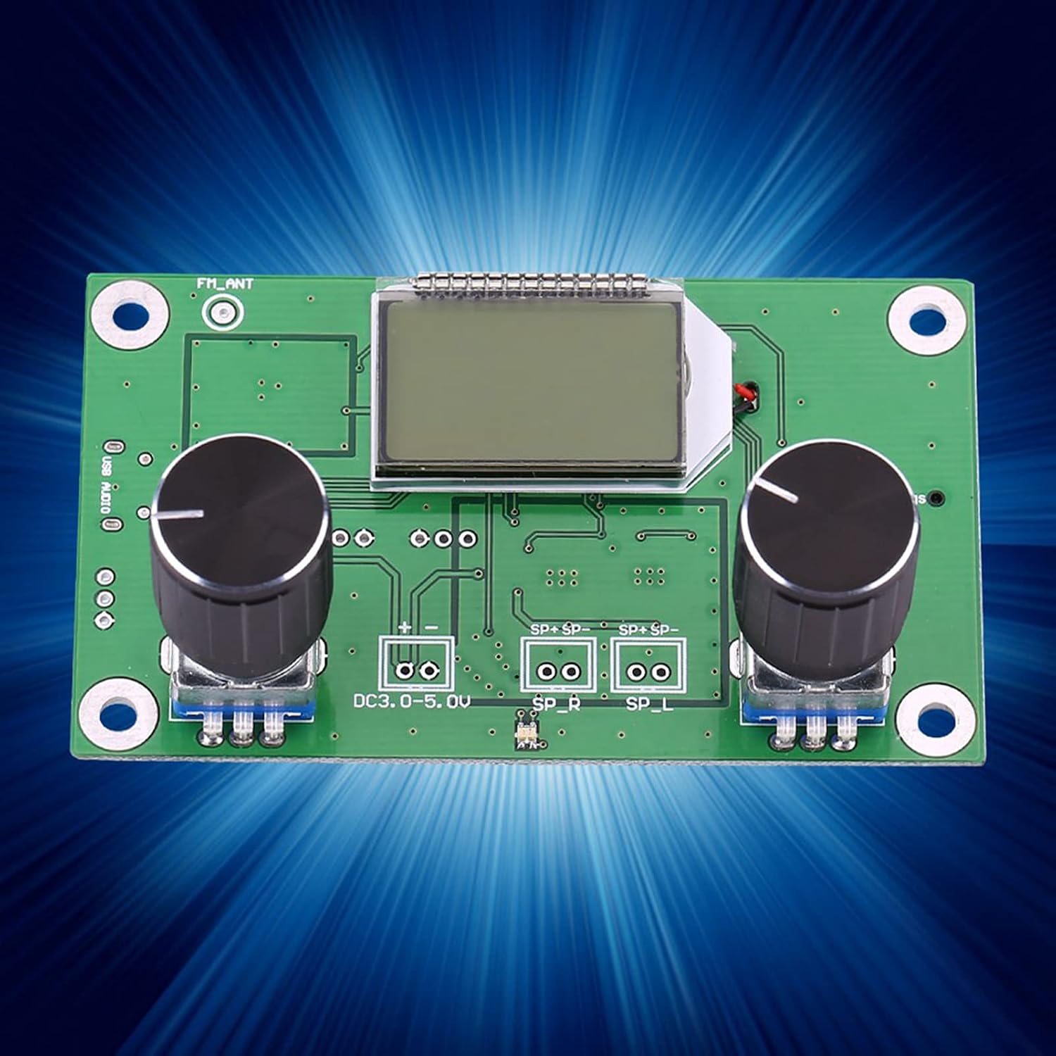
Among the main features are the DC3.0-5.0V power terminal with + and - pins, the SP_R and SP_L pin pairs for the two speaker channels, the FM_ANT pad for an external antenna, the Earplugs jack with automatic headphone/speaker switching, the LCD display with adjustable backlight, and the two VOL and FRE encoders. Power is supplied at 3.0 - 5.0 VDC through the DC3.0-5.0V terminal, recommended from a battery or a stabilized and filtered supply, not from a phone charger or another unfiltered switching supply, because its noise affects reception.
Through the UART TTL serial interface, the module can be controlled by a microcontroller or a computer (via a USB-TTL adapter), being compatible with Arduino, ESP32, STM32, or Raspberry Pi for automating tuning, volume, and Campus mode.
Specifications:
Supply voltage: 3.0 - 5.0 VDC
Current consumption: under 50 mA at minimum volume, up to 400 mA at maximum volume
Type: Stereo FM receiver module with DSP and PLL
Frequency band (Campus off): 87.0 - 108.0 MHz
Frequency band (Campus on): 76.0 - 108.0 MHz
Audio frequency response: 50 Hz - 18 kHz
Audio output power: 500 mW for headphones, 2 x 3 W for speakers
Signal-to-noise ratio: minimum 30 dB
Volume: 30 digital steps, adjustable from the VOL encoder
Serial communication: UART TTL, 38400 bps, AT commands for frequency, volume, campus mode, and squelch threshold
Display: LCD showing frequency, volume, stereo/mono, Campus mode, and adjustable backlight
Antenna: FM_ANT pad for external antenna, recommended 75 cm whip
Integrated functions: station search and memory, automatic settings save on power loss, automatic headphone/speaker switching, digital squelch adjustable in 20 steps
Dimensions: 80 x 50 mm
Layout:
| Element | Function |
|---|---|
| FM_ANT | Pad for the external FM antenna, recommended 75 cm whip. |
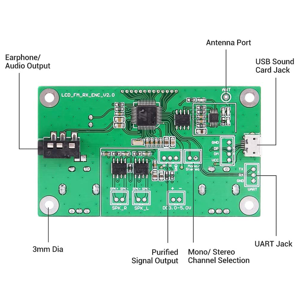
| USB AUDIO | Pins marked on the board, reserved for an optional USB audio interface, depending on the board version. |
| DC3.0-5.0V (+, -) | Module power terminal, 3.0 - 5.0 VDC. |
| SP_R (SP+, SP-) | Audio output for the right speaker channel. |
| SP_L (SP+, SP-) | Audio output for the left speaker channel. |
| Encoder FRE | Reception frequency adjustment, short press to turn automatic squelch on/off, press to enter squelch threshold adjustment. |
| Encoder VOL | Volume adjustment in 30 steps, short press for mute/unmute, long press while off to switch Campus mode. |
| LCD display | Displays frequency, volume, stereo/mono status, Campus mode (C0/C1), and backlight status (B0/B1). |
| Earplugs jack | Headphone output, with automatic switching of the amplifier from speakers to headphones when connected. |
| Mounting holes | 4 holes for fixing the board. |
Pinout:
| Connector | Pin | Function |
|---|---|---|
| DC3.0-5.0V | + | Positive power supply, 3.0 - 5.0 VDC |
| DC3.0-5.0V | - | Negative power supply, ground |
| SP_R | SP+ | Right channel audio output, positive |
| SP_R | SP- | Right channel audio output, negative |
| SP_L | SP+ | Left channel audio output, positive |
| SP_L | SP- | Left channel audio output, negative |
| FM_ANT | - | Pad for the external FM antenna (recommended 75 cm whip) |
| USB AUDIO | - | Reserved pins for the optional USB audio interface |
| UART | TX, RX, GND | TTL serial access for external control (AT commands), 38400 bps |
| LCD command | Status |
|---|---|
| C0 | Campus mode disabled, band 87.0 - 108.0 MHz |
| C1 | Campus mode enabled, band 76.0 - 108.0 MHz |
| B0 | LCD backlight turns off automatically after a set interval |
| B1 | LCD backlight stays on permanently |
Usage:
Connect the power supply to the + and - pins of the DC3.0-5.0V terminal, observing polarity and using a voltage between 3.0 and 5.0 VDC.
Power the module from a battery or from a stabilized and filtered supply, not from a phone charger or another unfiltered switching supply, because its noise is introduced into reception.
Connect 4 ohm / 3 W speakers to the SP_R and SP_L pin pairs, or connect headphones to the Earplugs jack, in which case the speaker output stops automatically.
Attach an external antenna to the FM_ANT pad, preferably a 75 cm whip, positioned away from sources of electrical noise.
Turn the FRE encoder to tune the desired frequency and the VOL encoder to adjust the volume, following the values shown on the LCD.
To listen to university radio stations outside the commercial band, turn the module off, long-press the VOL encoder until the LCD shows C1, then turn the module back on for the extended 76.0 - 108.0 MHz band to become active.
To return to the standard band, repeat the shutdown procedure and long-press the VOL encoder until the LCD shows C0.
Short-press the FRE encoder to turn automatic squelch on or off, and when it is active, press again to enter squelch threshold adjustment (0-20) and rotate the encoder to the desired value.
For control from a microcontroller or computer, connect the UART pins marked on the board (TX, RX, GND) to a USB-TTL adapter or to the serial port of an MCU, using TTL level and 38400 bps speed, then send AT commands for frequency, volume, or Campus mode.
Do not exceed the 5.0 VDC supply voltage and do not reverse polarity, to avoid damaging the module.
- Frequency band
- 87 - 108 MHz
- Circuit technology
- DSP PLL
- Module function
- Receptor FM
Produs destinat utilizarii in proiecte electronice, automatizari, prototipare, educatie si cercetare.
Produsul trebuie utilizat numai conform specificatiilor tehnice mentionate in descriere si/sau in documentatia produsului.
Avertismente generale de siguranta:
Nu utilizati produsul la tensiuni, curenti sau temperaturi peste valorile specificate.
Montajul si conectarea trebuie realizate de persoane cu cunostinte tehnice minime in domeniul electric/electronic.
Evitati scurtcircuitele, inversarea polaritatii si conectarea gresita a alimentarii.
Nu lasati produsul alimentat nesupravegheat in timpul testelor.
Produsul nu este jucarie si nu este destinat copiilor.
Pentru modulele electronice, se recomanda utilizarea in carcase, panouri sau montaje protejate, dupa caz.
Identificare produs:
Denumirea produsului, codul/SKU-ul si caracteristicile tehnice sunt mentionate in pagina produsului si/sau pe eticheta ambalajului.
Producator / Importator / Distribuitor:
Sigmanortec S.R.L.
Calea Bucuresti nr. 9, Targu Jiu, Gorj, Romania
E-mail: [email protected]
Website: www.sigmanortec.ro
Persoana responsabila in UE:
Sigmanortec S.R.L.
Calea Bucuresti nr. 9, Targu Jiu, Gorj, Romania
E-mail: [email protected]
Documentatie si siguranta:
Pentru informatii suplimentare, fise tehnice, declaratii de conformitate sau instructiuni, ne puteti contacta la [email protected].
This tutorial uses the FM radio receiver module DSP PLL, 87-108 MHz, with LCD and stereo output 2x3 W, together with the FM radio transmitter module DSP PLL with LCD. We do not use any development board or program, because both modules have their own controller, their own LCD display and their own commands and work independently, each powered by a battery holder.
The receiver has an integrated stereo amplifier and can play directly on two 4 ohm speakers. The transmitter sends audio from a phone, from a computer or from its own microphone into the air. Together they form a wireless audio link over short distances. They can be used for a wireless speaker, a wireless microphone, a camera monitor or for sound reinforcement in a classroom.
How it works:
The transmitter receives the audio signal, processes it digitally with the DSP circuit and modulates it in frequency (FM) at a frequency you choose. The PLL synthesizer keeps the frequency stable, without drifting with temperature or over time. The transmit power is 100 mW, and the transmitted audio band is 50 Hz - 18 kHz.
The receiver does the reverse. The antenna brings in the FM signal, the DSP circuit demodulates and decodes it stereo, and the integrated amplifier delivers 2 x 3 W to 4 ohm speakers or 500 mW to headphones. A digital squelch, adjustable in 20 steps, cuts the sound when the signal is too weak, so you don't hear the background hiss between stations.
The frequency is adjusted in 0.1 MHz steps. In the standard band 87.0 - 108.0 MHz there are (108.0 - 87.0) / 0.1 + 1 = 211 possible frequencies. With Campus mode enabled the band becomes 76.0 - 108.0 MHz, that is (108.0 - 76.0) / 0.1 + 1 = 321 frequencies. The transmitter and receiver must have the same frequency and the same band setting (C0 or C1), otherwise they won't communicate.
The Campus setting matters even if the chosen frequency is in the standard band. One module with C0 and one with C1 are not configured the same way, so for the first test set C0 on both modules, and choose the frequency between 87.0 and 108.0 MHz.
Connection:
Each module has its own 3 x AA battery holder, which provides 4.5 V, within the allowed range of 3.0 - 5.0 VDC. Batteries are a good choice because they don't introduce switching noise in reception. Do not use phone chargers or other unfiltered switching power sources. Do not exceed 5.0 V and respect the polarity. For the receiver choose a power source that can provide at least 1 A, because at high volume with speakers the current consumption increases significantly. The audio connections of the modules do not use logic levels, so there is no need for a level converter, resistors or separate signal power.
| Product pin | Connects to | Role |
|---|---|---|
| Receiver + (DC 3.0-5.0 V terminal) | Plus of the receiver 3 x AA battery holder | Power supply 3.0 - 5.0 VDC |
| Receiver - (DC 3.0-5.0 V terminal) | Minus of the receiver 3 x AA battery holder | Ground |
| Receiver FM_ANT | 75 cm FM telescopic antenna | Antenna input |
| Receiver SP_R (SP+ and SP-) | Right speaker 4 ohms / 3 W (plus on SP+, minus on SP-) | Right channel audio output |
| Receiver SP_L (SP+ and SP-) | Left speaker 4 ohms / 3 W (plus on SP+, minus on SP-) | Left channel audio output |
| Transmitter + | Plus of the transmitter 3 x AA battery holder | Power supply 3.0 - 5.0 VDC |
| Transmitter - | Minus of the transmitter 3 x AA battery holder | Ground |
| Transmitter ANT | 75 cm FM telescopic antenna | Antenna output |
| Transmitter LINE (3.5 mm jack) | 3.5 mm audio output of the phone, through a jack cable | Stereo audio input |
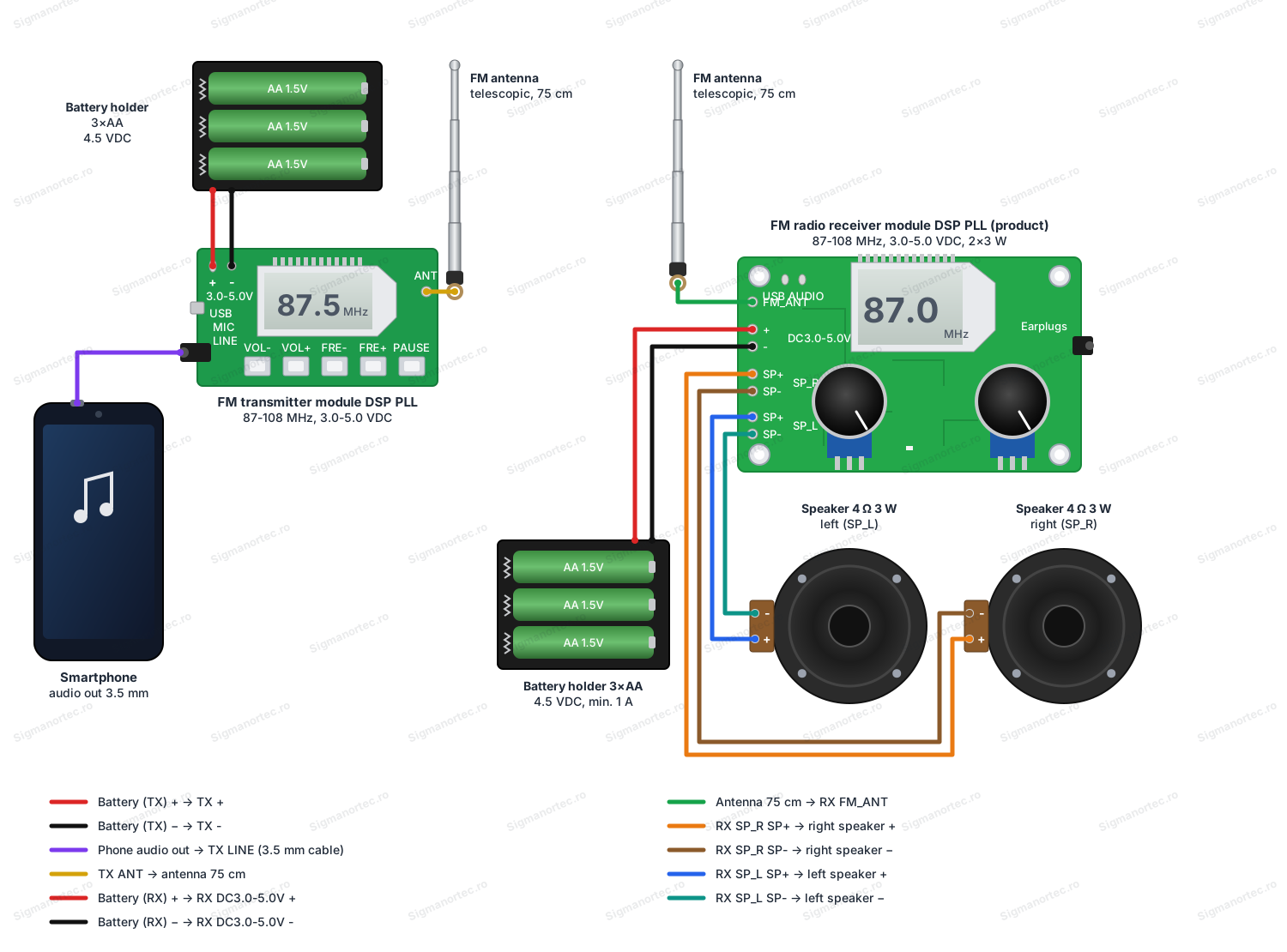
Do not connect the receiver's SP- pins to ground and do not link them to each other. The speaker outputs are in bridge mode, and an SP- connected to ground can damage the amplifier. Each speaker uses both pins of its pair, SP+ and SP-. Check the pad names on the board silkscreen before soldering, because the order in the diagram may differ slightly from that on the board.
Configuration:
The receiver is controlled from two rotary encoders with a button, marked FRE and VOL. The settings are automatically saved when power is disconnected, so at the next startup the module returns to the same frequency, with the same volume and the same options. The table below lists the receiver actions.
| Action | Effect on receiver |
|---|---|
| Rotate FRE encoder | Changes frequency, value appears on LCD |
| Rotate VOL encoder | Changes volume in 30 steps, value appears on LCD |
| Short press VOL encoder | Mute / unmute |
| Short press FRE encoder | Turns automatic squelch on or off |
| Press FRE encoder with squelch active | Enters squelch threshold adjustment, 0 - 20, adjust by rotating FRE |
| Long press VOL at startup | Switches Campus mode, LCD shows C0 (87.0 - 108.0 MHz) or C1 (76.0 - 108.0 MHz) |
| Long press FRE at startup | Switches backlight, B0 turns off after a timeout, B1 stays on |
To change the Campus mode on the receiver, disconnect power, press and hold the VOL encoder, reconnect power and wait for C0 or C1 to appear on the LCD. Repeat the procedure to return to the previous value. The setting takes effect on restart. The backlight is switched the same way, with the FRE encoder.
The transmitter is controlled from buttons, and the table below shows their functions.
| Action | Effect on transmitter |
|---|---|
| VOL+ and VOL- | Increase or decrease volume, held down repeats steps |
| FRE+ and FRE- | Change frequency by 0.1 MHz on short press, by 1 MHz on long press |
| PAUSE | Mute / unmute |
| VOL+ and VOL- held down at startup | Switches Campus mode, C0 or C1 on LCD |
The transmitter automatically selects its audio source. A cable in the 3.5 mm LINE jack provides stereo input. A USB cable to a computer turns it into a sound card named CD002, the LCD shows PC and the module is powered from USB. Without either of them it uses its own microphone, in mono.
Usage example:
We will transmit music from a phone to a stereo speaker, on frequency 87.5 MHz, with Campus mode off on both modules.
Insert the batteries into the two holders, but don't power up the transmitter yet. Power up the receiver and check that the LCD shows C0. Rotate the FRE encoder and look for a free frequency, that is one where you hear only background noise. If 87.5 MHz is occupied by a local station, choose another free frequency and use it instead throughout the example.
Power up the transmitter and check that the LCD shows C0. Press FRE+ or FRE- until 87.5 MHz appears on the display. Connect the phone to the LINE jack with a 3.5 mm jack cable and start playing music, with the phone volume at approximately three quarters.
On the receiver, tune to 87.5 MHz with the FRE encoder and increase the volume with the VOL encoder to approximately 15 out of 30. After a few seconds the music should be heard on both speakers, and the receiver's LCD should indicate stereo reception.
Then adjust the final volume from the VOL encoder on the receiver. Adjust the transmitter volume only if the sound is distorted or too low. For the first test keep the modules a few meters apart from each other, then gradually move them away to see how far the clean reception goes.
Frequent problems:
A humming or crackling sound is heard from the speakers. The usual cause is power from a phone charger or another unfiltered switching source, whose noise passes through to reception. Switch to batteries or a stabilized and filtered power source.
The receiver produces no sound, even though the transmitter is transmitting. First check that the frequency and C0 or C1 setting are the same on both modules. Then check that there is no headphone jack in the Earplugs jack, because the speaker output automatically turns off, and the sound is not muted. If squelch is active, lower the threshold or turn it off, because a high threshold cuts weak signals.
The sound distorts or the module resets when you turn up the volume. The power source cannot provide the current required by the amplifier at high volume. Use fresh batteries or a source that can provide at least 1 A and lower the volume.
One speaker is not working or the amplifier gets hot. Check that both pins of each SP_R and SP_L pair are connected only to their speaker and that no SP- touches ground or another SP-. Use 4 ohm speakers, not lower impedance ones.
Reception is weak or there is a lot of noise. Fully extend the 75 cm telescopic antennas on both modules and move them away from cables, switching sources or other electronic devices. Increase the distance between the two modules only if reception is saturated at very close distances.
The backlight turns off by itself. This is normal behavior in B0 mode. For permanent light, switch to B1 with the procedure in the Configuration section, then restart the module.
Limitations and tips:
FM transmission has 100 mW and a range of tens of meters in open field, smaller in buildings with thick walls. The quality is suitable for music and voice, but not for high fidelity playback, with an audio band of 50 Hz - 18 kHz and a signal to noise ratio of at least 30 dB. Choose a free frequency and comply with local radio transmission regulations.
The receiver amplifier delivers 2 x 3 W to 4 ohm speakers and 500 mW to headphones. For a more powerful speaker, use the headphone output as a signal source for an external amplifier.
The receiver also has a serial UART interface at TTL level, with TX, RX and GND pads, speed of 38400 bps and AT commands for frequency, volume, Campus mode and squelch threshold. You can use it with a microcontroller or with a USB-TTL adapter, for example Arduino, ESP32, STM32 or Raspberry Pi, if you want to automate tuning. Check the logic level of the board you are connecting to, because the module's interface is TTL.
For a transmitter that runs continuously, power it from USB from a computer or from a good power adapter, and for the portable receiver use batteries. For a wireless microphone, leave the transmitter without a LINE cable and without USB, so it uses its own microphone, and adjust the volume for clear sound.