
Product images are for informational purposes only and may vary slightly depending on the batch and supplier. Product specifications and prices may be subject to change without notice. We do our best to provide accurate and complete product specifications, but they may not be completely accurate. If you encounter any such situation, please let us know.
The product is intended for specialists and requires qualified and authorized personnel. The product does not include assembly/use instructions . Putting the product into operation by unqualified persons leads to the loss of the warranty according to the Terms and Conditions on the site.
The specified technical parameters (current, power, etc.) represent maximum allowable values under ideal operating conditions. For safe use and optimal lifespan, it is recommended to operate the product continuously at no more than 50% of the specified maximum values.
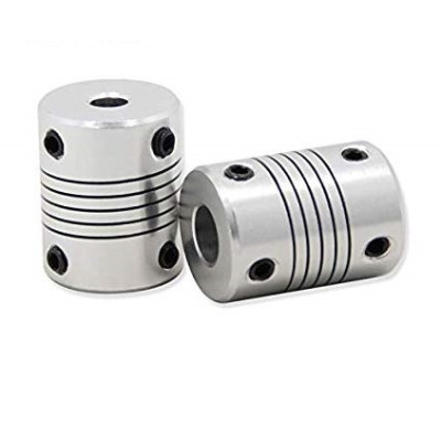
Flexible Coupling 5mm*8mm, Aluminum, D19 x L25mm
Ensures a secure connection between two shafts with different diameters, ideal for precision transmissions in CNC, 3D printers or automation. Compensates small misalignments and reduces vibrations, mounts quickly on 5mm and 8mm shafts, has a compact construction with a length of 25mm for tight spaces and helps protect the gear components.
Buying this product earns you 0.34 RON in loyalty points.

International fast shipping within EU. Free Shipping for orders above 100 EUR in most EU countries.

We ship from our stock within 24H

You earn points with every order, worth 5%.
The aluminum flexible coupling connects two shafts with different diameters, one of 5 mm and one of 8 mm, and transmits the rotary motion from one shaft to the other. It is suitable for connecting a stepper motor to a lead screw or an 8 mm shaft, in 3D printers, CNC machines, linear mechanisms and other mechanical assemblies with light to medium loads.
The coupling body has helical cuts along its length, which form a spring-like elastic element in the central area. The part remains rigid in torsion and transmits rotation without backlash, and through the flexibility of the body it absorbs small shaft misalignments (radial, angular and axial), reducing vibrations and the stress on the bearings. The bores are 5 mm at one end and 8 mm at the other, and the total length is 25 mm, with an outer diameter of 19 mm.
The main features include the single-piece aluminum body, the two bores of different diameters and two hex socket set screws at each end. The coupling has no electrical connections and requires no power supply, being mounted exclusively mechanically, by tightening the screws on the shafts.
Specifications:
Type: Flexible coupling with helical cuts
Material: Aluminum
Shaft diameter 1: 5 mm
Shaft diameter 2: 8 mm
Fixing: Hex socket set screws, 2 at each end
Length: 25 mm
Outer diameter: 19 mm
Dimensions: 19 x 25 mm
Layout:
| Element | Function |
|---|---|
| End with 5 mm bore | Receives the 5 mm shaft, for example the shaft of a stepper motor. |
| End with 8 mm bore | Receives the 8 mm shaft, for example a lead screw or a guide shaft. |
| Hex socket set screws, 5 mm end | Two screws that clamp the end onto the 5 mm shaft. They are tightened with a suitable hex key, after the shaft has entered the bore. |
| Hex socket set screws, 8 mm end | Two screws that clamp the end onto the 8 mm shaft. They are tightened with a suitable hex key, after the shaft has entered the bore. |
| Area with helical cuts | Provides the flexibility of the coupling and absorbs small misalignments and vibrations. It is not fixed and not actuated. |
Usage:
Before mounting, check the diameters of the two shafts, for example with a caliper, and choose the right end for each: the end with the smaller bore for the 5 mm shaft and the one with the larger bore for the 8 mm shaft.
Disconnect the motor or the mechanism you are working on from the power supply, so that the shaft cannot start accidentally.
Clean the shafts of oil and chips, then loosen the screws until they no longer protrude into the bores. Do not force the shaft into the coupling.
First mount the coupling on the motor shaft, leaving a small gap between the motor face and the coupling. Tighten the first screw lightly, then the second, then return to the first and tighten each one firmly.
Then insert the other shaft into the opposite end, leaving a small gap between the ends of the two shafts so that they do not touch inside the coupling. Align the shafts as well as possible and tighten the screws in the same alternating order.
Slowly rotate the assembly by hand. The mounting is correct if the two shafts turn together, without backlash, and the shafts do not slip in the coupling during a light hand test.
Do not exceed the small misalignments the coupling can absorb, and do not use it to compensate for an incorrect mounting.
For stable results, periodically check the tightness of the screws, especially on mechanisms with vibrations, and make sure the cut area is not deformed.
- Dimensions
- 19 x 25 mm
- Material
- Aluminium
- Type
- Flexible coupling with helical cuts
- Length
- 25 mm
- Outer diameter
- 19 mm
Produs destinat utilizarii in proiecte electronice, automatizari, prototipare, educatie si cercetare.
Produsul trebuie utilizat numai conform specificatiilor tehnice mentionate in descriere si/sau in documentatia produsului.
Avertismente generale de siguranta:
Nu utilizati produsul la tensiuni, curenti sau temperaturi peste valorile specificate.
Montajul si conectarea trebuie realizate de persoane cu cunostinte tehnice minime in domeniul electric/electronic.
Evitati scurtcircuitele, inversarea polaritatii si conectarea gresita a alimentarii.
Nu lasati produsul alimentat nesupravegheat in timpul testelor.
Produsul nu este jucarie si nu este destinat copiilor.
Pentru modulele electronice, se recomanda utilizarea in carcase, panouri sau montaje protejate, dupa caz.
Identificare produs:
Denumirea produsului, codul/SKU-ul si caracteristicile tehnice sunt mentionate in pagina produsului si/sau pe eticheta ambalajului.
Producator / Importator / Distribuitor:
Sigmanortec S.R.L.
Calea Bucuresti nr. 9, Targu Jiu, Gorj, Romania
E-mail: [email protected]
Website: www.sigmanortec.ro
Persoana responsabila in UE:
Sigmanortec S.R.L.
Calea Bucuresti nr. 9, Targu Jiu, Gorj, Romania
E-mail: [email protected]
Documentatie si siguranta:
Pentru informatii suplimentare, fise tehnice, declaratii de conformitate sau instructiuni, ne puteti contacta la [email protected].
Reviews (2) - Review moderation

cele mai bune preturi de pe piata,la acelasi nivel de calitate
Produsul este conform descrierii.
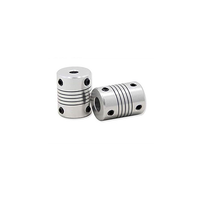
The 5 mm * 8 mm flexible coupling is an independent mechanical part, with no power supply, no program and no connections. It is an aluminium sleeve with an outer diameter of 19 mm and a length of 25 mm, with a 5 mm bore at one end and an 8 mm bore at the other.
It is used in mechanical projects to join two shafts with different diameters, for example the 5 mm shaft of a stepper motor and a trapezoidal lead screw or an 8 mm shaft, on a 3D printer, a CNC machine or a homemade linear mechanism. This tutorial shows how to choose the correct end, how to mount the part and how to check the assembly.
How it works:
The body of the coupling has several helical cuts along its length. They turn the central part into a spiral spring. The coupling remains rigid under torsion, so it transmits the rotational movement from one shaft to the other. On the other hand, it can bend and compress slightly, so it absorbs small misalignments between the shafts. Without it, a slightly offset shaft would load the bearings of the motor and of the screw, produce vibrations and wear the parts prematurely.
The coupling handles three types of small misalignment. Radial misalignment appears when the shafts are parallel but offset. Angular misalignment appears when the shafts form a small angle between them. Axial misalignment appears when the shafts move slightly along their length, for example due to thermal expansion. These misalignments must remain small. The coupling does not replace careful mounting, it only tolerates the small imperfections left after alignment.
A useful calculation for a mechanism with a stepper motor and a trapezoidal lead screw. The coupling transmits each step of the motor without modifying it, so the displacement remains determined by the lead of the screw. A screw with a lead of 8 mm per revolution and a motor with 200 steps per revolution give 8 / 200 = 0.04 mm per full step. With 1/16 microstepping, one obtains 0.04 / 16 = 0.0025 mm per microstep.
Connection:
The coupling has no electrical connections, logic level or supply voltage. It is mechanically mounted between two shafts, and the table shows what goes into each end. Before mounting, disconnect the motor from the power supply so that the shaft does not start accidentally.
| Product pin | Connects to | Role |
|---|---|---|
| 5 mm bore end | 5 mm shaft, for example the shaft of a stepper motor | Takes the rotation of the driving shaft |
| 8 mm bore end | 8 mm shaft, for example a trapezoidal lead screw or an 8 mm shaft | Transmits the rotation to the driven shaft |
| Helical cut zone | Not fixed to anything | Absorbs small alignment deviations and vibrations |
Buttons, adjustments and indicators:
The product has no buttons, potentiometers, jumpers, switches, LEDs or display. The only elements to operate are the hex socket clamping screws at the two ends, two at each end.
| Element | What it does | How to use it |
|---|---|---|
| Clamping screws, 5 mm end | Tighten the end of the coupling onto the 5 mm shaft | Tighten with a suitable hex key, after the shaft has fully entered the bore |
| Clamping screws, 8 mm end | Tighten the end of the coupling onto the 8 mm shaft | Tighten with a suitable hex key, after the shaft has fully entered the bore |
| Helical cuts | Provide the flexibility of the coupling | Do not operate. Only check that they are not deformed |
Fixing one end is done like this. Insert the shaft into the corresponding bore to the desired depth. Tighten the first screw lightly, then the second, then return to the first and tighten each one firmly. Alternate tightening keeps the shaft centred, and the screws do not loosen by themselves under vibration.
The starting position is with the screws loosened, so that the shafts enter the bores freely. After tightening, the adjustment is correct if the shaft no longer slips in the coupling when lightly tested by hand. When turning slowly by hand, the two shafts must rotate together, without play.
Configuration:
The coupling has no operating modes or electrical parameters. Configuration means the correct mechanical assembly. Follow the steps below in this order.
Identify the two ends. The end with the smaller bore fits on the 5 mm shaft, and the one with the larger bore on the 8 mm shaft. First check the shaft diameters, for example with a caliper. An undersized shaft is not held properly by the screws, and one that is too thick does not enter the bore.
Clean the shafts of oil and swarf. Loosen the screws until they no longer protrude into the bore. Do not force the shaft into the coupling, because under force it could enter deformed.
Mount the coupling on the motor shaft first. Leave a small gap between the motor face and the coupling, so that they do not rub. Tighten the screws of that end, alternating between them.
Then bring the driven shaft to the other end. Insert it into the bore and leave a small gap between the two shafts, so that they do not touch inside the coupling. Align the shafts as well as possible, then tighten the screws of the second end.
The assembly holds as long as the screws remain tight, so check them periodically.
Usage example:
Example from start to finish: connecting a stepper motor with a 5 mm shaft to a trapezoidal lead screw with a diameter of 8 mm, for the Z axis of a 3D printer.
Disconnect the motor power supply. Loosen all four screws of the coupling. Insert the 5 mm motor shaft into the small end of the coupling, leaving a few millimetres free from the motor face. Tighten the two screws of the 5 mm end, alternating between them.
Insert the trapezoidal lead screw into the 8 mm end. Leave a small gap between the ends of the two shafts. Fix the motor to the bracket without fully tightening its four screws. Turn the screw lightly by hand, then tighten the motor screws in the position where the rotation is smoothest.
Tighten the two screws of the 8 mm end. Turn the screw by hand over the entire travel. If friction is felt, loosen the motor screws and realign the motor. At the end, power the motor and command a slow movement. The correct result is smooth movement, without friction noise and without shaft wobble.
Common problems:
The shaft slips in the coupling. The cause is usually insufficient tightening of the screws or a shaft with the wrong diameter. The solution is to check the shaft diameter with a caliper, clean the shaft of oil and tighten the screws again, alternating between them.
Friction noise appears or the coupling wears out quickly. The cause is usually a lack of gap between the shafts or between the coupling and the motor face, so that the parts touch. The solution is to loosen the screws, adjust the position of the coupling and leave a small free gap.
The trapezoidal screw wobbles during rotation. The cause is poor alignment of the shafts, greater than the coupling can absorb. The solution is to loosen the motor screws, realign the motor and tighten the screws again in the position with the smoothest rotation.
The screws loosen over time. The cause is the vibration of the mechanism or tightening done on only one screw. The solution is to tighten both screws of each end alternately and to check them periodically.
The coupling appears deformed in the cut zone. The cause is an axial force or an excessive alignment deviation during mounting. The solution is to replace the part and mount the shafts better aligned.
Limitations and tips:
The coupling is suitable for light and medium loads and only absorbs small alignment deviations. Do not use it to compensate for an incorrect assembly, and do not subject it to strong shocks or high torques. For each shaft, the diameter must match the bore of the corresponding end.
After mounting, check the tightness of the screws after the first hours of operation and then from time to time. The coupling can also be used to connect a motor to a small pump, an encoder or a feed roller, when the shafts have diameters of 5 mm and 8 mm.