
Product images are for informational purposes only and may vary slightly depending on the batch and supplier. Product specifications and prices may be subject to change without notice. We do our best to provide accurate and complete product specifications, but they may not be completely accurate. If you encounter any such situation, please let us know.
The product is intended for specialists and requires qualified and authorized personnel. The product does not include assembly/use instructions . Putting the product into operation by unqualified persons leads to the loss of the warranty according to the Terms and Conditions on the site.
The specified technical parameters (current, power, etc.) represent maximum allowable values under ideal operating conditions. For safe use and optimal lifespan, it is recommended to operate the product continuously at no more than 50% of the specified maximum values.
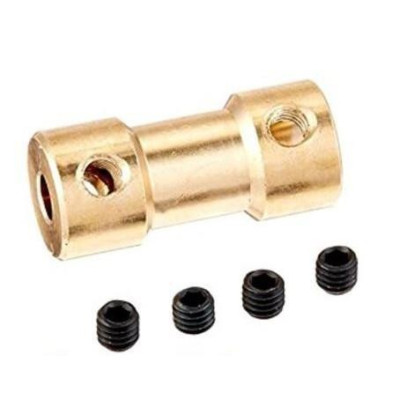
Brass Shaft Coupler, 2mm to 2mm, 20 x 9 mm, with Set Screws
Brass coupler for securely connecting a 2 mm shaft in mechanical and electronic applications, providing stable motion transmission and precise alignment. Includes set screws for quick mounting and firm grip, with outer dimensions of 20 x 9 mm, compact and wear-resistant construction, suitable for DIY projects, robots and fine mechanisms.
Buying this product earns you 0.30 RON in loyalty points.

International fast shipping within EU. Free Shipping for orders above 100 EUR in most EU countries.

We ship from our stock within 24H

You earn points with every order, worth 5%.
The rigid brass coupler connects two 2 mm shafts located on the same line and transmits the rotary motion from one to the other. It is suitable for connecting a small motor to a propeller, a gear, a pump or a rotary sensor, in robotics projects, RC models, 3D printer mechanisms and laboratory setups built in the workshop.
The part is a lathe-turned cylindrical brass sleeve, with a shaft bore at each end, both 2 mm. The middle is thinner than the ends, and the body measures 20 mm in length and 9 mm in outer diameter. Because the coupler is rigid, the two shafts turn at the same speed, with no elastic element between them.
The main features include one radial threaded hole at each end, into which a headless set screw with a hexagonal socket is screwed. The screw presses on the shaft and locks it by friction. The package includes 4 set screws. The part is purely mechanical and requires no power supply.
Specifications:
Material: Brass
Type: Rigid shaft coupler
End 1 shaft diameter: 2 mm
End 2 shaft diameter: 2 mm
Shaft fixing: Headless set screw with hexagonal socket, one threaded hole at each end
Included screws: 4 pcs
Dimensions: 20 x 9 mm
Layout:
| Element | Function |
|---|---|
| End 1 | 2 mm bore for the first shaft, usually the motor shaft. |
| End 2 | 2 mm bore for the second shaft, usually the load shaft. |
| Threaded hole of end 1 | Receives a set screw that locks the first shaft. |
| Threaded hole of end 2 | Receives a set screw that locks the second shaft. |
| Thin central section | Joins the two ends of the coupler. |
| Set screws | Tightening a screw presses on the shaft and locks it in the coupler. Loosening it allows the shaft to be removed or repositioned. |
Usage:
Disconnect the motor power supply before mounting, because an accidental start while tightening the screws can injure you or twist the shaft.
Check that both shafts have a diameter of 2 mm and are free of burrs, then clean the threaded holes of chips.
Loosen the set screws until they no longer protrude into the central bore, so that the shafts can slide freely into the coupler.
Insert the first shaft into end 1 and the second shaft into end 2, leaving a gap of about 1 mm between their tips so that they do not press against each other.
Align the two shafts on the same line, checking from two perpendicular directions.
Screw each set screw straight in by hand until it touches the shaft, then tighten it with a suitable hex key, first on the motor shaft and then on the load shaft. Do not overtighten, because brass is a soft metal and the thread can be damaged.
If the shaft has a flat surface, position the screw on it for a better grip.
Turn the shafts by hand and check that the movement is smooth, without play and without a hard spot. The mounting is correct when the shafts cannot be pulled out by hand.
Check the screws after the first few minutes of operation and then periodically, because vibrations can loosen them.
- Dimensions
- 20 x 9 mm
- Material
- Brass
- Type
- Rigid shaft coupling
Produs destinat utilizarii in proiecte electronice, automatizari, prototipare, educatie si cercetare.
Produsul trebuie utilizat numai conform specificatiilor tehnice mentionate in descriere si/sau in documentatia produsului.
Avertismente generale de siguranta:
Nu utilizati produsul la tensiuni, curenti sau temperaturi peste valorile specificate.
Montajul si conectarea trebuie realizate de persoane cu cunostinte tehnice minime in domeniul electric/electronic.
Evitati scurtcircuitele, inversarea polaritatii si conectarea gresita a alimentarii.
Nu lasati produsul alimentat nesupravegheat in timpul testelor.
Produsul nu este jucarie si nu este destinat copiilor.
Pentru modulele electronice, se recomanda utilizarea in carcase, panouri sau montaje protejate, dupa caz.
Identificare produs:
Denumirea produsului, codul/SKU-ul si caracteristicile tehnice sunt mentionate in pagina produsului si/sau pe eticheta ambalajului.
Producator / Importator / Distribuitor:
Sigmanortec S.R.L.
Calea Bucuresti nr. 9, Targu Jiu, Gorj, Romania
E-mail: [email protected]
Website: www.sigmanortec.ro
Persoana responsabila in UE:
Sigmanortec S.R.L.
Calea Bucuresti nr. 9, Targu Jiu, Gorj, Romania
E-mail: [email protected]
Documentatie si siguranta:
Pentru informatii suplimentare, fise tehnice, declaratii de conformitate sau instructiuni, ne puteti contacta la [email protected].
The 2 mm brass shaft coupler is a passive mechanical part used to join two shafts that sit on the same line, for example the shaft of a small motor and the shaft of a propeller, a gear, a pump or a rotary sensor. This tutorial explains step by step how to mount it, how to align the shafts and how to check the result, without electronic circuits and without a program.
The body measures 20 x 9 mm, has two shaft ends and comes with fixing screws. You will find it in robotics projects, RC models, 3D printer mechanisms and workshop laboratory setups.

How it works:
The coupler is a cylindrical sleeve with a 2 mm bore for each shaft. In the wall of each end there is a threaded hole into which a grub screw (headless set screw) is fitted. When the screw is tightened, its tip presses on the shaft, and the friction force between the screw, the shaft and the sleeve transmits the rotation from one shaft to the other. The middle of the coupler is thinner than the ends and only joins the two halves.
The coupler is rigid, so the two shafts rotate at the same speed: n(output) = n(input). Torque is also transmitted, and the mechanical power is P = M x ω, where ω = 2 x π x n / 60 and is expressed in rad/s. For example, a motor running at 3000 rpm has ω = 2 x 3.14 x 3000 / 60 = 314 rad/s. At a torque of 5 mN·m, the transmitted power is 0.005 x 314 = 1.57 W. These values are only an example of calculation for sizing your project.
The wall thickness around a 2 mm shaft is (9 - 2) / 2 = 3.5 mm. The thick wall makes the part resistant to the tightening of the screws, but brass is a soft metal, and overtightening will mark the shaft and can damage the thread.
Connection:
There are no electrical pins or terminals. The connection is purely mechanical, between the two shafts and the two fixing screws. The table shows what goes into each end of the coupler.
| Product pin | Connects to | Role |
|---|---|---|
| Coupler end 1 | The 2 mm shaft of the motor or of the motion source | Takes up the rotation |
| Coupler end 2 | The 2 mm shaft of the load (propeller, wheel, gear, pump, sensor) | Passes the motion on |
| Fixing screw of end 1 | Threaded hole of end 1 | Locks the shaft in end 1 |
| Fixing screw of end 2 | Threaded hole of end 2 | Locks the shaft in end 2 |
Before mounting, disconnect the power supply of the motor. A motor that starts accidentally while you are tightening the screws can injure you or twist the shaft.
Buttons, adjustments and indicators:
The part has no buttons, potentiometers, LEDs or display. The only elements you operate are the fixing screws, one for each end.
| Element | What it does | How to use it |
|---|---|---|
| Fixing screw of end 1 | Fixes the first shaft in the coupler | Tightened with a suitable hex key, after the shaft has been inserted to the desired depth. Loosened to remove the shaft or to reposition it. |
| Fixing screw of end 2 | Fixes the second shaft in the coupler | Tightened the same way as the first, after the two shafts have been aligned. |
| Threaded holes | Receive the fixing screws | Cleaned of swarf before mounting. The screw is driven in straight, without forcing it. |
To fix a shaft, insert it into the end of the coupler until it reaches the desired depth. Screw the fixing screw in by hand until it touches the shaft, then tighten it with the hex key. A light pull on the shaft shows whether it has gripped. If the shaft has a flat surface, seat the screw on it, because the grip is better than on a round shaft.
The starting position is with both screws loosened, so that the two shafts can enter the coupler freely. The screws are tightened only after the shafts have been aligned. The mounting is successful when the shafts cannot be pulled out by hand and, when rotated slowly, no play appears.
Setup:
First check that the shafts have a diameter of 2 mm and that they have no burrs. A burr prevents the shaft from entering fully and spoils the centring. Loosen the fixing screws until they no longer protrude into the central bore.
Insert the first shaft into end 1, then the second shaft into end 2. Leave a gap of about 1 mm between the ends of the shafts, so that they do not press against each other. If the shafts touch, the coupler transmits axial forces as well, and the motor bearings wear out.
Align the two shafts on the same line, looking from two perpendicular directions. Tighten first the screw on the motor shaft, then the one on the load shaft. Turn by hand several times and check that the movement is smooth, without a hard spot or visible wobble.
The setting is maintained simply by the mechanical tightness. During operation, vibrations can loosen the screws, so check them after the first few minutes of work and then periodically.
Usage example:
The example connects a small DC motor with a 2 mm shaft to a 2 mm shaft that drives a propeller or a small pump. The motor is fixed on one support, and the load on a second support, with the shafts on the same line.
Disconnect the power supply of the motor. Loosen both fixing screws, then insert the motor shaft into end 1 and the load shaft into end 2, with a gap of about 1 mm between them. Check the alignment, tighten the screw of end 1, then the one of end 2.
Turn the load shaft by hand. If the motor shaft turns along with it, without play, the mounting is correct. Power the motor at a low speed. The shafts must rotate together, without vibration and without metallic noise. Stop the motor, tighten the screws again after the first few minutes of work, then use the mounting normally.
Common problems:
The shaft slips in the coupler. The cause is usually a screw that is too loose or seated on a polished shaft. Tighten the screw more firmly. If that is not enough, make a flat surface on the shaft and seat the screw on it.
The mounting vibrates or a noise is heard at high speed. The cause is usually imperfect alignment of the shafts or a slightly bent shaft. Loosen the screws, realign the shafts on the same line and tighten again.
The shaft does not enter the coupler fully. The cause is a burr on the shaft or swarf in the bore. Remove the burr with a fine file and clean the bore.
The screws loosen after a while. The cause is vibration. Check them periodically and tighten them again, without excessive force.
The motor heats up or the bearings wear out quickly. The cause may be the lack of space between the shafts, which press axially against each other. Leave a gap of about 1 mm between the ends of the shafts.
Limitations and tips:
The coupler is rigid and does not compensate for misalignment. The two shafts must be well aligned, otherwise vibrations and wear will appear. It is suitable for 2 mm shafts at both ends and for small loads, where the transmission is made by friction, not by a key or keyway.
Friction-based fixing has torque limits. For loads that require a higher torque, a flat surface on the shaft increases the safety of the transmission. The coupler can be used further in RC models, small transmission mechanisms, pumps and laboratory rotary mechanisms.