

Product images are for informational purposes only and may vary slightly depending on the batch and supplier. Product specifications and prices may be subject to change without notice. We do our best to provide accurate and complete product specifications, but they may not be completely accurate. If you encounter any such situation, please let us know.
The product is intended for specialists and requires qualified and authorized personnel. The product does not include assembly/use instructions . Putting the product into operation by unqualified persons leads to the loss of the warranty according to the Terms and Conditions on the site.
The specified technical parameters (current, power, etc.) represent maximum allowable values under ideal operating conditions. For safe use and optimal lifespan, it is recommended to operate the product continuously at no more than 50% of the specified maximum values.
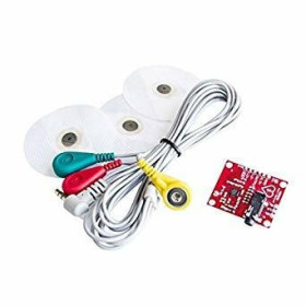
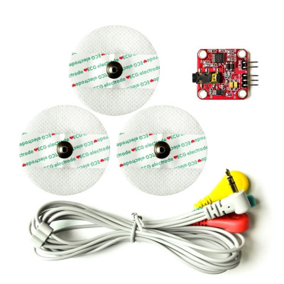
Electromyogram Sensor Module, EMG, electrodes H124SG
Kit for measuring electrical muscle activity, useful in biofeedback projects and EMG analysis with Arduino or other development boards. Includes the module and 3 self-adhesive gel pads and wires, offers 0V to Vs analog output for easy reading, mounts quickly on the breadboard, works with dual power supply between plus minus 3.5 and plus minus 9VDC.
Buying this product earns you Ft318.08 in loyalty points.

International fast shipping within EU. Free Shipping for orders above 100 EUR in most EU countries.

We ship from our stock within 24H

You earn points with every order, worth 5%.
The EMG sensor module is a product designed to measure the electrical activity of muscles through surface electromyography (sEMG).
Based on the TL084 quad operational amplifier with JFET input, the module offers a very high input impedance, low noise, and a slew rate of 16 V/µs, ensuring faithful acquisition of the muscle signal.
The module is compatible with Arduino, STM32, ESP32 platforms, and any other platform that has an analog-to-digital converter (ADC).
The raw EMG signal is bipolar, oscillating between positive and negative values relative to ground. The module internally processes this signal in three stages: differential amplification with adjustable gain, full-wave rectification, and integration (smoothing), providing at the SIG output a unipolar analog signal ranging from 0 V to +Vs, ready to be read by an ADC. The gain is determined by the formula Gain = 207 x (Rgain / 1 kΩ), with a default Rgain resistor of 43 kΩ mounted on the PCB, resulting in a gain of approximately 8900x, ideal for typical muscle signals of 2-5 mV.
Electrode connection is made through a standard 3.5 mm jack connector, compatible with H124SG adhesive electrodes.
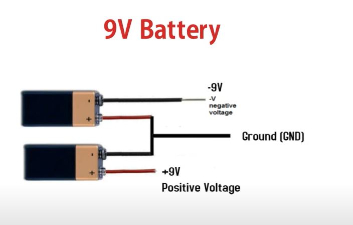
The module requires a bipolar power supply (+Vs, GND, -Vs), preferably two 9 V batteries connected in series.
The current consumption is approximately 1 mA, making it suitable for portable battery-powered applications. The small size of 25.4 x 25.4 mm and the pins compatible with standard breadboards facilitate quick integration into any prototype.
The module is recommended for applications in robotics, prosthetics, muscle-controlled video games, medical devices, wearable equipment, and human-machine interaction systems.
The module outputs an analog signal between 0V and VS (Voltage Supply). This module requires both positive and negative power supplies simultaneously. For this reason, you will need two power sources or an H-Bridge to generate +5VDC and -5VDC.
Specifications:
Amplifier: TL084 (quad JFET op-amp)
Power supply: +/-3 V to +/-30 V (bipolar)
Recommended voltage: +/-9 V (2 x 9 V batteries in series)
Operating current: ~1 mA
SIG output voltage: 0 V ... +Vs (unipolar)
Gain formula: Gain = 207 x (Rgain / 1 kΩ)
Default Rgain: 43 kΩ (gain ~8900x)
Typical differential input voltage: 2-5 mV
Electrode connector: 3.5 mm jack
Compatible electrodes: H124SG (adhesive)
PCB dimensions: 25.4 x 25.4 mm (1.0 x 1.0 in)
Pin spacing: 2.54 mm (0.1 in)
Operating temperature: -40°C ... +85°C
Module dimensions mm: 20.6 x 20.6mm
Pinout:
| Pin | Signal | Description |
|---|---|---|
| +Vs | PWR | Positive power supply (+9 V) |
| GND | PWR | Common ground (between the 2 batteries) |
| -Vs | PWR | Negative power supply (-9 V) |
| SIG | OUT | Analog signal output (0...+Vs) |
| GND | GND | Output ground (connected to MCU GND) |
Usage:
Connect the first 9 V battery with the positive pole to the +Vs pin of the module.
Connect the junction point between the two batteries (negative pole of the first battery and positive pole of the second) to the GND pin of the module.
Connect the negative pole of the second battery to the -Vs pin of the module.
Clean the skin area above the target muscle (biceps, forearm, calf, etc.) and let it dry.
Apply the three H124SG adhesive electrodes: two electrodes on the muscle belly, 1-3 cm apart, and a reference electrode in an electrically neutral adjacent area.
Connect the 3.5 mm jack cable of the electrodes to the module connector.
Connect the SIG pin to the analog input of the microcontroller (e.g., A1 on Arduino). Attention: if you use a +/-9 V power supply, the voltage on SIG can reach 9 V, exceeding the Arduino ADC limit of 5 V. In this case, use a voltage divider (e.g., 10 kΩ and 12 kΩ) to reduce the signal to a maximum of 5 V, or lower Vs to +/-5 V.
Connect the module's GND pin to the microcontroller's GND.
Upload the test code to the microcontroller and open the Serial Monitor to view the ADC values in real time.
The raw muscle electrical signal is bipolar, oscillating both in the positive and negative regions relative to ground. The TL084 amplifier on the module requires the -Vs voltage to properly process both polarities. Without it, anything below 0 V would be clipped, distorting the signal and losing useful information. The negative power supply is only necessary internally for the amplification stage. At the SIG output, the signal is always positive (0 V ... +Vs), directly compatible with the ADC of any microcontroller.
Microcontroller Connection:
| Module Pin | Signal | Arduino UNO | ESP32 | Description |
|---|---|---|---|---|
| +Vs | PWR | External power supply | External power supply | Positive power supply (+9 V) |
| GND | PWR | Power ground | Power ground | Common power ground |
| -Vs | PWR | External power supply | External power supply | Negative power supply (-9 V) |
| SIG | OUT | A0 | GPIO34 / GPIO35 / GPIO36 / GPIO39 | Analog signal output |
| GND | GND | GND | GND | Common signal ground |
Produs destinat utilizarii in proiecte electronice, automatizari, prototipare, educatie si cercetare.
Produsul trebuie utilizat numai conform specificatiilor tehnice mentionate in descriere si/sau in documentatia produsului.
Avertismente generale de siguranta:
Nu utilizati produsul la tensiuni, curenti sau temperaturi peste valorile specificate.
Montajul si conectarea trebuie realizate de persoane cu cunostinte tehnice minime in domeniul electric/electronic.
Evitati scurtcircuitele, inversarea polaritatii si conectarea gresita a alimentarii.
Nu lasati produsul alimentat nesupravegheat in timpul testelor.
Produsul nu este jucarie si nu este destinat copiilor.
Pentru modulele electronice, se recomanda utilizarea in carcase, panouri sau montaje protejate, dupa caz.
Identificare produs:
Denumirea produsului, codul/SKU-ul si caracteristicile tehnice sunt mentionate in pagina produsului si/sau pe eticheta ambalajului.
Producator / Importator / Distribuitor:
Sigmanortec S.R.L.
Calea Bucuresti nr. 9, Targu Jiu, Gorj, Romania
E-mail: [email protected]
Website: www.sigmanortec.ro
Persoana responsabila in UE:
Sigmanortec S.R.L.
Calea Bucuresti nr. 9, Targu Jiu, Gorj, Romania
E-mail: [email protected]
Documentatie si siguranta:
Pentru informatii suplimentare, fise tehnice, declaratii de conformitate sau instructiuni, ne puteti contacta la [email protected].
// EMG Sensor Module - Basic ADC Read
// Compatible with Arduino Uno, Nano, Mega
// Connect SIG to A1, GND to GND
// Use voltage divider if supply is +/-9V
const int emgPin = A1;
void setup() {
Serial.begin(9600);
}
void loop() {
int rawValue = analogRead(emgPin);
float voltage = rawValue * (5.0 / 1023.0);
Serial.print("ADC: ");
Serial.print(rawValue);
Serial.print(" Voltage: ");
Serial.print(voltage, 2);
Serial.println(" V");
delay(10);
}