
Product images are for informational purposes only and may vary slightly depending on the batch and supplier. Product specifications and prices may be subject to change without notice. We do our best to provide accurate and complete product specifications, but they may not be completely accurate. If you encounter any such situation, please let us know.
The product is intended for specialists and requires qualified and authorized personnel. The product does not include assembly/use instructions . Putting the product into operation by unqualified persons leads to the loss of the warranty according to the Terms and Conditions on the site.
The specified technical parameters (current, power, etc.) represent maximum allowable values under ideal operating conditions. For safe use and optimal lifespan, it is recommended to operate the product continuously at no more than 50% of the specified maximum values.
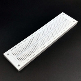
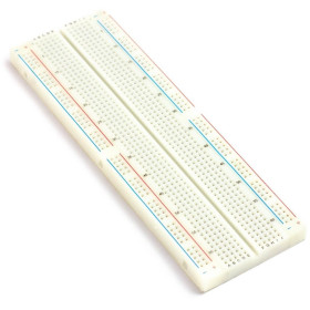
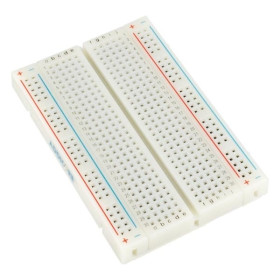
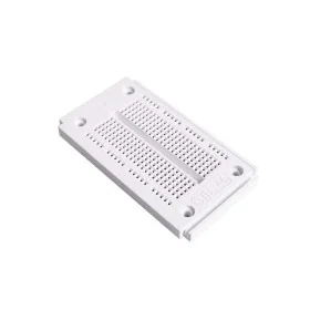
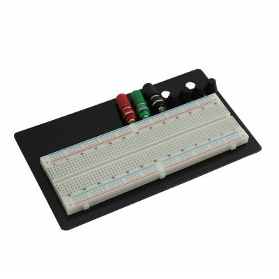
Breadboard MB-102, 830 Points, with Metal Plate, 3 Power Jacks, 4 Rubber Feet
Prototyping board for quick solderless circuit testing, with 830 points and MB-102 breadboard mounted on a metal plate for stability, includes 3 jacks for power and quick connections, sits firmly on the table with 4 rubber feet, ideal for development, debugging and electronics demonstrations.
Buying this product earns you 2.27 RON in loyalty points.

International fast shipping within EU. Free Shipping for orders above 100 EUR in most EU countries.

We ship from our stock within 24H

You earn points with every order, worth 5%.
The MB-102 prototyping breadboard with 830 contact points is mounted on a metal plate and is equipped with 3 power jacks and 4 rubber feet. It allows electronic circuits to be assembled and tested without soldering, being suitable for prototypes, experiments, school laboratories and quick verification of schematics before making the printed circuit board.
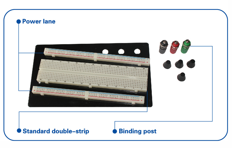
The central area has 63 columns with 10 rows each, marked a - e and f - j, i.e. 630 points. In each column the holes a - e are connected to each other, and the holes f - j are connected to each other, the two halves being separated by the centre channel, over which DIP integrated circuits are mounted. The 4 power rails have 50 points each, 200 points in total, and the distance between holes is 2.54 mm.
The main features include the metal plate on which the breadboard is fixed, the 3 power jacks (red, green and black) for connecting wires or banana connectors, and the 4 rubber feet that keep the board stable on the table. The jacks are not internally connected to the breadboard, and power is supplied at low voltages, from a power supply or a battery, through wires connected between the jacks and the power rails.
Specifications:
Breadboard model: MB-102
Contact points: 830
Central area: 63 columns x 10 rows (a - e and f - j), 630 points
Power rails: 4 x 50 points, 200 points
Hole spacing: 2.54 mm
Accepted wires: 21 - 26 AWG
Contacts: Nickel-plated spring strips
Power jacks: 3 (red, green, black)
Support: Metal plate
Feet: 4 rubber
Dimensions: 183 x 96.5 mm
Layout:
| Element | Function |
|---|---|
| Red jack | Connection point for the positive supply. It is not internally connected to the breadboard, it is connected with a wire from its base to the desired + rail. |
| Black jack | Connection point for ground. It is connected with a wire from its base to the desired - rail. |
| Green jack | Free jack, usable for a second voltage or as a measurement point for a multimeter probe. It is not internally connected to the breadboard. |
| Power rails (4) | Distribute the positive (red line) and ground (blue line) along the entire length of the board. The top and bottom rails are separate and are connected to each other with wires. The holes are grouped in 5. |
| Columns a - e and f - j | The holes in the same half of a column are electrically connected to each other. |
| Centre channel | Separates the two halves of each column. DIP integrated circuits are mounted over it, so that each pin has its own column. |
| Metal plate | Rigid support on which the breadboard is fixed. |
| Rubber feet (4) | Keep the board stable on the table and prevent it from sliding. |
Usage:
Place the board on a flat surface and check that all 4 rubber feet rest on the table.
Power the breadboard only at low voltages and never connect mains voltage of 220 VAC.
Connect the power supply or battery to the red (positive) and black (ground) jacks, then connect the base of each jack to the corresponding power rail, the positive to the rail marked with + and the ground to the rail marked with -.
To attach a wire to a jack, unscrew the cap a few turns, insert the stripped wire through the hole under the cap and tighten the cap until the wire no longer moves, then gently pull the wire to check that it holds. 4 mm banana connectors can be used in the head of the jack, but check that they fit well.
If you need power on both edges, connect the top + rail to the bottom + rail and the top - rail to the bottom - rail with wires, because the top and bottom rails are not connected to each other.
Check the continuity of each power rail with a multimeter before use, because on some boards of this type the rails may be interrupted in the middle. If the multimeter does not indicate continuity, connect the two halves with a short wire.
Mount DIP integrated circuits over the centre channel and insert components into the columns, so that the legs that must be connected to each other are in the same half of the column.
Use solid core wire or Dupont wires with a diameter of approximately 0.4 - 0.8 mm. Wires that are too thick deform the spring strips and damage the contact, and those that are too thin do not grip well.
When connecting a battery, connect the black wire first and then the red wire, and when disconnecting, remove the red wire first. For stable results use short wires and do not force components into the holes.
Produs destinat utilizarii in proiecte electronice, automatizari, prototipare, educatie si cercetare.
Produsul trebuie utilizat numai conform specificatiilor tehnice mentionate in descriere si/sau in documentatia produsului.
Avertismente generale de siguranta:
Nu utilizati produsul la tensiuni, curenti sau temperaturi peste valorile specificate.
Montajul si conectarea trebuie realizate de persoane cu cunostinte tehnice minime in domeniul electric/electronic.
Evitati scurtcircuitele, inversarea polaritatii si conectarea gresita a alimentarii.
Nu lasati produsul alimentat nesupravegheat in timpul testelor.
Produsul nu este jucarie si nu este destinat copiilor.
Pentru modulele electronice, se recomanda utilizarea in carcase, panouri sau montaje protejate, dupa caz.
Identificare produs:
Denumirea produsului, codul/SKU-ul si caracteristicile tehnice sunt mentionate in pagina produsului si/sau pe eticheta ambalajului.
Producator / Importator / Distribuitor:
Sigmanortec S.R.L.
Calea Bucuresti nr. 9, Targu Jiu, Gorj, Romania
E-mail: [email protected]
Website: www.sigmanortec.ro
Persoana responsabila in UE:
Sigmanortec S.R.L.
Calea Bucuresti nr. 9, Targu Jiu, Gorj, Romania
E-mail: [email protected]
Documentatie si siguranta:
Pentru informatii suplimentare, fise tehnice, declaratii de conformitate sau instructiuni, ne puteti contacta la [email protected].
This tutorial does not use any development board or any program. The MB-102 breadboard with 830 points and metal plate is a prototyping tool, on which you mount circuits without soldering. The metal plate and the 4 rubber feet keep it stable on the table, and the 3 power terminals (red, green and black) let you bring voltage from a power supply or a battery without holding wires in the air.
The tutorial shows step by step how to put it into operation, powered from a 9 V 6LR61 battery with snap connector, and how to mount a first circuit on it.
How it works:
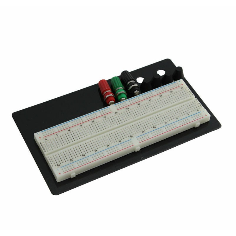
Under the plastic holes are metal contact strips that grip the component leg. The central area has 63 columns, each with 10 rows, marked a - e and f - j. In each column the holes a - e are connected to each other, and the holes f - j are connected to each other. The two halves do not communicate, because they are separated by the centre channel. For this reason DIP integrated circuits are mounted across the channel, so that each pin has its own column.
The central area has 63 x 10 = 630 points. The 4 power rails have 50 points each, that is 200 points in total. Together this gives 630 + 200 = 830 points. The distance between holes is 2.54 mm, the same as for most DIP integrated circuits and modules with pins in a row.
On the top edge, the outer row is - (blue line) and the inner row is + (red line). On the bottom edge, the inner row is - and the outer row is +. The holes in a rail are grouped in 5. Each rail runs along its entire length, but the top and bottom ones are separated and are connected to each other with wires.
The three terminals are not internally connected to the breadboard. Each terminal needs a wire from its base to a power rail. The terminal is only a convenient point for connecting the source or a measuring point.
Connection:
Power the breadboard only with low voltages. In the assembly, the 9 V 6LR61 battery with snap connector is connected to the red and black terminals, and from there the voltage reaches the power rails through short wires. Never connect 220 VAC mains voltage to this breadboard. If you use a 5 V or 3.3 V source, the connection is the same. Choose the voltage according to the components mounted, because the logic levels and the limits of each circuit remain your responsibility.
| Product pin | Connects to | Role |
|---|---|---|
| Red terminal | + terminal of the 9 V battery (red wire of the snap connector) | Positive power input |
| Black terminal | - terminal of the 9 V battery (black wire of the snap connector) | Ground input |
| Red terminal, via a wire from its base | Top + rail (red line) | Distributes the positive on the top rail |
| Black terminal, via a wire from its base | Top - rail (blue line) | Distributes the ground on the top rail |
| Top - rail | Bottom - rail, via a wire between the two rails | Brings the ground to the bottom rail as well |
| Top + rail | Bottom + rail, via a wire between the two rails | Brings the positive to the bottom rail as well |
| Green terminal | Not connected to anything in this assembly | Free, for a second voltage or a measuring point |
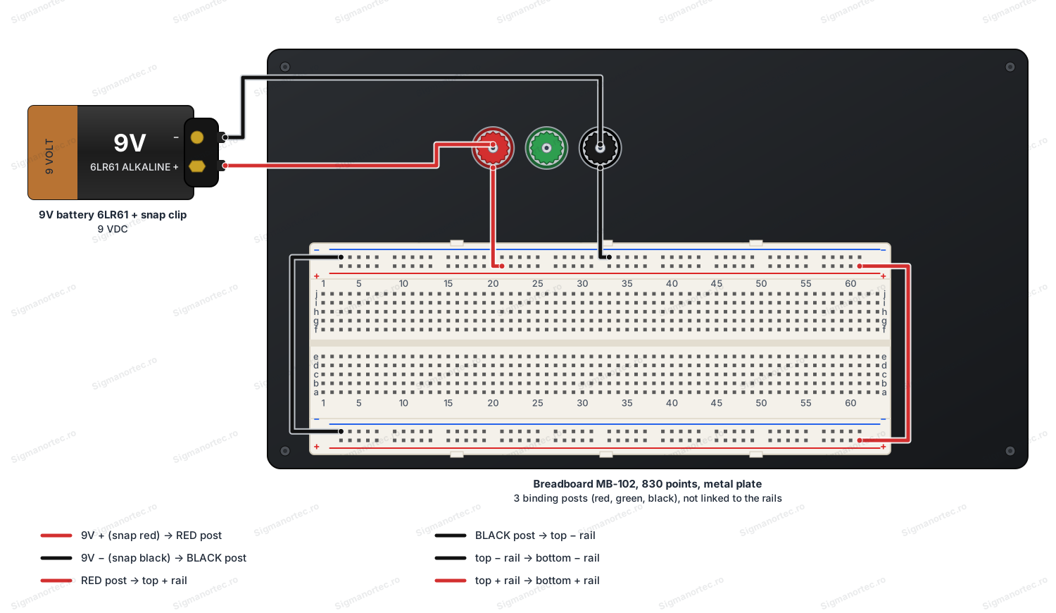
Use solid wire of about 0.4 - 0.8 mm or Dupont wires. Wires that are too thick deform the contact strips and spoil the contact, while those that are too thin do not grip well. Always connect the black wire to the rail marked - and the red wire to the rail marked +, to avoid reversing the polarity.
Buttons, adjustments and indicators:
The breadboard has no buttons, potentiometers, jumpers, switches, LEDs or display. The only elements you work with are the terminals, the power rails and the central channel.
| Element | What it does | How to use it |
|---|---|---|
| Red terminal | Input for the positive supply | Loosen the cap, insert a stripped wire or a 4 mm banana connector through the hole under it, then tighten the cap. Connect the base of the terminal to the + rail with a wire. |
| Black terminal | Input for ground | The same as the red terminal, but it is connected to the - rail, which you use as ground. |
| Green terminal | Free terminal | Use it for a second voltage or as a measuring point for the probe of a multimeter. It is not connected to anything without a wire. |
| Power rails (4) | Distribute the positive and ground along the whole length of the board | Connected from the terminals with wires. The top and bottom ones are joined with wires from + to + and from - to -. |
| Columns a - e and f - j | Connect the holes in the same half of the column to each other | Insert the component leg and the wire that continues it into the same half of the column. |
| Central channel | Separates the two halves of each column | Mount DIP integrated circuits across it. |
| The 4 rubber feet | Keep the metal plate stable on the table | No action required. |
To connect a terminal, unscrew the cap a few turns, insert the stripped wire through the hole under it and tighten the cap until the wire no longer moves. Then pull the wire gently to check that it holds. If you prefer banana connectors, they usually fit into the head of the terminal, but check that they fit well before relying on them.
Check each rail before use. On some MB-102 boards the power rails are interrupted in the middle. Set the multimeter to continuity, place one probe at one end of the rail and the other probe at the opposite end. If the multimeter does not beep, connect the two halves with a short wire.
Setup:
The breadboard has no settings that are saved, so the preparation is reduced to a few steps. Place the board on a flat surface and check that all 4 rubber feet are on the table. Connect the terminals to the rails with short wires, then connect the top and bottom rails to each other, as in the diagram. Only then connect the battery to the terminals.
Connect the black wire first and then the red wire. When you remove the power, remove the red wire first.
Measure the voltage with the multimeter between the + rail and the - rail. For the 9 V battery the value should be close to 9 V. If the reading is close to 0 V, check the terminal connections, the continuity of the rail and the polarity.
Usage example:
We will light a red LED, powered from the 9 V battery, with a 470 ohm current-limiting resistor. With a voltage drop across the LED of about 2 V, the current is (9 - 2) / 470, that is about 15 mA, a safe value for a standard 5 mm LED.
Prepare the power supply as described in the Setup section, with the top + rail connected to the red terminal and the top - rail connected to the black terminal.
Insert one end of the 470 ohm resistor into the top + rail and the other end into column 20, in hole a.
Insert the long leg of the LED (the anode) into column 20, in hole b, and the short leg (the cathode) into column 21, in hole b. The two legs are in different columns, so the LED is not short-circuited.
Connect hole c in column 21 to the top - rail with a wire. When you connect the battery, the LED should light up. If it does not light, turn the LED 180 degrees, because it is mounted the wrong way round.
Common problems:
The circuit does not receive any voltage. The usual cause is that the terminals are not connected to the rails, since they have no internal connection to the breadboard. Connect the base of each terminal to the corresponding rail with a wire.
The bottom rail has no voltage. The top and bottom rails are not connected to each other. Add one wire between the + rails and one wire between the - rails.
Part of the rail is not powered. On some MB-102 boards the rail is interrupted in the middle. Check the continuity with the multimeter and connect the two halves with a short wire.
A DIP integrated circuit does not work and has its pins short-circuited. It was probably mounted on only one half of the board. Mount it across the central channel, so that the pins on the two sides are in different halves of the columns.
The contacts are unreliable. Wires that are too thick deform the contact strips, and those that are too thin do not grip well. Use solid wire of about 0.4 - 0.8 mm or Dupont wires.
The wire clamped in the terminal moves. The cap is not tightened enough. Tighten the cap until the wire no longer moves and check by pulling the wire gently.
Limitations and tips:
The breadboard is intended for low voltages and small currents. Do not connect 220 VAC mains voltage and do not pass high currents through the contact strips, because they heat up and lose their elasticity. For high frequencies or sensitive signals, long wires and the capacitances between columns can affect the circuit, so use wires that are as short as possible.
The green terminal remains free and can serve for a second voltage or as a measuring point for the multimeter. Once a circuit works on the breadboard, you can move it to a printed circuit board or to a soldered prototyping board.