

Product images are for informational purposes only and may vary slightly depending on the batch and supplier. Product specifications and prices may be subject to change without notice. We do our best to provide accurate and complete product specifications, but they may not be completely accurate. If you encounter any such situation, please let us know.
The product is intended for specialists and requires qualified and authorized personnel. The product does not include assembly/use instructions . Putting the product into operation by unqualified persons leads to the loss of the warranty according to the Terms and Conditions on the site.
The specified technical parameters (current, power, etc.) represent maximum allowable values under ideal operating conditions. For safe use and optimal lifespan, it is recommended to operate the product continuously at no more than 50% of the specified maximum values.
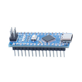
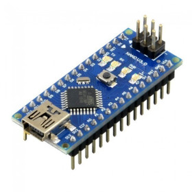
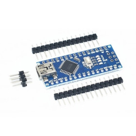
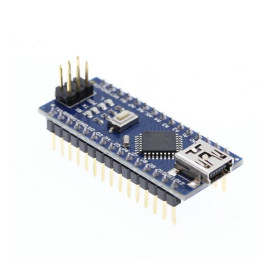
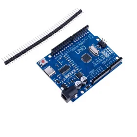
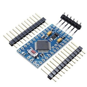
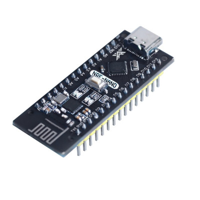
NRF-Nano V3.0 development board, CH340, ATMega328p with NRF24L01, Type C
Compact Arduino Nano compatible development board, ideal for IoT projects and wireless communication, integrates NRF24L01 transceiver for fast and stable radio links, uses ATMega328P at 16MHz with 5V logic, keeps pinout identical to Nano V3 for easy integration, programming and power supply via USB Type C with CH340G.
Shipping by Wednesday 4 November
Buying this product earns you 3.48 RON in loyalty points.

International fast shipping within EU. Free Shipping for orders above 100 EUR in most EU countries.

We ship from our stock within 24H

You earn points with every order, worth 5%.
The NRF-Nano V3.0 development board combines on the same printed circuit board an ATmega328P microcontroller compatible with the Arduino Nano V3 and a 2.4 GHz nRF24L01+ radio transceiver, with a printed antenna. It is suitable for wireless sensor networks, remote controls, home automation, data transmission modules between two or more boards, and any project where you need a microcontroller and a radio link in a Nano format.
The ATmega328P microcontroller runs at 16 MHz, with 32 KB of Flash memory (of which 2 KB are occupied by the bootloader), 2 KB of SRAM and 1 KB of EEPROM, and the logic level is 5 V. Communication with the computer is done through the CH340G USB-to-serial converter, and the USB Type-C connector serves both for programming and power supply. The nRF24L01+ radio is connected to the microcontroller via SPI, with CE on D7 and CSN on D8, and pins D7, D8, D11, D12 and D13 can no longer be used for other functions.
Among the main features are the USB Type-C connector, the CH340G USB-to-serial converter, the radio’s printed antenna, the RESET button, the 3.3 V regulator that powers the radio, the test LED connected to D13, and two rows of 15 pins each with the same layout as the standard Nano V3. Power is supplied at 5 VDC via USB Type-C or at 7 - 12 VDC (recommended 9 VDC) on the VIN pin.
The board is programmed from the Arduino IDE as an Arduino Nano and is compatible with Arduino Nano V3 libraries and sketches. Through radio it communicates with other NRF-Nano boards or with any nRF24L01+ module connected to Arduino, ESP32, STM32 or Raspberry Pi, and through USB it can be connected to a computer.
Specifications:
Supply voltage: 7 - 12 VDC (recommended 9 VDC) on the VIN pin or 5 VDC via USB Type-C
Current per IO pin: 40 mA
Logic voltage: 5 V
Processor: ATmega328P
Additional integrated component: nRF24L01+ transceiver (2.4 GHz)
USB to Serial driver: CH340G
USB connector: Type-C
Digital I/O pins: 14, of which 6 PWM
Analog input pins: 6
Flash memory: 32 KB, of which 2 KB used for bootloader
SRAM: 2 KB
EEPROM: 1 KB
Frequency: 16 MHz
Radio pins: CE = D7, CSN = D8, MOSI = D11, MISO = D12, SCK = D13
Dimensions: 48 x 19 mm
Layout:
| Element | Function |
|---|---|
| USB Type-C connector | Powers the board at 5 V and connects it to the computer for programming and serial communication via CH340G. |
| ATmega328P microcontroller | Runs the user program and controls the radio via SPI. |
| Printed antenna | The nRF24L01+ radio antenna for the 2.4 GHz band, made directly on the board’s PCB. |
| nRF24L01+ radio | Integrated transceiver, connected to the microcontroller via CE = D7, CSN = D8 and SPI on D11, D12, D13. |
| RESET button | A short press resets the microcontroller and restarts the program. After reset, the bootloader starts and then the uploaded program. |
| D13 test LED | Lights up when pin D13 is HIGH and turns off when it is LOW. Because D13 is also the radio SCK line, the LED may blink during radio activity. |
| CH340G converter (on the back of the board) | USB-to-serial converter used for programming and the serial monitor. |
| AMS1117-3.3 regulator (on the back of the board) | Provides the 3.3 V needed by the nRF24L01+ radio. |
| Pin headers | Two rows of 15 pins, with the same layout as on the Nano V3. |
Pinout:
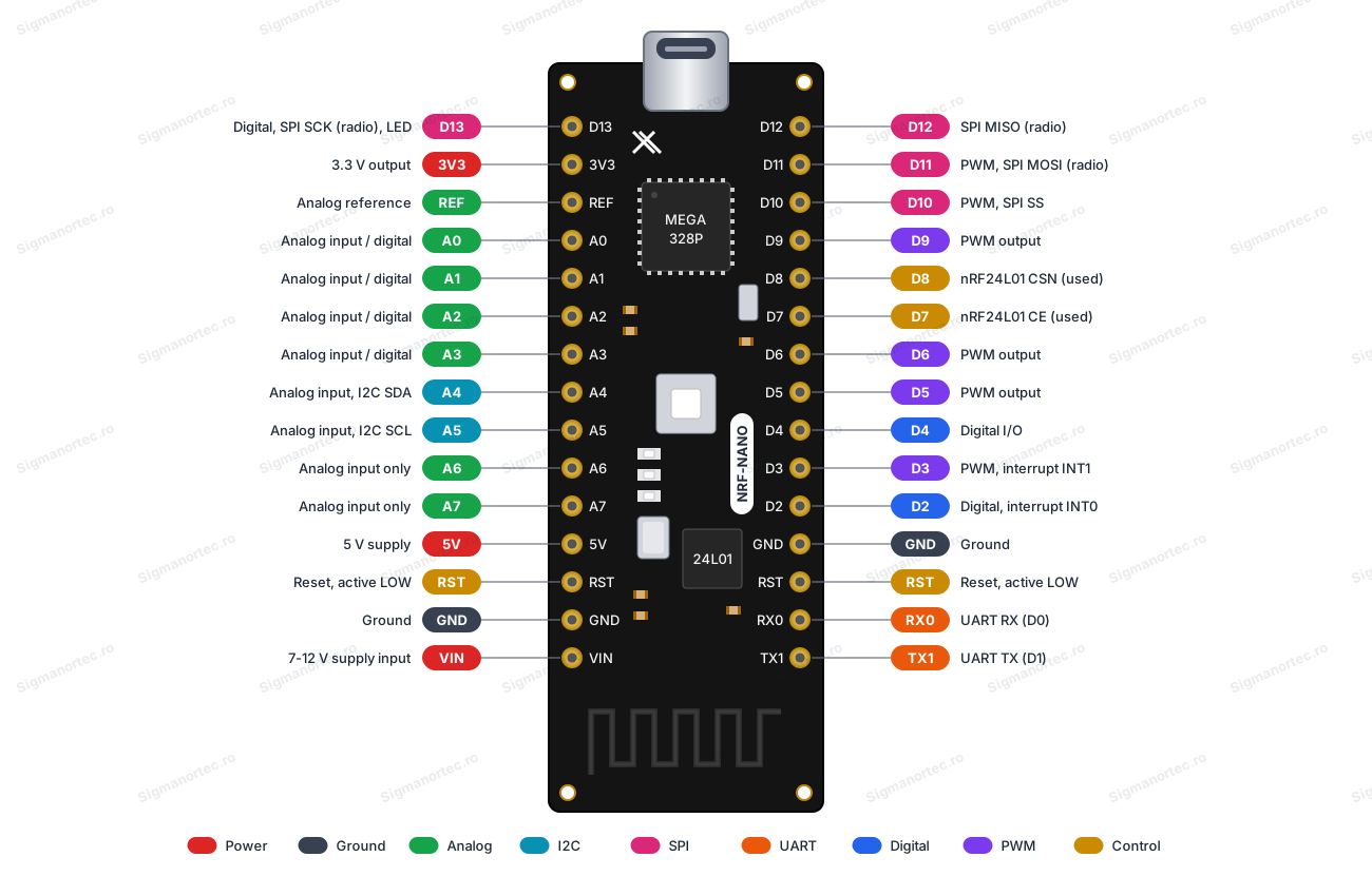
| Conector | Pin | Funcție |
|---|---|---|
| VIN / D13 row | VIN | 7 - 12 VDC power input (recommended 9 VDC) |
| VIN / D13 row | GND | Ground |
| VIN / D13 row | RST | Reset (at LOW level resets the microcontroller) |
| VIN / D13 row | 5V | 5 V supply |
| VIN / D13 row | A7, A6 | Analog inputs (analog input only) |
| VIN / D13 row | A5 - A0 | Analog inputs, also usable as digital pins (A4 = SDA, A5 = SCL for I2C) |
| VIN / D13 row | REF | External analog reference |
| VIN / D13 row | 3V3 | 3.3 V supply |
| VIN / D13 row | D13 | Digital pin, SPI SCK (used by radio), test LED |
| TX1 / D12 row | TX1 | Serial transmission (D1) |
| TX1 / D12 row | RX0 | Serial reception (D0) |
| TX1 / D12 row | RST | Reset |
| TX1 / D12 row | GND | Ground |
| TX1 / D12 row | D2 | Digital pin, external interrupt INT0 |
| TX1 / D12 row | D3 | Digital pin with PWM, external interrupt INT1 |
| TX1 / D12 row | D4 | Digital pin |
| TX1 / D12 row | D5 | Digital pin with PWM |
| TX1 / D12 row | D6 | Digital pin with PWM |
| TX1 / D12 row | D7 | CE of the nRF24L01+ radio (occupied) |
| TX1 / D12 row | D8 | CSN of the nRF24L01+ radio (occupied) |
| TX1 / D12 row | D9 | Digital pin with PWM |
| TX1 / D12 row | D10 | Digital pin with PWM, SPI SS |
| TX1 / D12 row | D11 | Digital pin with PWM, SPI MOSI (used by radio) |
| TX1 / D12 row | D12 | SPI MISO (used by radio) |
| Pin ATmega328P | Pin nRF24L01+ | Function |
|---|---|---|
| D7 | CE | Radio enable (receive or transmit mode) |
| D8 | CSN | SPI chip select |
| D11 | MOSI | Data from microcontroller to radio |
| D12 | MISO | Data from radio to microcontroller |
| D13 | SCK | SPI clock |
Use:
Connect the board to the computer using a USB-A to USB Type-C cable that supports data transfer.
If the board is not recognized with the latest CH340 driver version (2023), install the driver from the Download section.
In Arduino IDE select the Arduino Nano board and the ATmega328P processor, and if uploading the program fails, choose the ATmega328P (Old Bootloader) processor.
Power the board either through USB Type-C at 5 VDC, or on the VIN pin at 7 - 12 VDC (recommended 9 VDC), respecting polarity.
Do not apply voltages above 5 V to the I/O pins and do not exceed 40 mA on a pin.
For radio communication, install the RF24 library and create the radio object with CE = 7 and CSN = 8, that is RF24 radio(7, 8).
Do not use pins D7, D8, D11, D12 and D13 for other functions, because they are occupied by the radio.
Briefly press the RESET button to restart the program, and after uploading a new program the board starts automatically.
To test the radio link, use two NRF-Nano boards with the same radio channel and with reversed addresses between them, then follow the result on the serial monitor.
For stable results, power the board from a good power supply, keep the printed antenna away from metal parts, and avoid covering the antenna area with metal cases or wires.
Produs destinat utilizarii in proiecte electronice, automatizari, prototipare, educatie si cercetare.
Produsul trebuie utilizat numai conform specificatiilor tehnice mentionate in descriere si/sau in documentatia produsului.
Avertismente generale de siguranta:
Nu utilizati produsul la tensiuni, curenti sau temperaturi peste valorile specificate.
Montajul si conectarea trebuie realizate de persoane cu cunostinte tehnice minime in domeniul electric/electronic.
Evitati scurtcircuitele, inversarea polaritatii si conectarea gresita a alimentarii.
Nu lasati produsul alimentat nesupravegheat in timpul testelor.
Produsul nu este jucarie si nu este destinat copiilor.
Pentru modulele electronice, se recomanda utilizarea in carcase, panouri sau montaje protejate, dupa caz.
Identificare produs:
Denumirea produsului, codul/SKU-ul si caracteristicile tehnice sunt mentionate in pagina produsului si/sau pe eticheta ambalajului.
Producator / Importator / Distribuitor:
Sigmanortec S.R.L.
Calea Bucuresti nr. 9, Targu Jiu, Gorj, Romania
E-mail: [email protected]
Website: www.sigmanortec.ro
Persoana responsabila in UE:
Sigmanortec S.R.L.
Calea Bucuresti nr. 9, Targu Jiu, Gorj, Romania
E-mail: [email protected]
Documentatie si siguranta:
Pentru informatii suplimentare, fise tehnice, declaratii de conformitate sau instructiuni, ne puteti contacta la [email protected].
Reviews (1) - Review moderation

Se pare ca este o combinatie nereusita intre un Nano si nRF24l01+ Foarte pretentios cu alimentarea si ecranarea, foarte slab pe partea de RF, abia daca le-am facut sa comunice la distanta de 15cm (15 centimetri, da).
/*
  NRF-Nano V3.0 radio self-check

  Board in Arduino IDE: Arduino Nano (Tools > Board > Arduino AVR Boards > Arduino Nano)
  Processor: ATmega328P (if upload fails, use ATmega328P (Old Bootloader))
  Board package: Arduino AVR Boards (comes with Arduino IDE)

  Wiring: none, the board is powered and programmed through the USB Type-C connector.
  Built-in radio nRF24L01+: CE = D7, CSN = D8, MOSI = D11, MISO = D12, SCK = D13

  Library to install from Library Manager: RF24 by TMRh20 (version 1.4.0 or newer)
  SPI library comes with Arduino IDE.

  Open the Serial Monitor at 9600 baud. The sketch checks that the radio answers
  and prints its configuration.
*/

#include <SPI.h>
#include <RF24.h>
#include <printf.h>

// Radio pins on NRF-Nano V3.0
const uint8_t PIN_CE = 7;
const uint8_t PIN_CSN = 8;

RF24 radio(PIN_CE, PIN_CSN);

void setup() {
  // Start the serial monitor and enable printf for printDetails()
  Serial.begin(9600);
  printf_begin();
  Serial.println();
  Serial.println(F("NRF-Nano V3.0 radio self-check"));

  // Start the radio
  if (!radio.begin()) {
    Serial.println(F("Radio not responding. On older RF-Nano V1 or V2 try RF24 radio(10, 9)."));
    while (true) {
      // Stop here
    }
  }

  // Basic radio configuration
  radio.setPALevel(RF24_PA_LOW);
  radio.setChannel(76);
  radio.setDataRate(RF24_1MBPS);

  // Check the SPI connection to the nRF24L01+ chip
  if (radio.isChipConnected()) {
    Serial.println(F("nRF24L01+ chip detected."));
  } else {
    Serial.println(F("nRF24L01+ chip NOT detected."));
  }

  // Print all radio registers
  radio.printDetails();
}

void loop() {
  // Print a heartbeat once per second to show the program is running
  Serial.print(F("Running, channel = "));
  Serial.println(radio.getChannel());
  delay(1000);
}
This tutorial uses the NRF-Nano V3.0 board as the development board itself, programmed from Arduino IDE as an Arduino Nano, without any other Arduino board. The board combines an ATmega328P with a 2.4 GHz nRF24L01+ radio, so it is used for remote controls, sensor networks and any project where two or more boards must exchange data wirelessly.
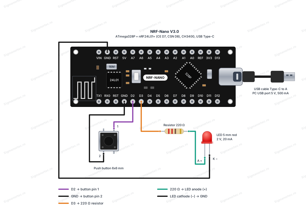
We will build a radio test with two identical boards. Each board has a button and an LED connected, and each board sends the state of its button and lights the LED of the other board. Power and programming are done through USB Type-C from the computer.

How it works:
The board has two parts that work together. The ATmega328P microcontroller runs the program, and the nRF24L01+ radio transmits and receives packets in the 2.4 GHz band. The two communicate over SPI, with CE on D7, CSN on D8, MOSI on D11, MISO on D12 and SCK on D13. For this reason, these five pins cannot be used for anything else.
The radio works on channels spaced 1 MHz apart, numbered from 0 to 125. The frequency of a channel is calculated as follows: frequency = 2400 MHz + channel number. For channel 76 used in the program, the result is 2400 + 76 = 2476 MHz. Both boards must use the same channel and the same data rate.
Each board has a 5-byte address. Board A sends to the address of board B and listens on its own address. Board B does the opposite. The radio uses automatic packet acknowledgement, so the write() function returns true only if the other board received the packet. A packet can have at most 32 bytes, and we send a single byte with the button state.
The button is read with INPUT_PULLUP. The internal resistor connects the pin to 5 V, and when pressed, the button connects it to GND, so the reading is LOW when the button is pressed. The LED has a 220 ohm resistor in series. The current through the LED is approximately (5 V - 2 V) / 220 ohms = 14 mA, well below the 40 mA limit of a pin.
Connection:
Power the board through USB Type-C from a USB port of the computer, at 5 V. The board logic is 5 V, and the radio is powered internally at 3.3 V by the regulator on the board, so no level converter and no separate power supply for the radio are needed. Mount the same components on both boards.
| Product pin | Connect to | Role |
|---|---|---|
| USB Type-C | USB port of the computer (USB-A to USB Type-C cable) | 5 V power and programming |
| D2 | 6x6 mm button, pin 1 | Input with INPUT_PULLUP, reads LOW when pressed |
| GND | 6x6 mm button, pin 2 | Button ground |
| D3 | 220 ohm resistor, end 1 | Digital output for the LED |
| 220 ohm resistor, end 2 | 5 mm red LED, anode (long leg) | LED current limiting |
| GND | 5 mm red LED, cathode (short leg) | LED ground |
Buttons, adjustments and indicators:
| Element | What it does | How to use it |
|---|---|---|
| RESET button | Resets the ATmega328P microcontroller | Press briefly to restart the program from the beginning |
| Test LED D13 | Lights up when pin D13 is HIGH | Use it as an activity indicator on D13. Because D13 is the SCK line of the radio, in this program it can blink to show when the radio is working |
The RESET button has no long press function. Press it once after you have connected the assembly, and you will see the startup message on the serial monitor, which confirms that the program has restarted.
The test LED on D13 requires no adjustment. In this tutorial we do not control it from the program, and it may blink slightly because D13 carries the SPI clock of the radio. This is normal.
The button on D2 and the LED on D3 are the components you mounted. Startup is done with the button released (HIGH reading) and the LED off. When the button is pressed on one board, the LED on the other board must light up.
Board and libraries:
In Arduino IDE, select Tools > Board > Arduino AVR Boards > Arduino Nano. The Arduino AVR Boards package comes with Arduino IDE and does not need to be installed separately. Under Tools > Processor, select ATmega328P, and if the upload gives an error, select ATmega328P (Old Bootloader). Under Tools > Port, select the newly appeared serial port.
From the Library Manager, install the RF24 library by TMRh20, version 1.4.0 or newer. The SPI library comes with Arduino IDE and does not need to be installed.
The code:
The same program is uploaded to both boards. The only difference is the value of NODE_ID at the beginning, which is 0 for the first board and 1 for the second.
/*
  NRF-Nano V3.0 radio test: two boards, each sends its button state
  and lights the LED of the other board.
  Board in Arduino IDE: Arduino Nano (Tools > Board > Arduino AVR Boards > Arduino Nano)
  Processor: ATmega328P (if upload fails, use ATmega328P (Old Bootloader))
  Board package: Arduino AVR Boards (comes with Arduino IDE)
  Library to install from Library Manager: RF24 by TMRh20 (version 1.4.0 or newer)
  SPI library comes with Arduino IDE.
  Wiring on each board:
    D2  -> push button pin 1 (button pin 2 -> GND), INPUT_PULLUP
    D3  -> resistor 220 ohm -> LED anode (LED cathode -> GND)
  Built-in radio nRF24L01+: CE = D7, CSN = D8, MOSI = D11, MISO = D12, SCK = D13
  Upload this same sketch to both boards.
  Set NODE_ID to 0 for the first board and to 1 for the second board.
*/
#include <SPI.h>
#include <RF24.h>
// Identity of this board: 0 for the first board, 1 for the second board
#define NODE_ID 0
// Pin definitions
const uint8_t PIN_BUTTON = 2;   // Push button to GND, read with internal pull-up
const uint8_t PIN_LED = 3;      // LED through 220 ohm resistor
const uint8_t PIN_CE = 7;       // Radio CE pin on NRF-Nano V3.0
const uint8_t PIN_CSN = 8;      // Radio CSN pin on NRF-Nano V3.0
// Timing settings in milliseconds
const unsigned long SEND_INTERVAL_MS = 100;    // How often the button state is sent
const unsigned long LINK_TIMEOUT_MS = 1000;    // Link is lost after this time without packets
const unsigned long PRINT_INTERVAL_MS = 500;   // How often the status is printed
// Radio object
RF24 radio(PIN_CE, PIN_CSN);
// One address for each board (5 characters plus the end of string)
const byte addresses[][6] = {"NODE0", "NODE1"};
// State variables
uint8_t localState = 0;        // 1 when the local button is pressed
uint8_t remoteState = 0;       // 1 when the button of the other board is pressed
bool lastSendOk = false;       // Result of the last transmission
bool everReceived = false;     // True after the first packet is received
unsigned long lastSend = 0;
unsigned long lastReceive = 0;
unsigned long lastPrint = 0;
// Prints the current status on the serial monitor
void printStatus() {
  bool linkOk = everReceived && (millis() - lastReceive < LINK_TIMEOUT_MS);
  Serial.print(F("Local: "));
  Serial.print(localState ? F("PRESSED") : F("RELEASED"));
  Serial.print(F(" | Sent: "));
  Serial.print(lastSendOk ? F("OK") : F("FAILED"));
  Serial.print(F(" | Remote: "));
  Serial.print(remoteState ? F("PRESSED") : F("RELEASED"));
  Serial.print(F(" | Link: "));
  Serial.println(linkOk ? F("OK") : F("LOST"));
}
void setup() {
  // Start the serial monitor
  Serial.begin(9600);
  // Configure the button with pull-up and the LED as output
  pinMode(PIN_BUTTON, INPUT_PULLUP);
  pinMode(PIN_LED, OUTPUT);
  digitalWrite(PIN_LED, LOW);
  // Start the radio and stop if it does not answer
  if (!radio.begin()) {
    Serial.println(F("Radio not responding. Check CE and CSN pins."));
    while (true) {
      // Wait here forever
    }
  }
  // Radio settings, they must be the same on both boards
  radio.setPALevel(RF24_PA_LOW);   // Low power is enough for a bench test
  radio.setChannel(76);            // 2400 + 76 = 2476 MHz
  // This board writes to the other board and listens on its own address
  const uint8_t ownIndex = NODE_ID;
  const uint8_t peerIndex = 1 - NODE_ID;
  radio.openWritingPipe(addresses[peerIndex]);
  radio.openReadingPipe(1, addresses[ownIndex]);
  // Listen by default
  radio.startListening();
  Serial.print(F("Radio ready on channel 76, node "));
  Serial.println(NODE_ID);
}
void loop() {
  unsigned long now = millis();
  // Read the button and send its state at a fixed interval
  if (now - lastSend >= SEND_INTERVAL_MS) {
    lastSend = now;
    localState = (digitalRead(PIN_BUTTON) == LOW) ? 1 : 0;  // LOW means pressed
    radio.stopListening();                                   // Switch to transmit mode
    lastSendOk = radio.write(&localState, sizeof(localState));
    radio.startListening();                                  // Back to receive mode
  }
  // Read every packet that arrived
  while (radio.available()) {
    radio.read(&remoteState, sizeof(remoteState));
    lastReceive = millis();
    everReceived = true;
  }
  // Turn the LED on only while the link is alive and the remote button is pressed
  bool linkOk = everReceived && (millis() - lastReceive < LINK_TIMEOUT_MS);
  digitalWrite(PIN_LED, (linkOk && remoteState) ? HIGH : LOW);
  // Print the status from time to time
  if (now - lastPrint >= PRINT_INTERVAL_MS) {
    lastPrint = now;
    printStatus();
  }
}
How the code works:
At the beginning we define NODE_ID, the pins PIN_BUTTON (D2), PIN_LED (D3), PIN_CE (D7) and PIN_CSN (D8), as well as the time intervals SEND_INTERVAL_MS, LINK_TIMEOUT_MS and PRINT_INTERVAL_MS. The radio object is created with RF24 radio(PIN_CE, PIN_CSN), and the addresses array contains the addresses of the two boards.
In setup() we start the serial port at 9600 baud, configure the button with INPUT_PULLUP and the LED as an output, then start the radio with radio.begin(). If the radio does not respond, the program displays a message and stops. Then we set channel 76, the power level RF24_PA_LOW, the writing address of the other board with openWritingPipe() and our own reading address with openReadingPipe(). Finally we call startListening(), so the board listens by default.
In loop() we send the button state every SEND_INTERVAL_MS. First we read the button into the localState variable, which is 1 if the button is pressed. We stop listening with stopListening(), send the byte with write(), store the result in lastSendOk and resume listening.
As long as radio.available() is true, we read the packet into remoteState and store the moment of reception in lastReceive. The LED on D3 follows the remoteState, and if nothing is received for more than LINK_TIMEOUT_MS, the LED turns off as a safety measure. Every PRINT_INTERVAL_MS, the printStatus() function displays the state of the local button, the result of the transmission, the state of the button on the other board and the state of the link.
Result:
Open Tools > Serial Monitor and set the speed to 9600 baud. After startup, the two boards display their status every half second. When you press the button on one board, the LED on the other lights up, and the line on the serial monitor shows RELEASED or PRESSED.
Radio ready on channel 76, node 0
Local: RELEASED | Sent: FAILED | Remote: RELEASED | Link: LOST
Local: RELEASED | Sent: OK | Remote: RELEASED | Link: OK
Local: RELEASED | Sent: OK | Remote: RELEASED | Link: OK
Local: PRESSED | Sent: OK | Remote: RELEASED | Link: OK
Local: PRESSED | Sent: OK | Remote: RELEASED | Link: OK
Local: RELEASED | Sent: OK | Remote: PRESSED | Link: OK
Local: RELEASED | Sent: OK | Remote: PRESSED | Link: OK
Local: RELEASED | Sent: OK | Remote: RELEASED | Link: OK
Common problems:
The board does not appear as a serial port. The cause is usually a cable that only charges, or the CH340 driver. Use a USB-A to USB Type-C cable with data transfer, and if the port still does not appear, install the driver from the Download section, because the latest version from 2023 may be incompatible with the board.
The upload stops with the error avrdude not in sync. The board has an older bootloader. Under Tools > Processor, select the ATmega328P (Old Bootloader) option and upload again.
The serial monitor shows a message that the radio does not respond. Check that you are using RF24 radio(7, 8), which is correct for V3.0. The older RF-Nano V1 and V2 boards use CE on D10 and CSN on D9, so for them try RF24 radio(10, 9). Also check that you have not connected anything to D7, D8, D11, D12 or D13.
The link state is always LOST. Check that NODE_ID is different on the two boards (0 and 1), that both use channel 76 and that both are powered. Bring the boards a few meters closer and move them away from metal objects.
The LED is always off or always on. Check the polarity of the LED (anode toward the resistor) and that the button is mounted across the diagonal, with one pin to D2 and the other to GND. With INPUT_PULLUP, the button must read LOW only when it is pressed.
The radio stops or resets randomly. The radio is sensitive to unstable power. Use a direct USB port of the computer or a good power source, not a weakly powered hub.
Limitations and tips:
Pins D7, D8, D11, D12 and D13 are occupied by the radio, so for sensors the free pins are D2 - D6, A0 - A7 (A6 and A7 are analog inputs only) and the serial pins D0 and D1. Each I/O pin supports at most 40 mA, so relays and motors should be driven through transistors or dedicated modules.
A radio packet has at most 32 bytes, and the range depends on the environment, on obstacles and on the power level set. The RF24_PA_LOW power is sufficient for bench tests, and for longer distances you can increase the level with setPALevel(), provided the power supply is stable.
Starting from this setup, you can build a remote control with several buttons, a temperature sensor that sends values to a central board, or a star network in which one board receives on multiple addresses from several transmitters.