
Product images are for informational purposes only and may vary slightly depending on the batch and supplier. Product specifications and prices may be subject to change without notice. We do our best to provide accurate and complete product specifications, but they may not be completely accurate. If you encounter any such situation, please let us know.
The product is intended for specialists and requires qualified and authorized personnel. The product does not include assembly/use instructions . Putting the product into operation by unqualified persons leads to the loss of the warranty according to the Terms and Conditions on the site.
The specified technical parameters (current, power, etc.) represent maximum allowable values under ideal operating conditions. For safe use and optimal lifespan, it is recommended to operate the product continuously at no more than 50% of the specified maximum values.
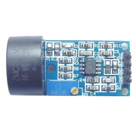
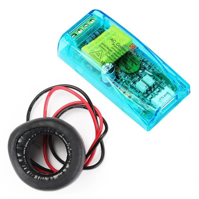
AC energy measurement module, PZEM-004T-100A, v3.0, 100A, TTL, 80–260V
The module for monitoring consumption on single-phase AC networks, ideal for automation and IoT projects, measures voltage 80-260VAC, current 0-100A with an external transformer, power, frequency, power factor, and energy up to 9999.99kWh, communicates Modbus-RTU via UART TTL 9600, and provides optocoupled isolation for safe integration with Arduino, ESP32, or PC.
Shipping by Thursday 22 October
Buying this product earns you 4.25 RON in loyalty points.

International fast shipping within EU. Free Shipping for orders above 100 EUR in most EU countries.

We ship from our stock within 24H

You earn points with every order, worth 5%.
The PZEM-004T-100A module is a multifunction meter for single-phase AC networks, designed for accurate monitoring of the electrical energy consumption of an installation or an individual device. It measures voltage, current, active power, power factor, frequency, and consumed active energy simultaneously. The data is read by a microcontroller or a computer through the TTL serial interface. The module has no built-in display and is intended for integration into monitoring systems, automation, and IoT projects.
Voltage is measured directly on the mains, in the 80 - 260VAC range, with a resolution of 0.1V. Current is measured using an external current transformer, in the 0 - 100A range, with a resolution of 0.001A and a minimum measurement threshold of 0.02A. Active power is calculated up to 23kW, with a resolution of 0.1W and a minimum measurement threshold of 0.4W. Consumed energy is counted up to 9999.99kWh, with a resolution of 1Wh, and the energy counter can be reset from software. Mains frequency is measured in the 45 - 65Hz range, with a resolution of 0.1Hz, and power factor between 0.00 and 1.00, with a resolution of 0.01. Accuracy is 0.5% for voltage, current, power, frequency, and energy, and 1% for power factor.
The module allows configuring an alarm threshold for active power. Exceeding the threshold is signaled through a status register that can be read by the controller. The measurement circuit is galvanically isolated from the TTL interface by optocouplers, which protects the connected development board.
Communication uses the Modbus-RTU protocol over the UART TTL interface, at 9600 baud, 8 data bits, 1 stop bit, and no parity (9600 8N1). For a single module, the default address 0xF8 is used. The Modbus address can be configured in the 0x01 - 0xF7 range, allowing up to 247 modules to be connected on the same serial bus. The module is compatible with Arduino Uno, Nano, and Mega, with ESP32 and ESP8266, and with USB-TTL adapters for direct reading on a PC. It can also be used with STM32, Raspberry Pi, or other UART-based platforms through a Modbus-RTU implementation. For quick integration, the dedicated PZEM004Tv30 library is available. The module is also supported by ESPHome and Home Assistant.
The TTL interface is passive. The 5V pin powers only the interface optocouplers, while the measurement circuit is powered from the 220VAC mains. For this reason, the module communicates only when connected to the mains and when all 4 wires of the TTL interface are connected. For boards with 3.3V logic (ESP32, ESP8266, STM32), a logic level converter or a resistor divider is recommended on the module’s TX line.
WARNING! The module connects directly to the 220VAC mains voltage, which can cause electric shock or death. Assembly and any intervention on the connections must be done only with the mains disconnected. Do not touch the board, terminals, or conductors while the module is energized. Use an insulated enclosure for the final assembly. If you do not have experience with electrical installations, contact a licensed electrician.
Specifications:
Model: PZEM-004T-100A (v3.0)
Type: Single-phase AC measuring module with communication interface
Measured voltage: 80 - 260VAC
Voltage resolution: 0.1V
Measured current: 0 - 100A (with external current transformer)
CT: Closed loop
Minimum measurement current: 0.02A
Current resolution: 0.001A
Active power: 0 - 23kW
Minimum measurement power: 0.4W
Power resolution: 0.1W
Power factor: 0.00 - 1.00
Power factor resolution: 0.01
Frequency: 45 - 65Hz
Frequency resolution: 0.1Hz
Active energy: 0 - 9999.99kWh
Energy resolution: 1Wh
Accuracy: 0.5% (voltage, current, power, frequency, energy)
Power factor accuracy: 1%
Power alarm: Configurable threshold
Protocol: Modbus-RTU
Interface: UART TTL, 9600 baud, 8N1
Default address: 0xF8 (single module)
Configurable addresses: 0x01 - 0xF7
TTL interface power supply: 5V (external, from the development board)
Isolation: Optocoupler between the measurement circuit and the TTL interface
Operating temperature: -20 ~ +40°C
Dimensions: 78 x 37 x 19mm
Layout:

Usage:
Disconnect the power supply before any assembly operation.
Connect the module’s L and N terminals to the phase and neutral of the mains.
Pass only the phase conductor through the current transformer. Do not pass phase and neutral together, because the currents cancel out and the module will indicate 0A.
Connect the transformer wires to the module’s CT input.
Connect the TTL interface to the development board as follows: 5V to 5V, GND to GND, module TX to board RX, and module RX to board TX. All 4 wires are mandatory.
For 3.3V logic boards, use a logic level converter on the module’s TX line.
Reconnect the mains. The module responds on the serial interface only if mains voltage is present between L and N.
Install the PZEM004Tv30 library in Arduino IDE and upload the test code.
Open Serial Monitor at 115200 baud to view the measured values.
If you get read errors and only the TX LED blinks, swap the RX and TX wires.
If the current value seems high compared to the load power, check the power factor. For loads with a low power factor, the relation P = U x I does not apply.

Pinout:
| Pin | Function |
|---|---|
| 5V | TTL interface optocoupler power supply (5 V from the board) |
| RX | Data reception – connect to the board’s TX |
| TX | Data transmission – connect to the board’s RX |
| GND | TTL interface ground |
| L | Mains phase 80–260 VAC |
| N | Mains neutral |
| CT | Current transformer input (2 wires) |
Modbus registers (read with function 0x04):
| Register | Description | Resolution |
|---|---|---|
| 0x0000 | Voltage | 0.1 V |
| 0x0001 | Current (lower 16 bits) | 0.001 A |
| 0x0002 | Current (upper 16 bits) | — |
| 0x0003 | Power (lower 16 bits) | 0.1 W |
| 0x0004 | Power (upper 16 bits) | — |
| 0x0005 | Energy (lower 16 bits) | 1 Wh |
| 0x0006 | Energy (upper 16 bits) | — |
| 0x0007 | Frequency | 0.1 Hz |
| 0x0008 | Power factor | 0.01 |
| 0x0009 | Alarm status | 0xFFFF – alarm; 0x0000 – normal |
Dimension diagram:

Library link:
- Nominal Current
- 100 A
- Input Voltage
- 80 - 260 V
- Input Voltage Type
- AC
- Model
- PZEM-004T-100A v3.0
- Communication interface
- TTL
Produs destinat utilizarii in proiecte electronice, automatizari, prototipare, educatie si cercetare.
Produsul trebuie utilizat numai conform specificatiilor tehnice mentionate in descriere si/sau in documentatia produsului.
Avertismente generale de siguranta:
Nu utilizati produsul la tensiuni, curenti sau temperaturi peste valorile specificate.
Montajul si conectarea trebuie realizate de persoane cu cunostinte tehnice minime in domeniul electric/electronic.
Evitati scurtcircuitele, inversarea polaritatii si conectarea gresita a alimentarii.
Nu lasati produsul alimentat nesupravegheat in timpul testelor.
Produsul nu este jucarie si nu este destinat copiilor.
Pentru modulele electronice, se recomanda utilizarea in carcase, panouri sau montaje protejate, dupa caz.
Identificare produs:
Denumirea produsului, codul/SKU-ul si caracteristicile tehnice sunt mentionate in pagina produsului si/sau pe eticheta ambalajului.
Producator / Importator / Distribuitor:
Sigmanortec S.R.L.
Calea Bucuresti nr. 9, Targu Jiu, Gorj, Romania
E-mail: [email protected]
Website: www.sigmanortec.ro
Persoana responsabila in UE:
Sigmanortec S.R.L.
Calea Bucuresti nr. 9, Targu Jiu, Gorj, Romania
E-mail: [email protected]
Documentatie si siguranta:
Pentru informatii suplimentare, fise tehnice, declaratii de conformitate sau instructiuni, ne puteti contacta la [email protected].
// PZEM-004T v3.0 test sketch
// Library: PZEM004Tv30 by Jakub Mandula
// Arduino Uno/Nano: SoftwareSerial on pins 11 (RX) and 12 (TX)
// ESP32: Serial2 on pins 16 (RX) and 17 (TX)
// Wiring: PZEM TX -> board RX pin, PZEM RX -> board TX pin
// The PZEM must be connected to mains voltage to communicate
#include <PZEM004Tv30.h>
#if defined(ESP32)
#define PZEM_RX_PIN 16
#define PZEM_TX_PIN 17
PZEM004Tv30 pzem(Serial2, PZEM_RX_PIN, PZEM_TX_PIN);
#else
#include <SoftwareSerial.h>
#define PZEM_RX_PIN 11
#define PZEM_TX_PIN 12
SoftwareSerial pzemSWSerial(PZEM_RX_PIN, PZEM_TX_PIN);
PZEM004Tv30 pzem(pzemSWSerial);
#endif
void setup() {
Serial.begin(115200);
Serial.println("PZEM-004T v3.0 test");
// Uncomment to reset the internal energy counter
// pzem.resetEnergy();
}
void loop() {
float voltage = pzem.voltage();
float current = pzem.current();
float power = pzem.power();
float energy = pzem.energy();
float frequency = pzem.frequency();
float pf = pzem.pf();
if (isnan(voltage)) {
Serial.println("Error reading PZEM (check wiring and mains voltage)");
} else {
Serial.print("Voltage: "); Serial.print(voltage, 1); Serial.println(" V");
Serial.print("Current: "); Serial.print(current, 3); Serial.println(" A");
Serial.print("Power: "); Serial.print(power, 1); Serial.println(" W");
Serial.print("Energy: "); Serial.print(energy, 3); Serial.println(" kWh");
Serial.print("Frequency: "); Serial.print(frequency, 1); Serial.println(" Hz");
Serial.print("PF: "); Serial.println(pf, 2);
}
Serial.println();
delay(2000);
}