
Product images are for informational purposes only and may vary slightly depending on the batch and supplier. Product specifications and prices may be subject to change without notice. We do our best to provide accurate and complete product specifications, but they may not be completely accurate. If you encounter any such situation, please let us know.
The product is intended for specialists and requires qualified and authorized personnel. The product does not include assembly/use instructions . Putting the product into operation by unqualified persons leads to the loss of the warranty according to the Terms and Conditions on the site.
The specified technical parameters (current, power, etc.) represent maximum allowable values under ideal operating conditions. For safe use and optimal lifespan, it is recommended to operate the product continuously at no more than 50% of the specified maximum values.
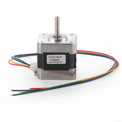
Stepper Motor, NEMA17, 1.7A, 1.8°, 42x42x40mm, Bipolar
Stepper motor for precise axis drive on 3D printers and CNC routers, compatible with A4988 and DRV8825 drivers. Offers 1.8 degree step for fine control, 1.7A current per phase with 2 phases for stable torque, 40N.cm holding force for secure positioning, compact 42x42x40mm format suitable for integration into standard assemblies.
Shipping by Thursday 22 October
Buying this product earns you 2.90 RON in loyalty points.

International fast shipping within EU. Free Shipping for orders above 100 EUR in most EU countries.

We ship from our stock within 24H

You earn points with every order, worth 5%.
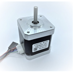
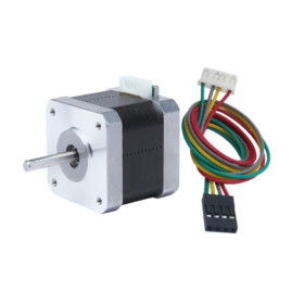
The NEMA 17 JK42HS40-1704 stepper motor is a 2-phase bipolar hybrid motor. It is used for moving axes on 3D printers, CNC routers, laser engravers, and other linear positioning systems. It has a step angle of 1.8 degrees, meaning 200 steps per revolution, and a holding torque of 4.2kg.cm (approx. 41N.cm). This provides precise and repeatable motion, without position sensors.
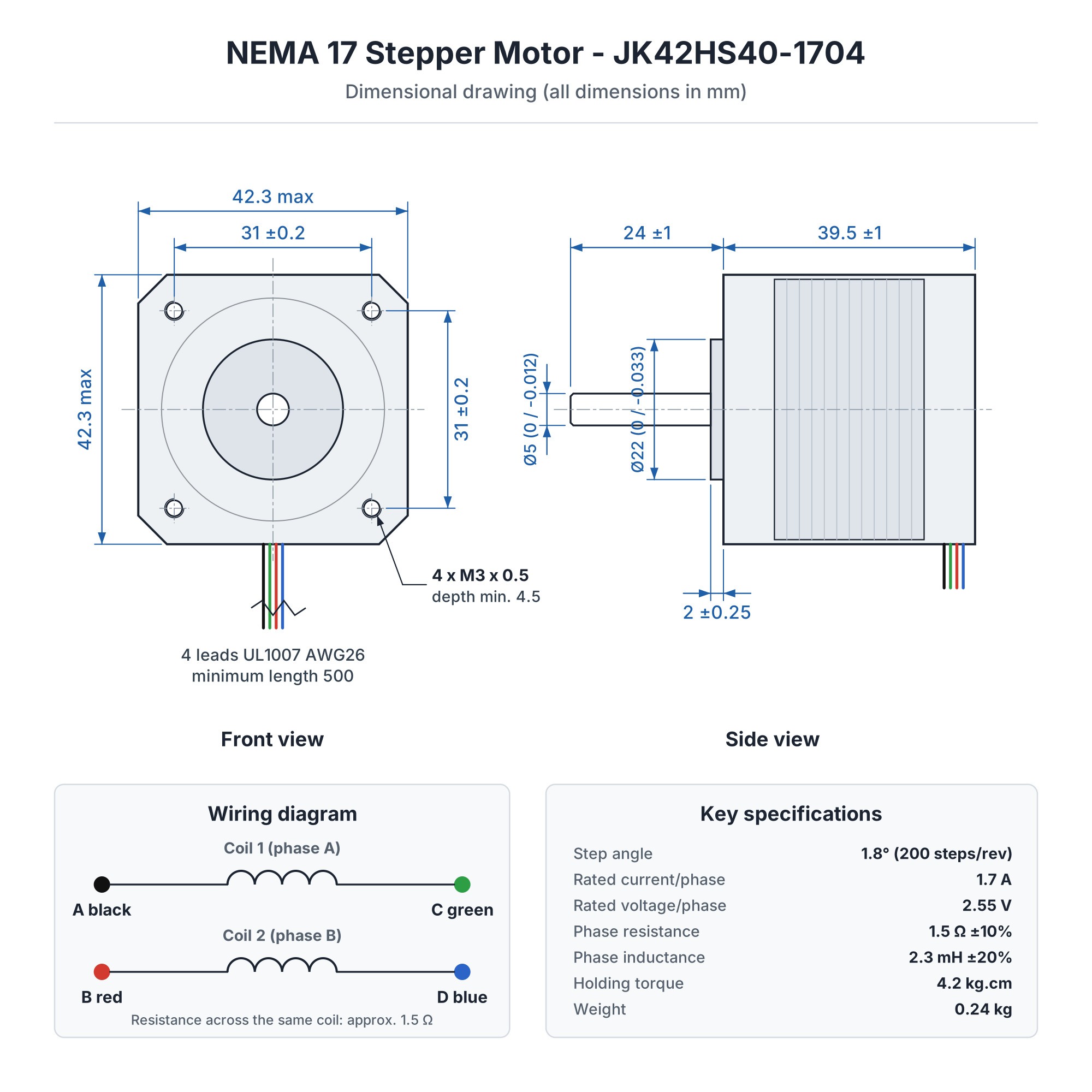
The body is 39.5mm long and has a standard NEMA 17 flange measuring 42.3 x 42.3mm. The flange has 4 threaded M3 holes spaced 31mm apart and a 22mm centering collar, so the motor fits most mounts and parts for 3D printers and CNC machines. The shaft has a diameter of 5mm and a length of 24mm. It is suitable for GT2 pulleys, 5 x 8mm flexible couplings for T8 lead screws, or extruder mechanisms. The motor has 4 UL1007 AWG26 wires with a minimum length of 500mm.
The rated current is 1.7A per phase, and the coil resistance is low (1.5Ω). Therefore, the motor is used with current-controlled drivers such as A4988, DRV8825, TMC2208, or TMC2209, powered at 12 - 24VDC. It is compatible with Arduino Uno with CNC Shield V3 and Arduino Mega with RAMPS 1.4. It also works with 3D printer boards running Marlin or Klipper firmware, with GRBL controllers, and with ESP32, STM32, or Raspberry Pi platforms, through a driver.
Specifications:
Model: JK42HS40-1704
Motor type: 2-phase bipolar hybrid
Step angle: 1.8 degrees (200 steps/revolution)
Rated phase current: 1.7A
Rated phase voltage: 2.55V
Phase resistance: 1.5Ω ±10% (at 20°C)
Phase inductance: 2.3mH ±20% (1kHz, 1V RMS)
Holding torque: 4.2kg.cm (approx. 41N.cm)
Insulation class: B (130°C)
Temperature rise: max. 80K at rated current
Number of wires: 4 (UL1007 AWG26)
Wire length: min. 500mm
Recommended driver supply voltage: 12 - 24VDC
Body dimensions: 42.3 x 42.3 x 39.5mm
Shaft: Ø5mm x 24mm, with flat, D-shape
Centering collar: Ø22mm x 2mm
Mounting holes: 4 x M3 x 0.5, min. depth 4.5mm, spacing 31mm
Weight: 0.24kg
Pinout:
| Wire | Color | Function | A4988 Pin | DRV8825 Pin |
|---|---|---|---|---|
| A | Black | Coil 1 (A+) | 1A | A1 |
| C | Green | Coil 1 (A-) | 1B | A2 |
| B | Red | Coil 2 (B+) | 2A | B1 |
| D | Blue | Coil 2 (B-) | 2B | B2 |
Step Sequence:
Full-step command sequence, viewed from the flange side. Steps 1 to 4 give clockwise direction (CW), and steps 4 to 1 give counterclockwise direction (CCW).
| Step | A | B | C | D |
|---|---|---|---|---|
| 1 | + | + | - | - |
| 2 | - | + | + | - |
| 3 | - | - | + | + |
| 4 | + | - | - | + |
Dimensions:
Usage:
Mount the motor on a bracket with 4 M3 screws. Choose the screw length so that they do not enter more than 4.5mm into the motor body.
Attach the GT2 pulley, coupling, or extruder gear to the shaft and tighten the locking screw firmly.
Identify the coil pairs. The black and green wires form coil 1, and the red and blue wires form coil 2. If in doubt, measure with a multimeter: between the ends of the same coil you should read approx. 1.5Ω.
Connect coil 1 to outputs 1A and 1B (A4988) or A1 and A2 (DRV8825). Connect coil 2 to 2A and 2B (A4988) or B1 and B2 (DRV8825).
Adjust the driver current limit using the potentiometer before first startup. For the DRV8825, use the formula Vref = I / 2. For the A4988, the formula is Vref = I x 8 x Rs, so for Rs = 0.1Ω (R100 marking) the result is Vref = I x 0.8. For continuous operation, 1.2 - 1.5A is recommended, without exceeding 1.7A.
Power the driver at 12 - 24VDC from a supply that can provide the required current for all motors. Install a capacitor of at least 100uF on the driver power supply.
Connect the STEP, DIR, and EN pins of the driver to the control board (Arduino, ESP32, STM32, or 3D printer board).
Set the number of steps per revolution in firmware: 200 for full-step, 3200 for 1/16 microstep (A4988), or 6400 for 1/32 microstep (DRV8825).
Do not connect or disconnect the motor while the driver is powered, as the driver may be damaged.
If the motor rotates in the wrong direction, reverse the wires of one coil or change the direction in firmware. If the motor vibrates without rotating, check the coil pairs.
It is normal for the motor to heat up during operation, with its temperature potentially rising by up to 80 degrees above ambient. Ensure good ventilation and reduce the current if the motor becomes too hot.
- Nominal Current
- 1.7 A
Produs destinat utilizarii in proiecte electronice, automatizari, prototipare, educatie si cercetare.
Produsul trebuie utilizat numai conform specificatiilor tehnice mentionate in descriere si/sau in documentatia produsului.
Avertismente generale de siguranta:
Nu utilizati produsul la tensiuni, curenti sau temperaturi peste valorile specificate.
Montajul si conectarea trebuie realizate de persoane cu cunostinte tehnice minime in domeniul electric/electronic.
Evitati scurtcircuitele, inversarea polaritatii si conectarea gresita a alimentarii.
Nu lasati produsul alimentat nesupravegheat in timpul testelor.
Produsul nu este jucarie si nu este destinat copiilor.
Pentru modulele electronice, se recomanda utilizarea in carcase, panouri sau montaje protejate, dupa caz.
Identificare produs:
Denumirea produsului, codul/SKU-ul si caracteristicile tehnice sunt mentionate in pagina produsului si/sau pe eticheta ambalajului.
Producator / Importator / Distribuitor:
Sigmanortec S.R.L.
Calea Bucuresti nr. 9, Targu Jiu, Gorj, Romania
E-mail: [email protected]
Website: www.sigmanortec.ro
Persoana responsabila in UE:
Sigmanortec S.R.L.
Calea Bucuresti nr. 9, Targu Jiu, Gorj, Romania
E-mail: [email protected]
Documentatie si siguranta:
Pentru informatii suplimentare, fise tehnice, declaratii de conformitate sau instructiuni, ne puteti contacta la [email protected].
Reviews (2) - Review moderation

/*
  Board: Arduino Uno (Arduino AVR Boards)
  Driver: A4988 Stepper Motor Driver
  Motor under test: NEMA17 stepper motor JK42HS40-1704, bipolar, 1.8 deg/step (200 steps/rev)

  Wiring:
    A4988 STEP   -> Arduino D3
    A4988 DIR    -> Arduino D2
    A4988 ENABLE -> Arduino D4
    A4988 VDD    -> Arduino 5V
    A4988 GND (logic) -> Arduino GND
    A4988 1A / 1B -> Motor coil A (black / green)
    A4988 2A / 2B -> Motor coil B (red / blue)
    A4988 VMOT   -> External 12-24V power supply (+)
    A4988 GND (power) -> External power supply GND

  Libraries: none required, uses only the built in digitalWrite and delayMicroseconds functions

  This sketch is a quick functional test: it steps the motor slowly for one
  revolution in each direction while printing a step counter, then disables
  the driver outputs briefly so you can check that the shaft turns freely
  (confirming the driver is really releasing the coils) before re-enabling it.
*/

const int stepPin = 3;
const int dirPin = 2;
const int enablePin = 4;
const int stepsPerRevolution = 200;
const int testStepDelayMicros = 2000;

void doStep() {
  digitalWrite(stepPin, HIGH);
  delayMicroseconds(testStepDelayMicros);
  digitalWrite(stepPin, LOW);
  delayMicroseconds(testStepDelayMicros);
}

void setup() {
  Serial.begin(9600);
  pinMode(stepPin, OUTPUT);
  pinMode(dirPin, OUTPUT);
  pinMode(enablePin, OUTPUT);
  digitalWrite(enablePin, LOW);
  Serial.println("A4988 + NEMA17 test start");
}

void loop() {
  Serial.println("Test: one revolution clockwise, slow speed");
  digitalWrite(dirPin, HIGH);
  for (int i = 1; i <= stepsPerRevolution; i++) {
    doStep();
    if (i % 50 == 0) {
      Serial.print("Step count: ");
      Serial.println(i);
    }
  }

  Serial.println("Test: one revolution counterclockwise, slow speed");
  digitalWrite(dirPin, LOW);
  for (int i = 1; i <= stepsPerRevolution; i++) {
    doStep();
    if (i % 50 == 0) {
      Serial.print("Step count: ");
      Serial.println(i);
    }
  }

  Serial.println("Disabling driver outputs for 2 seconds, shaft should turn freely by hand");
  digitalWrite(enablePin, HIGH);
  delay(2000);
  digitalWrite(enablePin, LOW);
  Serial.println("Driver re-enabled, holding torque restored");
  delay(1000);
}
The NEMA17 JK42HS40-1704 stepper motor is a bipolar hybrid motor with 4 wires, used for axis movement in 3D printers, CNC routers, laser engravers and other linear positioning systems where precise, step-based rotation is needed, without a position sensor.
To work, it absolutely needs a driver with current control, for example A4988, and a microcontroller that generates the step pulses. In this tutorial we use an Arduino Uno R3 board and an A4988 driver, the most commonly used combination for this type of motor in 3D printing and CNC projects.

How it works:
The motor has a step angle of 1.8 degrees, meaning 360 divided by 1.8 results in 200 steps for a full rotation, when driven in full step mode. Each pulse applied to the STEP pin of the driver makes the coils switch to another polarity combination, the rotor advancing by a single step.
The rotation speed is given by the frequency of the STEP pulses. The formula is frequency in Hz equals speed in RPM multiplied by the number of steps per rotation, all divided by 60. For example, for 60 RPM in full step mode, this results in 60 x 200 divided by 60, that is 200 Hz, so a STEP pulse every 5 ms.
The A4988 driver also allows microstepping, meaning it divides each full step into substeps, for example at 1/16 microstep this results in 200 x 16, that is 3200 steps per rotation, for a finer and quieter movement.
The current through the coils is limited from the potentiometer on the driver, following the formula Vref equals the desired current multiplied by 8 and by the sense resistor Rs. For an Rs of 0.1 ohm, marked R100 on most A4988 boards, the formula becomes Vref equals the current multiplied by 0.8. For this motor, with a rated current of 1.7 A, a limit of 1.2 to 1.5 A is recommended for long-term operation, that is a Vref between 0.96 and 1.2 V.
What you need:
- 1 x NEMA17 Stepper Motor 1.7A 1.8 degrees 42x42x40mm Bipolar
- 1 x Uno R3 Development Board with ESP8266 Wifi, Arduino compatible
- 1 x A4988 Stepper Driver + Heatsink
- 1 x 12V, 2A Power Supply
- 1 x 100uF Electrolytic Capacitor
- 1 x 40 Dupont Wires 10cm, Female-Female
- 1 x Breadboard 830 points MB-102
Wiring:
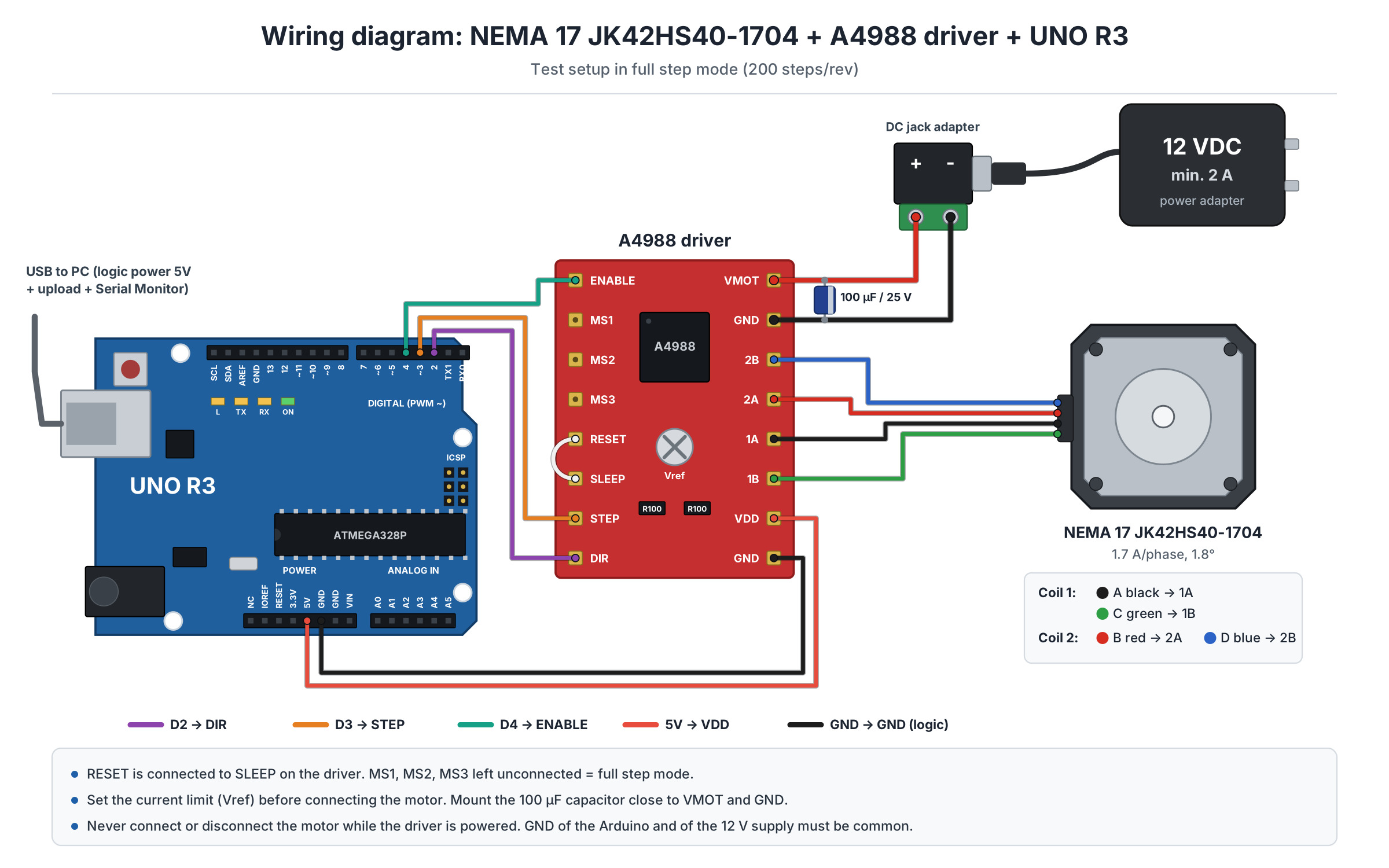
The motor is connected to the coil outputs of the A4988 driver, and the driver is connected to Arduino for the control signals and separately to an external 12 - 24 VDC power source for powering the motor.
| Product pin | Connects to | Role |
|---|---|---|
| A (black) | A4988 1A | Coil 1, + terminal |
| C (green) | A4988 1B | Coil 1, - terminal |
| B (red) | A4988 2A | Coil 2, + terminal |
| D (blue) | A4988 2B | Coil 2, - terminal |
The driver is powered separately on VMOT and GND with 12 - 24 VDC from an external source, not from Arduino, while VDD and logic GND are connected to 5V and GND on the Arduino. STEP is connected to D3, DIR to D2, and ENABLE to D4. The motor power wires work at a voltage higher than 5V, so they should never be connected directly to the Arduino pins. Install an electrolytic capacitor of at least 100 uF between VMOT and GND, as close as possible to the driver.
Board and libraries:
In Arduino IDE select the Arduino Uno board from the Arduino AVR Boards package, which comes included by default with Arduino IDE and does not require an additional URL in Preferences. The program only uses the standard digitalWrite and delayMicroseconds functions, so you do not need to install any library.
The code:
The code rotates the motor one full rotation clockwise, then one full rotation counterclockwise, repeating the cycle and displaying each stage on the serial monitor.
/*
  Board: Arduino Uno (Arduino AVR Boards)
  Driver: A4988 Stepper Motor Driver
  Motor: NEMA17 stepper motor JK42HS40-1704, bipolar, 1.8 deg/step (200 steps/rev)
  Wiring:
    A4988 STEP   -> Arduino D3
    A4988 DIR    -> Arduino D2
    A4988 ENABLE -> Arduino D4
    A4988 VDD    -> Arduino 5V
    A4988 GND (logic) -> Arduino GND
    A4988 1A / 1B -> Motor coil A (black / green)
    A4988 2A / 2B -> Motor coil B (red / blue)
    A4988 VMOT   -> External 12-24V power supply (+)
    A4988 GND (power) -> External power supply GND
  Libraries: none required, uses only the built in digitalWrite and delayMicroseconds functions
*/
const int stepPin = 3;
const int dirPin = 2;
const int enablePin = 4;
const int stepsPerRevolution = 200;
int stepDelayMicros = 1000;
void rotateSteps(int steps, bool clockwise) {
  digitalWrite(dirPin, clockwise ? HIGH : LOW);
  for (int i = 0; i < steps; i++) {
    digitalWrite(stepPin, HIGH);
    delayMicroseconds(stepDelayMicros);
    digitalWrite(stepPin, LOW);
    delayMicroseconds(stepDelayMicros);
  }
}
void setup() {
  Serial.begin(9600);
  pinMode(stepPin, OUTPUT);
  pinMode(dirPin, OUTPUT);
  pinMode(enablePin, OUTPUT);
  digitalWrite(enablePin, LOW);
  Serial.println("NEMA17 stepper motor ready");
}
void loop() {
  Serial.println("Rotating one full turn clockwise");
  rotateSteps(stepsPerRevolution, true);
  delay(1000);
  Serial.println("Rotating one full turn counterclockwise");
  rotateSteps(stepsPerRevolution, false);
  delay(1000);
}
How the code works:
At the beginning of the program the stepPin, dirPin and enablePin pins are defined, along with the number of steps per rotation stepsPerRevolution and the stepDelayMicros variable which controls the speed, a smaller delay meaning a higher speed.
In the setup function the pins are configured as outputs and the driver is enabled with digitalWrite on enablePin set to LOW, since A4988 has inverted enable logic, and serial communication starts at 9600 baud.
The rotateSteps function takes the number of steps and the direction, sets the dirPin pin according to the desired direction, then sends pulses on stepPin, each pulse consisting of a HIGH edge followed by a LOW edge, separated by the stepDelayMicros interval.
In the loop function, rotateSteps is called for a full rotation clockwise, then waits one second, then is called again for a full rotation counterclockwise, the cycle repeating indefinitely.
Result:
Open the serial monitor at 9600 baud. You will see the status messages, and the motor will visibly perform one full rotation in each direction, with a one second pause between them.
NEMA17 stepper motor ready
Rotating one full turn clockwise
Rotating one full turn counterclockwise
Rotating one full turn clockwise
Rotating one full turn counterclockwise
Rotating one full turn clockwise
Rotating one full turn counterclockwise
Common issues:
The motor vibrates but does not rotate: one of the coil pairs is wrong. Check with a multimeter that the black and green wires form one coil, and red and blue the other coil, and that each pair is connected to the same driver output (1A/1B, respectively 2A/2B).
The motor does not move at all: check that the driver is powered on VMOT with 12 - 24 VDC, that the ENABLE pin is LOW and that the GND wire of the external power source is common with the Arduino GND.
The motor loses steps or skips movements at high speed: the Vref current limit is too low for the load, or the requested speed is too high for the available torque. Slightly increase Vref, within the limit of 1.5 A, or reduce the speed by decreasing the stepDelayMicros value.
The driver or motor gets very hot: the current is set too close to 1.7 A without sufficient cooling. Install a heatsink on the A4988 and reduce Vref towards 1.2 A for long-term operation.
The motor rotates in the opposite direction from what you expect: swap the wires of a single coil, for example black with green, or change the value sent to dirPin in the code.
Limitations and tips:
The control is in open loop, without position feedback, so under too high a mechanical load the motor may lose steps without the driver or program knowing it. The available torque decreases as the rotation speed increases, so for fast applications a compromise is needed between speed and required torque. For quieter and finer movement you can replace the A4988 with a driver with finer microstepping, for example TMC2208 or TMC2209. Make sure the external power supply can provide the current needed for all motors connected simultaneously in a multi-axis system.