
Product images are for informational purposes only and may vary slightly depending on the batch and supplier. Product specifications and prices may be subject to change without notice. We do our best to provide accurate and complete product specifications, but they may not be completely accurate. If you encounter any such situation, please let us know.
The product is intended for specialists and requires qualified and authorized personnel. The product does not include assembly/use instructions . Putting the product into operation by unqualified persons leads to the loss of the warranty according to the Terms and Conditions on the site.
The specified technical parameters (current, power, etc.) represent maximum allowable values under ideal operating conditions. For safe use and optimal lifespan, it is recommended to operate the product continuously at no more than 50% of the specified maximum values.
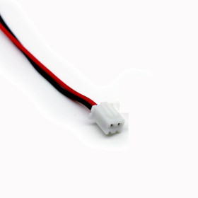
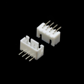
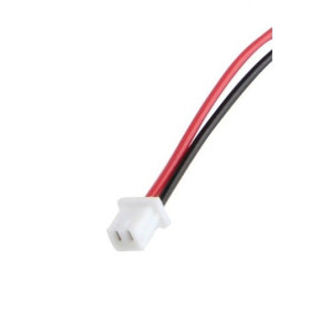
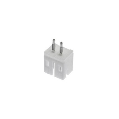
PH2.0 Female Connector, 2P, Straight, 2 mm Pitch
PH2.0 female connector with 2 straight pins, ideal for quick connections on PCBs and wiring in electronics projects. The 2 mm pin pitch ensures compatibility with the PH2.0 standard, and the 2P configuration provides a stable link in applications such as sensors, modules and signal power supplies.
Shipping by Wednesday 11 November
Buying this product earns you 0.03 RON in loyalty points.

International fast shipping within EU. Free Shipping for orders above 100 EUR in most EU countries.

We ship from our stock within 24H

You earn points with every order, worth 5%.
The PH2.0 connector with 2 positions and straight pins is a printed circuit board connector with a 2 mm pitch, used for detachable connections between an electronic board and a two-wire cable. The two-position plastic housing is soldered to the board through its two straight pins, and the cable connects through the PH2.0 plug with crimped terminals. It is suitable for low-voltage power supplies, sensor modules, small fans, small speakers, small batteries and any signal connection where the wire must be quickly removable from the board.
The PH2.0 series is designed for small currents and supports a rated current of 2 A per contact, with AWG 24 cable, at a rated voltage of 100 V. The contact resistance is at most 20 mΩ, so the voltage drop at currents on the order of hundreds of milliamps is only a few millivolts. The shape of the housing allows the plug to be inserted in only one direction, which helps avoid reversing the polarity.
The main features include the 2 mm pin spacing, the 2 positions, the straight pins for soldering into the board and the plastic housing that guides the plug during mating. The connector has no power supply of its own and no logic levels, it transmits the voltage and current of the circuit in which it is mounted.
Specifications:
Rated voltage: 100 V AC/DC
Rated current: 2 A per contact (AWG 24 cable)
Connector type: PH2.0
Number of positions: 2
Pin pitch: 2 mm
Pin type: Straight
Mounting: Through-hole soldering, board thickness 0.8 - 1.6 mm
Contact resistance: Maximum 20 mΩ
Operating temperature: -25 °C - +85 °C
Usage:
Choose the orientation of the connector on the board and determine which pin is positive and which is ground, then note your choice on the silkscreen or in the schematic, because the connector does not electrically mark the polarity.
Insert the pins into the holes of the board until the housing rests on the surface of the board, without tilting, so that the plug enters in the correct direction.
Solder one pin first, check that the base of the connector sits flat on the board and correct the position if needed, then solder the second pin. Use a soldering iron at approximately 330 - 350 °C and keep the tip on the pin for only 2 - 3 seconds, so that the plastic does not deform.
Prepare the cable with PH2.0 crimped terminals using a suitable crimping tool and insert the terminals into the 2-position housing until they lock, using wires within the range specified for the chosen terminal.
Before powering up, check with a multimeter in continuity mode that the wires reach the designated pins, then mate the plug holding it straight and pressing evenly until it is fully seated.
Do not exceed 2 A per contact and do not use the connector at the 220 VAC mains voltage or for motors and high loads.
To disconnect, pull the plug, not the wires, because the crimped terminals may come loose.
- Type
- Straight
- Operating temperature
- -25 °C - +85 °C
- Number of pins
- 2
- Connector type
- PH2.0
- Rated voltage
- 100 V AC/DC
- Mounting
- Solder mount on PCB, board thickness 0.8-1.6 mm
- Rated current
- 2 A pe contact (cablu AWG 24)
- Pin pitch
- 2 mm
- Contact resistance
- Maxim 20 mΩ
Produs destinat utilizarii in proiecte electronice, automatizari, prototipare, educatie si cercetare.
Produsul trebuie utilizat numai conform specificatiilor tehnice mentionate in descriere si/sau in documentatia produsului.
Avertismente generale de siguranta:
Nu utilizati produsul la tensiuni, curenti sau temperaturi peste valorile specificate.
Montajul si conectarea trebuie realizate de persoane cu cunostinte tehnice minime in domeniul electric/electronic.
Evitati scurtcircuitele, inversarea polaritatii si conectarea gresita a alimentarii.
Nu lasati produsul alimentat nesupravegheat in timpul testelor.
Produsul nu este jucarie si nu este destinat copiilor.
Pentru modulele electronice, se recomanda utilizarea in carcase, panouri sau montaje protejate, dupa caz.
Identificare produs:
Denumirea produsului, codul/SKU-ul si caracteristicile tehnice sunt mentionate in pagina produsului si/sau pe eticheta ambalajului.
Producator / Importator / Distribuitor:
Sigmanortec S.R.L.
Calea Bucuresti nr. 9, Targu Jiu, Gorj, Romania
E-mail: [email protected]
Website: www.sigmanortec.ro
Persoana responsabila in UE:
Sigmanortec S.R.L.
Calea Bucuresti nr. 9, Targu Jiu, Gorj, Romania
E-mail: [email protected]
Documentatie si siguranta:
Pentru informatii suplimentare, fise tehnice, declaratii de conformitate sau instructiuni, ne puteti contacta la [email protected].
Reviews (1) - Review moderation

Sunt conforme cu descrierea facuta si calitate pret ok.Multumesc!
The PH2.0 2-pin straight header is a printed circuit board connector with a 2 mm pitch, used for detachable connections between an electronic board and a two-wire cable. You will find it on sensor modules, on 3.3 V, 5 V or small battery power supplies, on small fans and speakers, anywhere the wire needs to be easy to disconnect from the board.
This tutorial uses the connector on its own, powered from a 5 V adapter, with no program and no other platform. We mount it, crimp the cable and power a 5 V sensor module.

How it works:
The connector has a plastic housing with two positions, 2 mm apart, and two straight metal pins that go into the holes of the board and are soldered. The other half of the connection is a PH2.0 2-position socket, which takes terminals crimped onto the ends of the wires. When the socket is inserted, each terminal presses on its pin and a stable electrical contact results, and the shape of the housing allows mating in only one direction.
The PH series is made for small currents. The rated current is 2 A per contact with AWG 24 wire, and the resistance of one contact is at most 20 mΩ. The voltage drop across a contact is calculated with U = I x R. At 2 A we get 2 A x 0.02 Ω = 0.04 V, that is 40 mV, and the dissipated power is P = I x U = 2 A x 0.04 V = 0.08 W. At 0.15 A the drop is only 0.15 A x 0.02 Ω = 3 mV. For this reason the connector is suitable for powering small modules and for signals, but not for motors or high-load devices.
Connection:
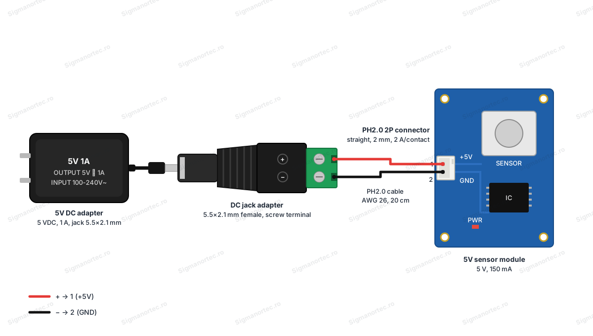
The connector has no power supply of its own and no logic levels. It passes on to the cable whatever it receives from the board, so the voltage and current are those of the circuit in which it is mounted. No level converters or pull-up resistors are needed. In our example, a 5 VDC adapter rated at 1 A powers, through a 5.5 x 2.1 mm jack adapter with screw terminals, a 5 V sensor module that draws 150 mA. The convention chosen is pin 1 = +5 V (red wire) and pin 2 = GND (black wire).
| Product pin | Connects to | Role |
|---|---|---|
| Pin 1 | The + terminal of the jack adapter, through the red wire, then to the 5 V input of the module | +5 V power supply |
| Pin 2 | The − terminal of the jack adapter, through the black wire, then to the GND of the module | Ground (GND) |
Configuration:
The connector has no buttons, jumpers, switches or LEDs. Preparing it means mounting it correctly on the board and respecting the same polarity convention on all boards and cables in the project. The parameters we need to keep in mind are given in the table.
| Parameter | Value |
|---|---|
| Pin pitch | 2 mm |
| Maximum current per contact | 2 A with AWG 24 cable |
| Rated voltage | 100 V |
| Board thickness | 0.8 - 1.6 mm |
| Board hole diameter | approximately 0.7 mm |
| Operating temperature | -25 °C - +85 °C, including the heating caused by the current |
Choose the orientation of the connector on the board and decide which pin is positive and which is ground. Note your choice on the silkscreen or in the schematic, because the housing does not mark the electrical polarity.
Insert the pins into the holes of the board until the housing sits on the surface of the board. The housing must be straight, without tilting, so that the socket enters in the correct direction.
First solder just one pin, check that the base of the connector sits flat on the board and correct the position if needed, then solder the second pin. Use a soldering iron at about 330 - 350 °C and keep the tip on the pin for only 2 - 3 seconds, so that the plastic does not deform.
Prepare the cable. Strip the end of the wire along the length of the terminal crimping zone, crimp the PH2.0 terminal with a suitable crimping tool and insert the terminal into the 2-position socket until it locks. Use wires within the range specified for the chosen terminal, usually AWG 24 - AWG 30.
Mate the socket with the connector, holding it straight and pressing evenly until it is fully seated. To disconnect, pull on the socket, not on the wires.
Usage example:
We power a 5 V sensor module that draws 150 mA through a 20 cm detachable cable. Set pin 1 as positive and pin 2 as ground. Solder the connector onto the module board, then crimp the positive terminal onto a red wire and the ground terminal onto a black wire, using AWG 26 wires, and insert them into the socket in the same order. The other ends of the wires connect to the + and − terminals of the jack adapter.
Before connecting the power supply, use the multimeter in continuity mode to check that the red wire reaches pin 1 and the black wire reaches pin 2. Mate the socket, then connect the 5 VDC adapter. At 150 mA the voltage drop across one contact is 0.15 A x 0.02 Ω = 3 mV, so the module receives practically the full 5 V. The result is correct when the module starts up and the voltage measured at its terminals is almost equal to that of the supply.
Common problems:
The module does not start after mating. The usual cause is a terminal that is not fully locked in the socket or a cold solder joint at a pin. Remove the socket, check that the terminals are at the same level, then reheat the solder joint and mate again.
The polarity is reversed. The wires were inserted into the socket in the wrong order, and the module does not work or gets hot. Disconnect the power immediately, remove the terminals from the socket with a fine needle, fit them in the correct order and check with the multimeter before powering again.
The contact is intermittent. The crimped terminal is too wide or the wire was crimped over the insulation. Redo the crimp with a new terminal, with the wire stripped to the right length.
The socket does not fit into the connector. The connector was soldered at an angle or the socket is turned the wrong way. Check the orientation of the socket against the shape of the housing and, if the base of the connector does not sit flat, unsolder it and mount it again.
The housing deformed during soldering. The soldering iron tip stayed on the pin too long or the temperature was too high. Solder briefly, at a lower temperature, and let the plastic cool before mating the socket.
Limitations and tips:
The connector is intended for small currents, up to 2 A per contact, and for low voltages. Do not use it at the 220 VAC mains voltage, nor for motors or loads that draw large currents. For higher loads, choose a connector with a larger pitch or with thicker contacts.
The connector has two positions, so it carries two conductors. For signals with more wires, use a PH2.0 variant with more positions. Longer cables or cables with a larger cross-section require suitable terminals, and a two-wire cable with PH2.0 connectors at both ends allows detachable connections between two boards.