Product images are for informational purposes only and may vary slightly depending on the batch and supplier. Product specifications and prices may be subject to change without notice. We do our best to provide accurate and complete product specifications, but they may not be completely accurate. If you encounter any such situation, please let us know.
The product is intended for specialists and requires qualified and authorized personnel. The product does not include assembly/use instructions . Putting the product into operation by unqualified persons leads to the loss of the warranty according to the Terms and Conditions on the site.
The specified technical parameters (current, power, etc.) represent maximum allowable values under ideal operating conditions. For safe use and optimal lifespan, it is recommended to operate the product continuously at no more than 50% of the specified maximum values.
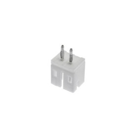
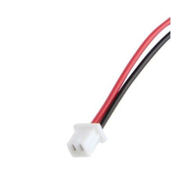
Micro JST Connector, PH2.0, 2P, Male, with 15cm Cable
Ideal for quickly making internal connections in electronic projects, providing secure and stable mating. Features a PH2.0 interface with 2 mm spacing, 2 pins for signal or power, a male version compatible with PH2.0 sockets, and a 15 cm cable for flexible mounting and neat wiring in tight spaces.
Buying this product earns you Ft7.58 in loyalty points.

International fast shipping within EU. Free Shipping for orders above 100 EUR in most EU countries.

We ship from our stock within 24H

You earn points with every order, worth 5%.
The Micro JST PH2.0 connector with 2 positions has a 15 cm cable with two wires, red and black, already attached to the housing. It is a passive accessory for powering or signal linking of modules, small batteries, speakers, LEDs and sensors that have a PH2.0 socket with 2 pins on the board. The free end of the wires can be soldered, clamped in a screw terminal, or extended with other wires.
The pin spacing is 2 mm, different from the 2.54 mm spacing of standard pin headers and breadboards. The white plastic housing contains two metal contacts attached to the ends of the wires and has a shape that allows insertion in only one direction, so the connector cannot be inserted rotated 180 degrees.
Among the main features are the 2-position PH2.0 housing, the 15 cm cable with two colored wires, the polarized housing and the 2 mm pin spacing. The connector has no power supply of its own, the voltage comes from the source or from the module it is connected to.
Specifications:
Rated voltage: 100 VAC/DC
Rated contact current: 2 A (AWG 24 wire)
Connector: PH2.0
Number of positions: 2
Pin spacing: 2 mm
Type: Male
Cable length: 15 cm
Wire colors: Red and black
Layout:
| Element | Function |
|---|---|
| White PH2.0 housing | Inserted onto the 2-pin PH2.0 socket on the board and fits in only one direction. |
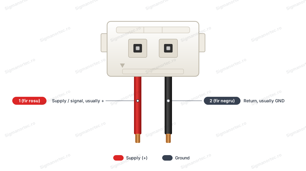
| Red wire | Connected to pin 1 of the housing, usually used for positive or signal. |
| Black wire | Connected to pin 2 of the housing, usually used for ground (GND). |
| Free end of the cable | Stripped, tinned and then soldered or clamped in a screw terminal. |
Pinout:
| Connector | Pin | Function |
|---|---|---|
| PH2.0 housing | 1 (red wire) | Power or signal, usually positive |
| PH2.0 housing | 2 (black wire) | Return, usually ground (GND) |
Usage:
Check that the socket on the board is of PH2.0 type, with two pins at 2 mm distance and the same number of positions as the housing.
Disconnect the power of the board and of the source before making any connection.
Strip the free ends of the wires by about 2 - 3 mm and tin them, so that the thin strands do not fray. Then solder them to the module or clamp them in a screw terminal.
The wire colors only show how the cable was assembled. Check the + and - markings next to the board socket and connect the wire that reaches the + pin of the socket to the positive terminal. On some boards the order is reversed compared to the colors.
Do not reverse the polarity and do not exceed the voltage allowed by the board or the consumer.
Insert the housing onto the socket straight, without twisting, until it stops. If it does not fit, do not force it and rotate the housing by 180 degrees.
Do not insert the housing onto a 2.54 mm pin header and do not force it into the holes of a breadboard, because this deforms the contacts.
Power on only after all connections are made and checked. Measure with a multimeter the voltage on the socket pins, which must match that of the source.
For thin cables, keep the current at about 1 A or less. Secure the cable with a cable tie or heat-shrink adhesive, so that it does not pull on the contacts.
- Type
- Male
- Colour
- Red and black
- Number of pins
- 2
- Cable length
- 15 cm
- Connector type
- PH2.0
- Rated voltage
- 100 V AC/DC
- Rated current
- 2 A (fir AWG 24)
- Pin pitch
- 2 mm
Produs destinat utilizarii in proiecte electronice, automatizari, prototipare, educatie si cercetare.
Produsul trebuie utilizat numai conform specificatiilor tehnice mentionate in descriere si/sau in documentatia produsului.
Avertismente generale de siguranta:
Nu utilizati produsul la tensiuni, curenti sau temperaturi peste valorile specificate.
Montajul si conectarea trebuie realizate de persoane cu cunostinte tehnice minime in domeniul electric/electronic.
Evitati scurtcircuitele, inversarea polaritatii si conectarea gresita a alimentarii.
Nu lasati produsul alimentat nesupravegheat in timpul testelor.
Produsul nu este jucarie si nu este destinat copiilor.
Pentru modulele electronice, se recomanda utilizarea in carcase, panouri sau montaje protejate, dupa caz.
Identificare produs:
Denumirea produsului, codul/SKU-ul si caracteristicile tehnice sunt mentionate in pagina produsului si/sau pe eticheta ambalajului.
Producator / Importator / Distribuitor:
Sigmanortec S.R.L.
Calea Bucuresti nr. 9, Targu Jiu, Gorj, Romania
E-mail: [email protected]
Website: www.sigmanortec.ro
Persoana responsabila in UE:
Sigmanortec S.R.L.
Calea Bucuresti nr. 9, Targu Jiu, Gorj, Romania
E-mail: [email protected]
Documentatie si siguranta:
Pentru informatii suplimentare, fise tehnice, declaratii de conformitate sau instructiuni, ne puteti contacta la [email protected].
Reviews (1) - Review moderation

Calitate buna si foarte utile in aplicatii.Multumesc!
The Micro JST PH2.0 connector with 2 pins and 15 cm cable is a passive accessory, with 2 mm spacing between pins. You use it to power or connect the signal of certain modules, small batteries, speakers, LEDs and sensors that have a PH2.0 socket on the board.
Being a part with no electronics and no program, the tutorial does not use any development board. It shows step by step how to check, prepare and use the connector, with an example where we power a 5 V module from a mains adapter.

How it works:
The white plastic housing contains two metal contacts attached to the ends of the wires. When inserted, the contacts grip the two pins of the socket on the board and close the electrical circuit on each wire. The shape of the housing allows insertion in only one direction.
The 2 mm spacing is different from the 2.54 mm spacing of standard pin headers and breadboards. The difference is 2.54 - 2 = 0.54 mm between the two pins, which is too large to fit by force. That is why you should not insert the housing onto a 2.54 mm pin header.
The wires have a low resistance, but not zero, and the voltage drop increases with length and with current. As an example, a AWG 24 copper wire has about 0.084 ohms per metre. For 15 cm this gives 0.084 x 0.15 = 0.0126 ohms per wire, that is about 0.025 ohms for the go and return path.
At a current of 1 A, the voltage drop is U = R x I = 0.025 x 1 = 0.025 V, so approximately 25 mV. For small loads, the loss is negligible.
The contacts of the JST PH series are rated for 2 A (AWG 24 wire) and 100 V. For a thin cable, a safe working limit is about 1 A or less.
Connection:
In the example we power a 5 V module with a PH2.0 socket from a 5 VDC mains adapter, minimum 2 A, with a 5.5 x 2.1 mm plug. Between the adapter and the cable we use a 5.5 x 2.1 mm DC jack female to screw terminal block adapter. The wires are connected to the + and - terminals marked on the body of the adapter, and the housing is inserted onto the module socket. The adapter usually has the positive at the centre, but check the symbol on it. Make all connections with the power supply disconnected from the mains.
| Product pin | Connect to | Role |
|---|---|---|
| Red wire (housing pin 1) | + terminal of the DC jack adapter with screw terminals | 5 V power supply, positive |
| Black wire (housing pin 2) | - terminal of the DC jack adapter with screw terminals | Return, ground (GND) |
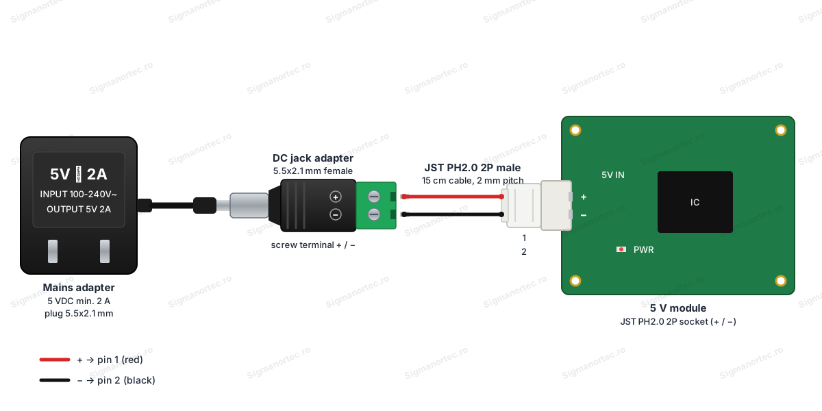
The wire colours only show how the cable was assembled. The correct polarity is that of the module socket, so check the + and - markings on the board before the first connection. On some sockets, for example on some sockets for LiPo batteries, the order is reversed. Do not exceed the voltage rating of the module.
Configuration:
The product has no buttons, jumpers, LEDs or display, so there are no settings to make. The preparation consists of choosing how to connect the free end and of checking the polarity. The parameters to keep in mind are in the table below.
| Parameter | Value | Why it matters |
|---|---|---|
| Connector type | PH2.0, 2 pins | It must be the same as the socket on the board. |
| Pin spacing | 2 mm | It does not fit on 2.54 mm pins. |
| Cable length | 15 cm | Determines the distance between the module and the power source or load. |
| Recommended current | At most about 1 A | The wires are thin, and the voltage drop and heating increase with current. |
Step 1. Check that the module socket is a PH2.0 type with two pins at 2 mm distance.
Step 2. Disconnect the mains adapter before making any connection.
Step 3. Strip the ends of the wires by about 2 - 3 mm and tin them with solder.
Step 4. Fix the red wire in the + terminal of the jack adapter and the black wire in the - terminal, then tighten the screws. Gently pull each wire to check that it is secured.
Step 5. If the module socket has the order reversed compared to the colours, connect the wires in reverse, so that the wire connected to positive reaches the pin marked + on the module.
Usage example:
Suppose you have a 5 V module with a PH2.0 socket marked + and -. With the adapter unplugged from the mains, connect the cable wires to the terminals of the DC jack adapter, according to the connection table. Insert the housing onto the module socket, straight, until it stops.
Connect the plug of the adapter to the jack and switch on the power supply. Measure the voltage on the socket pins with the multimeter before inserting the housing, to check that it is about 5 V. If the value is correct and the polarity matches the markings on the module, it starts normally.
If the value is zero or negative, switch off the power supply immediately and check the order of the wires. After mounting, keep the cable free of mechanical tension and fix it with a cable tie or a drop of hot-melt adhesive.
Common problems:
The module does not start after connection. The usual cause is a weak contact in the housing or a broken wire at the stripped point. Remove the housing, check the continuity of each wire from one end to the other with the multimeter, and reinsert the housing fully.
The housing does not fit on the socket. The socket may be of another type, for example with 2.54 mm or 1.25 mm spacing, or the housing is turned the wrong way. Compare the spacing of the socket with that of the connector and rotate the housing by 180 degrees, without forcing it.
The polarity is reversed. The wire colours are not the same on all boards, and a reversal can damage the load. Always check the + and - markings on the board before powering up.
The voltage measured at the module is lower than that of the source. The cause may be an oxidised contact or a current too high for the thin wires. Clean the contacts, check that the clamp screws are tight and reduce the current.
The connection breaks when you move the cable. The contacts may be worn or the wire may be broken near the housing. Replace the connector and avoid pulling on the cable, securing it with a cable tie.
Limitations and tips:
The cable has two thin wires, suitable for small loads. For currents above 1 A use connectors and wires with a larger cross-section. Do not exceed the 100 V rating of the series and do not use the connector at mains voltage.
The connector fits only on PH2.0 sockets with 2 positions and is not compatible with 2.5 mm XH or 1 mm SH connectors. On a module that has this socket, the cable can be used for power, for a small speaker or for a battery, after checking the polarity.