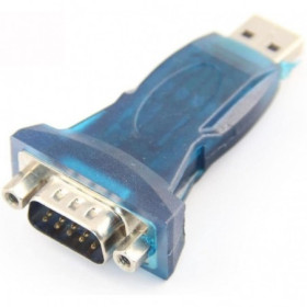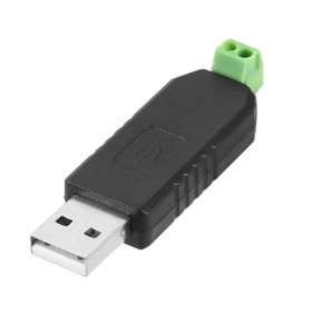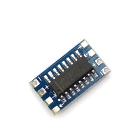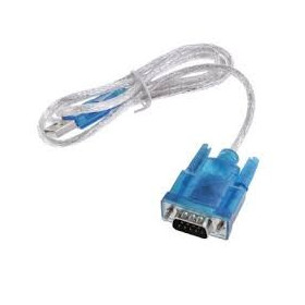

Product images are for informational purposes only and may vary slightly depending on the batch and supplier. Product specifications and prices may be subject to change without notice. We do our best to provide accurate and complete product specifications, but they may not be completely accurate. If you encounter any such situation, please let us know.
The product is intended for specialists and requires qualified and authorized personnel. The product does not include assembly/use instructions . Putting the product into operation by unqualified persons leads to the loss of the warranty according to the Terms and Conditions on the site.
The specified technical parameters (current, power, etc.) represent maximum allowable values under ideal operating conditions. For safe use and optimal lifespan, it is recommended to operate the product continuously at no more than 50% of the specified maximum values.
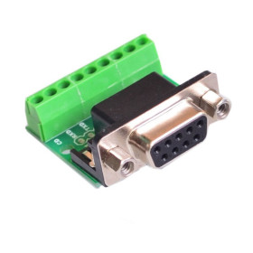
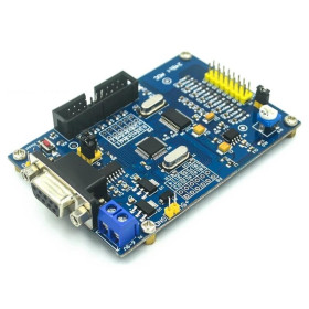
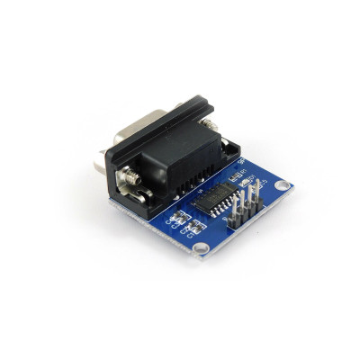
MAX3232 RS232 to TTL Converter Module, DB9 Female Connector, 3.3-5V Power Supply, 4-Pin TTL
The MAX3232 RS232 to TTL converter enables quick connection between equipment with an RS232 serial port and boards with TTL logic level, ideal for Arduino, ESP and industrial modules. It provides stable bidirectional TX RX communication, operates with external 3.3-5V power, has levels compatible with both 3.3V and 5V, and is compact and easy to integrate into projects and test benches.
Shipping by Wednesday 11 November
Buying this product earns you 0.25 RON in loyalty points.

International fast shipping within EU. Free Shipping for orders above 100 EUR in most EU countries.

We ship from our stock within 24H

You earn points with every order, worth 5%.
The RS232 to TTL converter module with the MAX3232 chip links a classic RS232 serial port, with DB9 connector, to a microcontroller that works at logic levels of 3.3 V or 5 V. It transmits and receives data in both directions over three wires (TX, RX and ground), without flow control lines, and is suitable for connecting older or industrial equipment, such as laboratory instruments, readers, router consoles, GSM modules or PLCs, or for communication with a computer COM port.
The MAX3232 integrated circuit (U1 on the board) has two drivers and two receivers, and the module uses a single channel. A charge pump formed by the 100 nF capacitors C1 - C4 generates from the 3.3 - 5 V supply the positive and negative voltages required by the RS232 line, where a logic 1 is a voltage between -3 V and -15 V, and a logic 0 is a voltage between +3 V and +15 V. The circuit operates at speeds of up to 250 kbit/s, and the logic level of the TTL side is equal to the supply voltage.
The main features include the DB9 female connector for the RS232 side, the 4-pin header with 2.54 mm pitch for the TTL side (GND, TXD, RXD, VCC), the red power LED D1 with the 1 kohm resistor R1, the 100 nF capacitor C5 for supply filtering and two mounting holes. The module is powered externally, at 3.3 - 5 VDC, through the VCC and GND pins.
Through the TTL UART interface, the module connects directly to Arduino, ESP32, STM32, Raspberry Pi and other boards that have a serial port, and through the DB9 connector it links to computers, PLCs and equipment with a classic serial port.
Specifications:
Supply voltage: 3.3 - 5 VDC (external supply)
Operating current: 6 mA
Integrated circuit: MAX3232
Channels used: 1 (TX / RX)
Maximum transmission speed: 250 kbit/s
RS232 connector: DB9 female
RS232 signals: TX, RX, GND (no flow control)
TTL interface: 4 pins (GND, TXD, RXD, VCC), 2.54 mm pitch
TTL logic level: 3.3 V or 5 V, equal to the supply voltage
Indicator: red power LED D1
Dimensions: 33 x 32 mm
Layout:
| Element | Function |
|---|---|
| DB9 female connector | The RS232 side of the module. It is inserted into a DB9 male connector, for example of a USB to RS232 cable or of a computer COM port. |
| U1 MAX3232 | Integrated circuit that converts RS232 levels to TTL levels and vice versa. One transmission channel and one reception channel are used. |
| 4-pin TTL header | The logic level side, towards the microcontroller. The pins are GND, TXD, RXD and VCC. |
| LED D1 (red) | Indicates the presence of power. It lights up when the VCC and GND pins are powered and stays off without power. |
| Resistor R1 | 1 kohm resistor that limits the current through LED D1. |
| Capacitors C1 - C4 | 100 nF capacitors of the MAX3232 charge pump, which produce the positive and negative voltages of the RS232 line. |
| Capacitor C5 | 100 nF capacitor for supply filtering. |
| Mounting holes | Board fixing. |
The module has no buttons, potentiometers, jumpers or switches, so there is nothing to adjust.
Pinout:
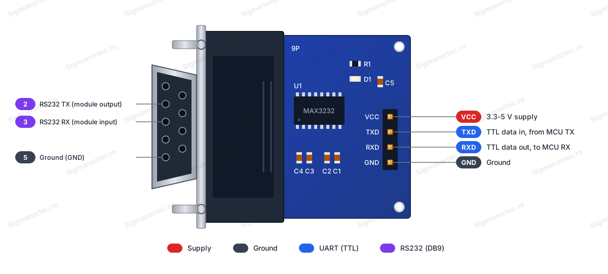
| Connector | Pin | Function |
|---|---|---|
| TTL header | VCC | Power supply 3.3 - 5 VDC |
| TTL header | GND | Ground |
| TTL header | RXD | Data output of the module, towards the RX pin of the microcontroller |
| TTL header | TXD | Data input of the module, from the TX pin of the microcontroller |
| DB9 female | 2 | RS232 transmission (output of the module) |
| DB9 female | 3 | RS232 reception (input of the module) |
| DB9 female | 5 | Ground (GND) |
Usage:
Connect the GND pin of the module to the microcontroller ground and the VCC pin to 3.3 V or 5 V, at the same level as the logic of the board used.
Do not exceed 5 V on the VCC pin and respect the supply polarity.
Connect the RXD pin of the module to the RX pin of the microcontroller and the TXD pin of the module to the TX pin of the microcontroller, directly, without crossing. If no data appears on the first test, swap the two wires.
Never connect the DB9 connector pins directly to the microcontroller pins, because RS232 levels are between ±3 V and ±15 V and can destroy the pins.
Insert the DB9 female connector into a DB9 male connector, for example of a USB to RS232 cable or of a computer COM port. If the external device also has a female connector, use a null-modem cable.
Power the module, and the LED D1 will light up immediately. If it stays off, check the VCC and GND connections.
Set the same speed and format on both sides of the link, for example 9600 baud, 8N1.
The module has no buttons, jumpers or switches, and LED D1 is the only indicator.
For stable results, use short cables, a common ground between all equipment and the same transmission speed on both sides.
- Supply voltage
- 3.3-5 V DC
- Dimensions
- 33 x 32 mm
- Interface
- RS232, TTL
- Logic voltage
- 3.3 V sau 5 V
- Connector type
- DB9 female
- Current
- 6 mA
- Number of channels
- 1
- Integrated circuit
- MAX3232
- Pin pitch
- 2.54 mm
- Baud rate
- 250 kbit/s
Produs destinat utilizarii in proiecte electronice, automatizari, prototipare, educatie si cercetare.
Produsul trebuie utilizat numai conform specificatiilor tehnice mentionate in descriere si/sau in documentatia produsului.
Avertismente generale de siguranta:
Nu utilizati produsul la tensiuni, curenti sau temperaturi peste valorile specificate.
Montajul si conectarea trebuie realizate de persoane cu cunostinte tehnice minime in domeniul electric/electronic.
Evitati scurtcircuitele, inversarea polaritatii si conectarea gresita a alimentarii.
Nu lasati produsul alimentat nesupravegheat in timpul testelor.
Produsul nu este jucarie si nu este destinat copiilor.
Pentru modulele electronice, se recomanda utilizarea in carcase, panouri sau montaje protejate, dupa caz.
Identificare produs:
Denumirea produsului, codul/SKU-ul si caracteristicile tehnice sunt mentionate in pagina produsului si/sau pe eticheta ambalajului.
Producator / Importator / Distribuitor:
Sigmanortec S.R.L.
Calea Bucuresti nr. 9, Targu Jiu, Gorj, Romania
E-mail: [email protected]
Website: www.sigmanortec.ro
Persoana responsabila in UE:
Sigmanortec S.R.L.
Calea Bucuresti nr. 9, Targu Jiu, Gorj, Romania
E-mail: [email protected]
Documentatie si siguranta:
Pentru informatii suplimentare, fise tehnice, declaratii de conformitate sau instructiuni, ne puteti contacta la [email protected].
Reviews (1) - Review moderation

Promptitudine in procesare comenzii / livrare. informatie la indemana / la timp
/*
  RS232 to TTL converter module (MAX3232) - two-way serial test

  Board (Arduino IDE, Tools > Board): Arduino Uno
  Board package: Arduino AVR Boards (comes with the Arduino IDE)
  Libraries: none to install. SoftwareSerial is included with the Arduino IDE.

  Wiring:
    Module VCC -> Arduino 5V
    Module GND -> Arduino GND
    Module RXD -> Arduino D10 (SoftwareSerial RX)
    Module TXD -> Arduino D11 (SoftwareSerial TX)
    Module DB9 female -> USB to RS232 cable with DB9 male, connected to the PC

  Settings: 9600 baud, 8N1 on the Serial Monitor and on the terminal
  of the USB to RS232 cable (for example PuTTY).
*/

#include <SoftwareSerial.h>

const uint8_t RX_PIN = 10;                  // Arduino receives here (module RXD)
const uint8_t TX_PIN = 11;                  // Arduino transmits here (module TXD)
const unsigned long BAUD_RATE = 9600;       // Same speed on all sides
const unsigned long SEND_INTERVAL = 2000;   // Time between test messages in ms
const uint8_t BUFFER_SIZE = 64;             // Maximum length of a received line

SoftwareSerial rs232(RX_PIN, TX_PIN);       // Software serial port for the module

char rxBuffer[BUFFER_SIZE];                 // Buffer for the line received from RS232
uint8_t rxIndex = 0;                        // Current position in the buffer
unsigned long lastSendTime = 0;             // Time of the last test message
unsigned int counter = 0;                   // Number of test messages sent

void setup() {
  Serial.begin(BAUD_RATE);                  // USB serial port for the Serial Monitor
  rs232.begin(BAUD_RATE);                   // Serial port to the RS232 module

  Serial.println(F("RS232 to TTL test started at 9600 baud."));
  Serial.println(F("Open a terminal on the COM port of the USB-RS232 cable (9600, 8N1)."));
}

void loop() {
  // Read what arrives from the RS232 side and print it as a line
  while (rs232.available() > 0) {
    char c = rs232.read();
    if (c == '\n' || c == '\r') {
      if (rxIndex > 0) {                    // Ignore empty lines
        rxBuffer[rxIndex] = '\0';           // End the string
        Serial.print(F("Received from RS232: "));
        Serial.println(rxBuffer);
        rxIndex = 0;                        // Start a new line
      }
    } else if (rxIndex < BUFFER_SIZE - 1) {
      rxBuffer[rxIndex++] = c;              // Store the character
    }
  }

  // Forward what you type in the Serial Monitor to the RS232 side
  while (Serial.available() > 0) {
    rs232.write(Serial.read());
  }

  // Send a numbered test message at a fixed interval
  if (millis() - lastSendTime >= SEND_INTERVAL) {
    lastSendTime = millis();
    counter++;
    rs232.print(F("Hello from Arduino #"));
    rs232.print(counter);
    rs232.print(F("\r\n"));                 // Line end for the terminal
    Serial.print(F("Sent to RS232: Hello from Arduino #"));
    Serial.println(counter);
  }
}
The RS232 to TTL module with MAX3232 connects a classic RS232 serial port, with a DB9 connector, to a microcontroller that works at logic levels of 3.3 V or 5 V. Use it when you want to connect older or industrial devices, such as laboratory equipment, readers, router consoles, GSM modules or PLCs, or when you want to communicate with a COM port on a computer.
In this tutorial we use an Arduino Uno R3 board, because the module only converts signal levels and needs a microcontroller to send and receive the data. The test consists of a serial link in both directions between the Arduino and a computer, through a USB to RS232 cable.

How it works:
A microcontroller produces TTL levels, that is 0 V for logic 0 and 3.3 V or 5 V for logic 1. The RS232 standard uses different levels and inverted logic: a logic 1 is a negative voltage, between -3 V and -15 V, and a logic 0 is a positive voltage, between +3 V and +15 V. If you connected an RS232 port directly to an Arduino pin, you would exceed the voltage that the pin can tolerate and could damage it.
The MAX3232 integrated circuit (U1 on the board) solves the problem. It has two drivers and two receivers, and the module uses a single channel. A charge pump made of the 100 nF capacitors C1 - C4 generates the positive and negative voltages needed by the RS232 line from the 3.3 - 5 V supply. Capacitor C5 filters the supply. The integrated circuit works between 3.0 V and 5.5 V and reaches 250 kbit/s.
On the female DB9 connector, pin 2 is the transmit output of the module, pin 3 is the receive input and pin 5 is ground. There are no flow control lines. On the TTL side, the RXD pin is the output of the module towards the receive pin of the microcontroller, and the TXD pin is the input of the module from the transmit pin of the microcontroller. For this reason the connection is made directly, RXD to RX and TXD to TX, without crossing.
At 9600 baud with the 8N1 format, each character occupies 10 bits, that is one start bit, eight data bits and one stop bit. The duration of one bit is 1 / 9600, that is about 104 microseconds, and one character lasts about 1.04 ms. This gives roughly 960 characters per second.
Connection:
Power the module from the 5V pin of the Arduino Uno board, which gives it logic levels of 5 V, suitable for the Uno. If you use a 3.3 V board, power the module from 3.3 V as well. The Arduino board remains powered through USB from the computer. Never connect the pins of the DB9 connector directly to the Arduino pins. Only the four pins of the TTL header, marked GND, TXD, RXD and VCC, connect to the Arduino.
The DB9 connector of the module is female and plugs directly into a male DB9 connector, such as the one of a USB to RS232 cable or of a COM port on a computer. If the device you connect also has a female connector, use a null-modem cable.
| Product pin | Connect to | Role |
|---|---|---|
| VCC | Arduino Uno 5V | Power supply 3.3 - 5 V |
| GND | Arduino Uno GND | Common ground |
| RXD | Arduino Uno D10 | Data from the module to the Arduino (RX pin of SoftwareSerial) |
| TXD | Arduino Uno D11 | Data from the Arduino to the module (TX pin of SoftwareSerial) |
| Female DB9 connector | USB to RS232 cable with male DB9, connected to the computer | RS232 line with pin 2 transmit, pin 3 receive, pin 5 ground |
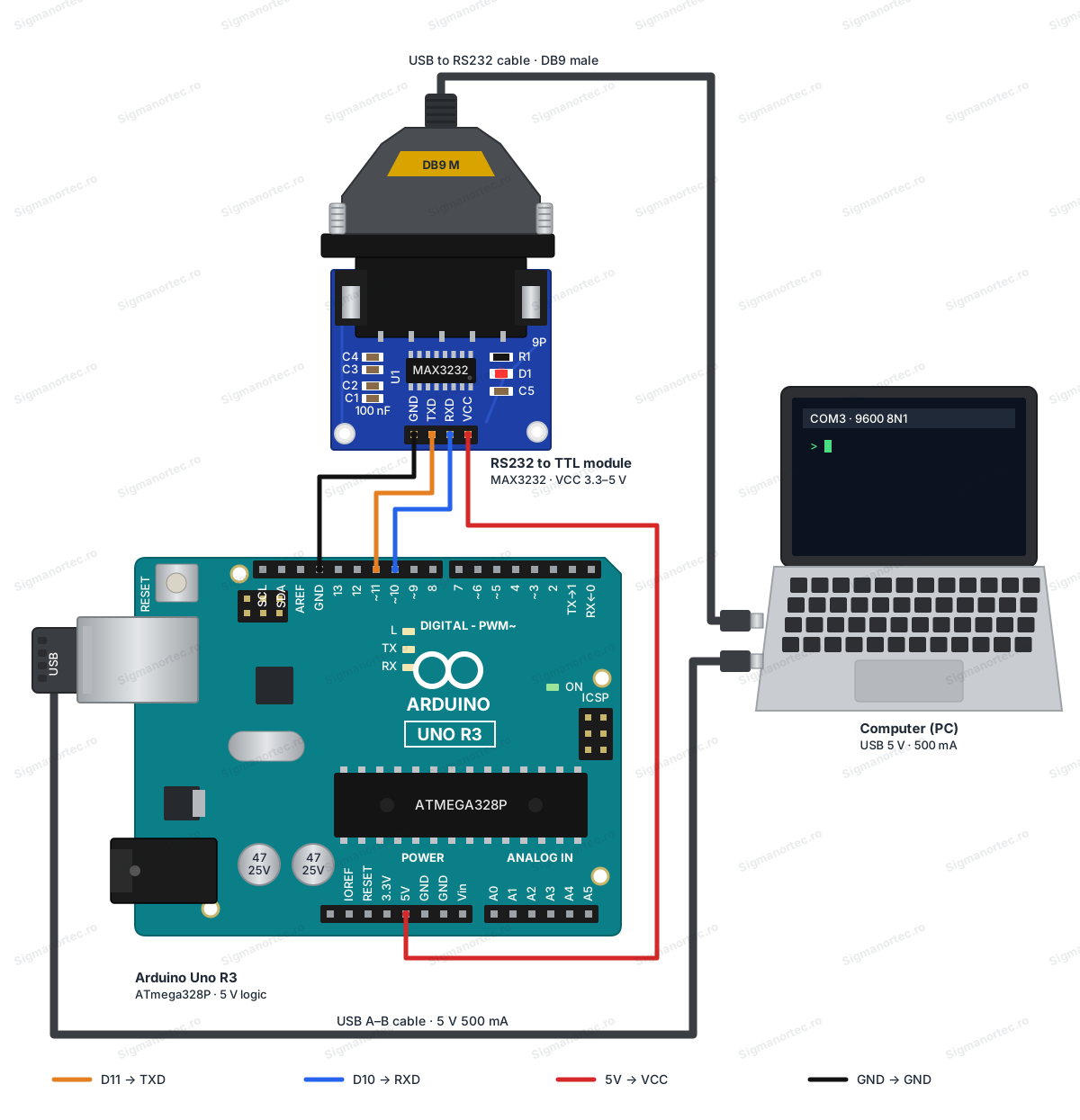
We chose pins D10 and D11 with the SoftwareSerial library because pins D0 and D1 of the Uno board are used by the hardware serial port, which communicates with the Serial Monitor through USB. This way you can see the messages on the computer without disconnecting anything.
Buttons, settings and indicators:
The module has no buttons, potentiometers, jumpers or switches, so there is nothing to adjust. It has a single indicator and two connectors.
| Element | What it does | How to use it |
|---|---|---|
| LED D1 (red, with the 1 kohm resistor R1) | Indicates that the module is powered | It lights up when VCC and GND are powered. If it stays off, check the power connections. |
| TTL header (GND, TXD, RXD, VCC) | The logic level side, towards the microcontroller | Connect it to the Arduino according to the connection table. |
| Female DB9 connector | The RS232 side, towards the external device | Plug it into a male DB9 connector, for example that of a USB to RS232 cable. |
After you make the connections and connect the Arduino to USB, the LED D1 should light up immediately. This is the only visible sign that the module is powered. To see that the data transfer works as well, use the program below.
Board and libraries:
In the Arduino IDE, select the Arduino Uno board from Tools > Board, from the Arduino AVR Boards package, which comes with the Arduino IDE and can be found in the Boards Manager. No library needs to be installed, because SoftwareSerial is part of the Arduino IDE.
On the computer you also need a terminal program for the COM port of the USB to RS232 cable, for example PuTTY on Windows or screen on Linux and macOS.
The code:
The program sends a numbered message to the RS232 port every two seconds and displays on the Serial Monitor everything it receives from there. At the same time, what you type in the Serial Monitor is sent further on the RS232 line.
/*
  RS232 to TTL converter module (MAX3232) - two-way serial test
  Board (Arduino IDE, Tools > Board): Arduino Uno
  Board package: Arduino AVR Boards (comes with the Arduino IDE)
  Libraries: none to install. SoftwareSerial is included with the Arduino IDE.
  Wiring:
    Module VCC -> Arduino 5V
    Module GND -> Arduino GND
    Module RXD -> Arduino D10 (SoftwareSerial RX)
    Module TXD -> Arduino D11 (SoftwareSerial TX)
    Module DB9 female -> USB to RS232 cable with DB9 male, connected to the PC
  Settings: 9600 baud, 8N1 on the Serial Monitor and on the terminal
  of the USB to RS232 cable (for example PuTTY).
*/
#include <SoftwareSerial.h>
const uint8_t RX_PIN = 10;                  // Arduino receives here (module RXD)
const uint8_t TX_PIN = 11;                  // Arduino transmits here (module TXD)
const unsigned long BAUD_RATE = 9600;       // Same speed on all sides
const unsigned long SEND_INTERVAL = 2000;   // Time between test messages in ms
const uint8_t BUFFER_SIZE = 64;             // Maximum length of a received line
SoftwareSerial rs232(RX_PIN, TX_PIN);       // Software serial port for the module
char rxBuffer[BUFFER_SIZE];                 // Buffer for the line received from RS232
uint8_t rxIndex = 0;                        // Current position in the buffer
unsigned long lastSendTime = 0;             // Time of the last test message
unsigned int counter = 0;                   // Number of test messages sent
void setup() {
  Serial.begin(BAUD_RATE);                  // USB serial port for the Serial Monitor
  rs232.begin(BAUD_RATE);                   // Serial port to the RS232 module
  Serial.println(F("RS232 to TTL test started at 9600 baud."));
  Serial.println(F("Open a terminal on the COM port of the USB-RS232 cable (9600, 8N1)."));
}
void loop() {
  // Read what arrives from the RS232 side and print it as a line
  while (rs232.available() > 0) {
    char c = rs232.read();
    if (c == '\n' || c == '\r') {
      if (rxIndex > 0) {                    // Ignore empty lines
        rxBuffer[rxIndex] = '\0';           // End the string
        Serial.print(F("Received from RS232: "));
        Serial.println(rxBuffer);
        rxIndex = 0;                        // Start a new line
      }
    } else if (rxIndex < BUFFER_SIZE - 1) {
      rxBuffer[rxIndex++] = c;              // Store the character
    }
  }
  // Forward what you type in the Serial Monitor to the RS232 side
  while (Serial.available() > 0) {
    rs232.write(Serial.read());
  }
  // Send a numbered test message at a fixed interval
  if (millis() - lastSendTime >= SEND_INTERVAL) {
    lastSendTime = millis();
    counter++;
    rs232.print(F("Hello from Arduino #"));
    rs232.print(counter);
    rs232.print(F("\r\n"));                 // Line end for the terminal
    Serial.print(F("Sent to RS232: Hello from Arduino #"));
    Serial.println(counter);
  }
}
How the code works:
At the beginning, the constants RX_PIN (10) and TX_PIN (11), the speed BAUD_RATE (9600), the interval SEND_INTERVAL (2000 ms) and the size BUFFER_SIZE (64) of the received line are defined. The object rs232 is the software serial port created with SoftwareSerial on pins D10 and D11. The variables rxBuffer, rxIndex, lastSendTime and counter store the line being received, the position in it, the moment of the last sent message and the number of messages sent.
In the setup() function we start the hardware serial port Serial for the Serial Monitor and the rs232 port towards the module, both at 9600 baud, then we display two start-up messages.
In the loop() function we do three things. First we read the characters arriving from the module with rs232.read() and add them to rxBuffer. When an end of line ('\n' or '\r') appears and the buffer is not empty, we terminate the string with '\0' and display it with the prefix Received from RS232. Empty lines are ignored, and the buffer cannot be exceeded.
Then we retransmit on the RS232 line everything you type in the Serial Monitor, character by character, with rs232.write(Serial.read()). At the end, with millis(), we check whether 2000 ms have passed since the last message. If so, we increment counter, send the text Hello from Arduino # followed by the number and the end of line \r\n, and display the same message in the Serial Monitor as well.
Result:
Open the Serial Monitor at 9600 baud and a terminal (PuTTY or screen) on the COM port of the USB to RS232 cable, also at 9600 baud, 8N1. In the Serial Monitor the messages sent every two seconds appear, and in the terminal the text Hello from Arduino appears with the message number. What you type in the terminal and send with Enter appears in the Serial Monitor, with the prefix Received from RS232.
RS232 to TTL test started at 9600 baud.
Open a terminal on the COM port of the USB-RS232 cable (9600, 8N1).
Sent to RS232: Hello from Arduino #1
Sent to RS232: Hello from Arduino #2
Received from RS232: Test from PC
Sent to RS232: Hello from Arduino #3
Sent to RS232: Hello from Arduino #4
Received from RS232: Second message
Sent to RS232: Hello from Arduino #5
Common problems:
The LED D1 does not light up. The cause is the lack of power to the module. Check the connections VCC to 5V and GND to GND, as well as the orientation of the connection on the TTL header, where the markings are GND, TXD, RXD, VCC.
Nothing is received in the Serial Monitor or in the terminal. The cause may be the cable or the data wires. Check that the terminal uses the correct COM port, at 9600 baud, 8N1. If the external device has a female DB9 connector, use a null-modem cable. If the connections are correct and still no data appears, swap the wires on pins D10 and D11, because the RXD and TXD markings may differ from one board version to another.
Strange characters appear in the terminal. The cause is a different speed on the two sides or a missing common ground. Set the same speed and the same format everywhere and check the GND connection.
Data is lost or corrupted at high speeds. The cause is the SoftwareSerial library, which is not reliable at high speeds on the Arduino Uno. Use 9600 baud or at most 19200 baud, or a hardware serial port.
The 3.3 V board behaves unstably or gets hot. The cause is powering the module from 5 V, which gives it logic levels of 5 V. Power the module from 3.3 V.
Limitations and tips:
The module only converts the TX, RX and ground signals. There are no flow control lines (RTS, CTS), so it is not suitable for equipment that requires them. The maximum speed of the MAX3232 circuit is 250 kbit/s, and the TTL side accepts a supply between 3.3 V and 5 V.
For long connections, use shielded cables and keep a common ground. With this module you can build a data logger for a device with a serial port, a bridge between an industrial device and a microcontroller board, or a serial console for a router.