
Product images are for informational purposes only and may vary slightly depending on the batch and supplier. Product specifications and prices may be subject to change without notice. We do our best to provide accurate and complete product specifications, but they may not be completely accurate. If you encounter any such situation, please let us know.
The product is intended for specialists and requires qualified and authorized personnel. The product does not include assembly/use instructions . Putting the product into operation by unqualified persons leads to the loss of the warranty according to the Terms and Conditions on the site.
The specified technical parameters (current, power, etc.) represent maximum allowable values under ideal operating conditions. For safe use and optimal lifespan, it is recommended to operate the product continuously at no more than 50% of the specified maximum values.
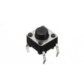
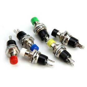
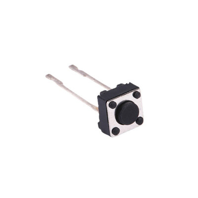
PCB Mini Button, 6x6x5 mm, 2 pins, normally open, 12V 50mA
Ideal for prototyping and quick commands in electronic projects, this mini tactile button mounts easily on a PCB and can be used directly on a breadboard. It has a compact 6x6x5 mm format, 2 pins for simple connection, precise actuation with tactile feedback and a robust construction for repeated use in test setups or final products.
Shipping by Wednesday 11 November
Buying this product earns you 0.02 RON in loyalty points.

International fast shipping within EU. Free Shipping for orders above 100 EUR in most EU countries.

We ship from our stock within 24H

You earn points with every order, worth 5%.
The mini tactile button is a normally open SPST switch with two pins for through-hole mounting on a PCB or breadboard. It closes an electrical contact while the cap is pressed and reopens it when released, making it suitable for manual commands such as power on, reset, mode selection or confirming a setting.
The body measures 6 x 6 x 5 mm, has a round actuator cap and two connection pins with no polarity. The contact is open at rest and closes when pressed, and an internal spring returns the cap to its rest position when released. The maximum contact rating is 12 VDC and 50 mA, which makes it suitable for low-level command signals.
Key features include the round actuator cap, the plastic body with metal cover, the two pins for through-hole mounting and the small dimensions, which allow mounting on boards with limited space. The button needs no power supply, as it is a passive contact.
Specifications:
Maximum contact voltage: 12 VDC
Maximum contact current: 50 mA
Contact type: SPST, normally open
Number of pins: 2
Mounting: Through-hole (THT), breadboard compatible
Dimensions: 6 x 6 x 5 mm
Layout:
| Element | Function |
|---|---|
| Round actuator cap | The button itself. When pressed it closes the contact between the two pins, for as long as it is held down, and when released the contact opens again. A short press and a long press have the same electrical effect, the contact remaining closed as long as the cap is pressed. |
| Plastic body with metal cover | Protects the internal mechanism and holds the position of the pins. |
| Connection pins (2) | The contact ends. They have no polarity, so they can be connected in any order to the signal and to ground or to the load. |
Usage:
Insert the button into the holes of the PCB or breadboard so that the two pins are in different rows, then solder the pins if the assembly is permanent.
Connect one of the pins to the commanded signal or load and the other pin to ground or to the command voltage. The pins have no polarity, so the order does not matter.
Do not exceed 12 VDC and 50 mA through the contacts, and do not use the button to directly switch large loads or mains voltage.
When the button drives a logic input, use a pull-up or pull-down resistor, so that the input does not float while the contact is open.
Press the cap to close the contact and release it to open the contact. The starting position is the button released, with the contact open.
To check the button, measure with a multimeter in continuity mode between the two pins. The contact must be open at rest and show continuity only while the cap is pressed.
When closing, the contacts bounce for a few milliseconds. For reliable readings, filter these bounces in the program or with a small capacitor in parallel with the button.
When soldering, keep the soldering iron contact time short and do not press the cap during soldering, so as not to deform the mechanism.
- Dimensions
- 6 x 6 x 5 mm
- Number of pins
- 2
- Maximum current
- 50 mA
- Mounting
- Through-hole (THT)
- Maximum voltage
- 12 V DC
- Contact type
- SPST, normally open
Produs destinat utilizarii in proiecte electronice, automatizari, prototipare, educatie si cercetare.
Produsul trebuie utilizat numai conform specificatiilor tehnice mentionate in descriere si/sau in documentatia produsului.
Avertismente generale de siguranta:
Nu utilizati produsul la tensiuni, curenti sau temperaturi peste valorile specificate.
Montajul si conectarea trebuie realizate de persoane cu cunostinte tehnice minime in domeniul electric/electronic.
Evitati scurtcircuitele, inversarea polaritatii si conectarea gresita a alimentarii.
Nu lasati produsul alimentat nesupravegheat in timpul testelor.
Produsul nu este jucarie si nu este destinat copiilor.
Pentru modulele electronice, se recomanda utilizarea in carcase, panouri sau montaje protejate, dupa caz.
Identificare produs:
Denumirea produsului, codul/SKU-ul si caracteristicile tehnice sunt mentionate in pagina produsului si/sau pe eticheta ambalajului.
Producator / Importator / Distribuitor:
Sigmanortec S.R.L.
Calea Bucuresti nr. 9, Targu Jiu, Gorj, Romania
E-mail: [email protected]
Website: www.sigmanortec.ro
Persoana responsabila in UE:
Sigmanortec S.R.L.
Calea Bucuresti nr. 9, Targu Jiu, Gorj, Romania
E-mail: [email protected]
Documentatie si siguranta:
Pentru informatii suplimentare, fise tehnice, declaratii de conformitate sau instructiuni, ne puteti contacta la [email protected].
Reviews (6) - Review moderation

Nu am ce reprosa, buton, merge ok :)
Produse de buna calitate. Recomand totusi masurarea inainte de montaj.(am gasit 8a) Nu este in sine o nemultumire ci doar o observatie.
Ok
Bun
Produsul este de calitate 10/10
/*
  Board: Arduino Uno (Tools > Board > Arduino AVR Boards > Arduino Uno)
  Libraries: none needed, only the core Arduino functions are used

  Wiring:
    Button pin 1 -> GND (the GND pin next to AREF)
    Button pin 2 -> D2
  The internal pull-up resistor is used, so no external resistor is needed.
*/

const uint8_t BUTTON_PIN = 2;               // Digital pin connected to the button
const uint8_t LED_PIN = 13;                 // Built-in LED "L" on the Arduino Uno
const unsigned long DEBOUNCE_MS = 30;       // Time a new state must stay stable

int lastReading = HIGH;                     // Last raw reading of the button pin
int stableState = HIGH;                     // Last confirmed (debounced) state
unsigned long lastChangeTime = 0;           // Moment of the last raw change
unsigned long pressCount = 0;               // Number of confirmed presses

void setup() {
  Serial.begin(9600);                       // Start the serial monitor at 9600 baud
  pinMode(BUTTON_PIN, INPUT_PULLUP);        // Enable the internal pull-up: released = HIGH, pressed = LOW
  pinMode(LED_PIN, OUTPUT);                 // LED pin as output
  digitalWrite(LED_PIN, LOW);               // Start with the LED off

  Serial.println("Button test started");
  Serial.println("Button on pin D2, internal pull-up enabled");
  Serial.println("Button released (idle)");
}

void loop() {
  int reading = digitalRead(BUTTON_PIN);    // Read the raw state of the button

  // If the raw reading changed, restart the debounce timer
  if (reading != lastReading) {
    lastChangeTime = millis();
    lastReading = reading;
  }

  // Accept the new state only if it stayed unchanged longer than DEBOUNCE_MS
  if ((millis() - lastChangeTime) > DEBOUNCE_MS && reading != stableState) {
    stableState = reading;

    if (stableState == LOW) {
      // LOW means the contacts are closed: the button is pressed
      digitalWrite(LED_PIN, HIGH);          // Turn the LED on
      pressCount++;                         // Count the press
      Serial.print("Button PRESSED - LED on - press count: ");
      Serial.println(pressCount);
    } else {
      // HIGH means the contacts are open: the button is released
      digitalWrite(LED_PIN, LOW);           // Turn the LED off
      Serial.println("Button released - LED off");
    }
  }
}
This tutorial uses the Arduino Uno R3 board, because a 2-pin button cannot work on its own. It closes or opens a contact, and a microcontroller must read the state of this contact. The PCB Mini 6x6x5 mm tactile button is a normally open SPST switch, with two pins for through-hole or breadboard mounting. You will use it in projects for power on, reset, selecting a mode, confirming a setting or manually triggering a function.

How it works:
At rest, the two pins of the button are not connected to each other. When you press the cap, an internal metal contact connects them electrically and, as long as you keep it pressed, current can flow from one pin to the other. On release, a spring returns the contact to the open position. The pins have no polarity, so any pin can go to either of the two connections.
An open contact left unconnected does not give a safe logic value, and the Arduino pin would read noise. That is why we use the internal pull-up resistor of the ATmega328P microcontroller, enabled with pinMode(2, INPUT_PULLUP). This resistor, approximately 20 - 50 kohm, pulls pin D2 towards 5 V. With the button released, the pin reads HIGH. When you press, the button connects D2 to GND and the pin reads LOW. The logic is therefore inverted: pressed means LOW.
The current through the button is very small. With 5 V and an internal resistance of 20 kohm, at most 5 V / 20 kohm = 0.25 mA flows, far below the 50 mA at 12 V DC limit of tactile buttons of this type.
Metal contacts do not close cleanly, but vibrate for a few milliseconds (the bounce effect). Without protection, a single press can be read as several presses. The program in this tutorial ignores changes shorter than 30 ms, an interval sufficient for small tactile buttons.
Wiring:
Power the Arduino Uno R3 through the USB A-B cable from the computer, at 5 V. You do not need an external resistor, level converter or any other power source. Do not connect the button to 5 V or 3.3 V, only to pin D2 and GND. If you use a breadboard, position the button so that its two pins are in different rows.
| Product pin | Connects to | Role |
|---|---|---|
| Pin 1 | GND (pin next to AREF) | Ground, the end that pulls pin D2 to LOW when pressed |
| Pin 2 | D2 (digital pin 2) | Signal read by the Arduino with the internal pull-up enabled |
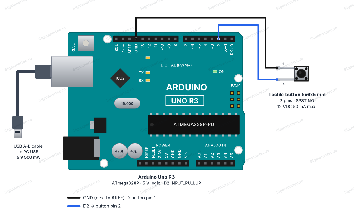
The numbers 1 and 2 are only labels in the diagram, the pins on the button are not marked and can be used in any order.
Buttons, adjustments and indicators:
| Element | What it does | How to use it |
|---|---|---|
| 6x6x5 mm button (round cap) | Connects the two pins together as long as it is pressed | Press and hold to pull D2 to LOW, release to return to HIGH |
| L LED on the Arduino Uno board (pin 13) | Shows the button state in the test program | Lights up while the button is pressed and turns off on release |
The button has no potentiometers, jumpers or adjustment switches. The starting position is the button released, with LED L off and pin D2 at HIGH.
To check operation, press the button. The L LED on the board should light up immediately, and the serial monitor should display a press message. On release, the LED turns off and a release message appears.
Short and long presses have no different meanings in this program, the button only reports its state in real time.
Board and libraries:
In the Arduino IDE select from Tools > Board the Arduino Uno board, from the Arduino AVR Boards package. This package comes installed with the Arduino IDE, and if it is missing install it from Boards Manager. Under Tools > Port choose the COM port of the board.
The program uses only the basic Arduino functions, so no library needs to be installed.
The code:
The program monitors the button on pin D2, filters contact bounce, lights the L LED while the button is pressed and counts the presses.
/*
  Board: Arduino Uno (Tools > Board > Arduino AVR Boards > Arduino Uno)
  Libraries: none needed, only the core Arduino functions are used
  Wiring:
    Button pin 1 -> GND (the GND pin next to AREF)
    Button pin 2 -> D2
  The internal pull-up resistor is used, so no external resistor is needed.
*/
const uint8_t BUTTON_PIN = 2;               // Digital pin connected to the button
const uint8_t LED_PIN = 13;                 // Built-in LED "L" on the Arduino Uno
const unsigned long DEBOUNCE_MS = 30;       // Time a new state must stay stable
int lastReading = HIGH;                     // Last raw reading of the button pin
int stableState = HIGH;                     // Last confirmed (debounced) state
unsigned long lastChangeTime = 0;           // Moment of the last raw change
unsigned long pressCount = 0;               // Number of confirmed presses
void setup() {
  Serial.begin(9600);                       // Start the serial monitor at 9600 baud
  pinMode(BUTTON_PIN, INPUT_PULLUP);        // Enable the internal pull-up: released = HIGH, pressed = LOW
  pinMode(LED_PIN, OUTPUT);                 // LED pin as output
  digitalWrite(LED_PIN, LOW);               // Start with the LED off
  Serial.println("Button test started");
  Serial.println("Button on pin D2, internal pull-up enabled");
  Serial.println("Button released (idle)");
}
void loop() {
  int reading = digitalRead(BUTTON_PIN);    // Read the raw state of the button
  // If the raw reading changed, restart the debounce timer
  if (reading != lastReading) {
    lastChangeTime = millis();
    lastReading = reading;
  }
  // Accept the new state only if it stayed unchanged longer than DEBOUNCE_MS
  if ((millis() - lastChangeTime) > DEBOUNCE_MS && reading != stableState) {
    stableState = reading;
    if (stableState == LOW) {
      // LOW means the contacts are closed: the button is pressed
      digitalWrite(LED_PIN, HIGH);          // Turn the LED on
      pressCount++;                         // Count the press
      Serial.print("Button PRESSED - LED on - press count: ");
      Serial.println(pressCount);
    } else {
      // HIGH means the contacts are open: the button is released
      digitalWrite(LED_PIN, LOW);           // Turn the LED off
      Serial.println("Button released - LED off");
    }
  }
}
How the code works:
At the beginning we define the constants. BUTTON_PIN is pin 2, where the button is connected, LED_PIN is pin 13 of the L LED on the board, and DEBOUNCE_MS is the 30 ms time during which a change must remain stable to be accepted.
The variables lastReading and stableState store the last raw reading and the last confirmed state, both starting from HIGH, meaning button released. The variable lastChangeTime stores the moment of the last raw change, and pressCount counts the confirmed presses.
In setup() we start the serial monitor at 9600 baud, enable the internal pull-up with pinMode(BUTTON_PIN, INPUT_PULLUP), set LED_PIN as output and turn it off, then print the start messages.
In loop() we read the pin with digitalRead(). If the raw reading differs from lastReading, we restart the timer with millis(). When the state remains unchanged for more than DEBOUNCE_MS and differs from stableState, we consider it confirmed. If it is LOW, we turn on the LED, increase pressCount and print the press number. If it is HIGH, we turn off the LED and print the release message.
Result:
Open the serial monitor in the Arduino IDE at 9600 baud. At startup the start messages appear, then one message for each press and release of the button.
Button test started
Button on pin D2, internal pull-up enabled
Button released (idle)
Button PRESSED - LED on - press count: 1
Button released - LED off
Button PRESSED - LED on - press count: 2
Button released - LED off
Button PRESSED - LED on - press count: 3
Button released - LED off
Common problems:
Nothing appears on the serial monitor. The cause is usually the wrong port or speed. Select the correct port from Tools > Port and set the serial monitor to 9600 baud.
The button seems pressed all the time or does not react. The cause may be a pin connected to a pin other than D2 or GND, or a button mounted on a breadboard with both pins in the same row, in which case the contact is short-circuited. Move one pin to another row and check the connections.
A single press is counted several times. The cause is contact bounce. Keep the filtering in the program and, if the button is very worn, increase DEBOUNCE_MS to 50 ms.
The values seem inverted. With the internal pull-up, the released button reads HIGH and the pressed one reads LOW. This is the normal behavior and not a fault.
Readings are unstable when the wires are long. The cause is noise picked up by the wires. Shorten the wires and keep the common ground on the shortest path.
Limitations and tips:
The button contacts withstand 12 V DC and 50 mA, so they are intended for control signals. For larger loads, control a relay or a transistor from the microcontroller, not directly through the button. Do not use the button for mains voltage.
With the same setup you can further build a press counter, a toggle switch that changes the LED state at each press, a menu with several buttons or long press detection, by measuring with millis() how long the pin remains LOW.