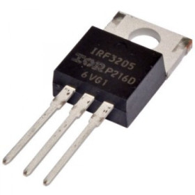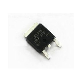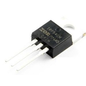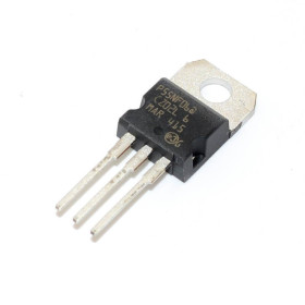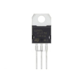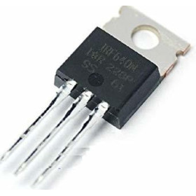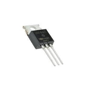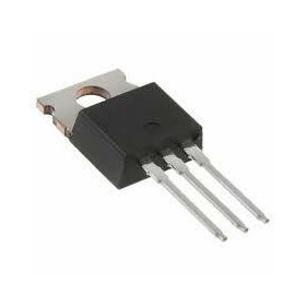

Product images are for informational purposes only and may vary slightly depending on the batch and supplier. Product specifications and prices may be subject to change without notice. We do our best to provide accurate and complete product specifications, but they may not be completely accurate. If you encounter any such situation, please let us know.
The product is intended for specialists and requires qualified and authorized personnel. The product does not include assembly/use instructions . Putting the product into operation by unqualified persons leads to the loss of the warranty according to the Terms and Conditions on the site.
The specified technical parameters (current, power, etc.) represent maximum allowable values under ideal operating conditions. For safe use and optimal lifespan, it is recommended to operate the product continuously at no more than 50% of the specified maximum values.
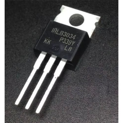
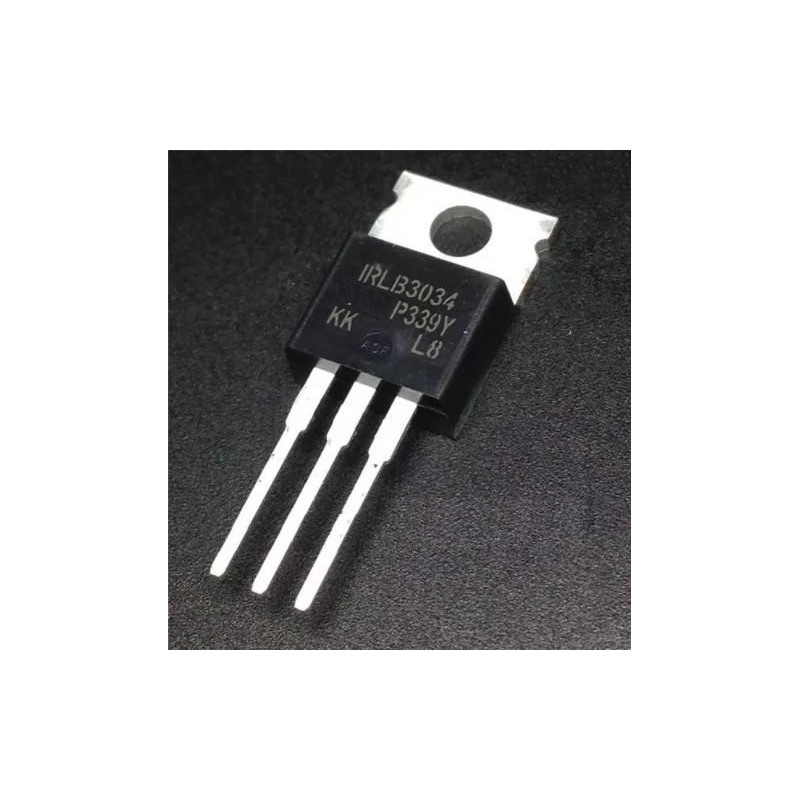
MOSFET HEXFET IRLB3034PBF, N-channel, 40V, 195A, TO-220AB
Power MOSFET for fast DC switching, ideal for converters, switching power supplies and motor control. Offers very low Rds(on) for reduced losses, high current capability, logic level drive for direct control from drivers or microcontrollers, and a TO-220 package easy to mount on a heatsink.
Buying this product earns you 0.30 RON in loyalty points.

International fast shipping within EU. Free Shipping for orders above 100 EUR in most EU countries.

We ship from our stock within 24H

You earn points with every order, worth 5%.
The HEXFET IRLB3034PBF MOSFET is an N-channel power transistor in a TO-220AB package, designed for switching high currents at voltages up to 40 V. It is used in low side static switches, in PWM brightness or speed control, in driving motors, pumps, solenoids and LED strips, in synchronous DC-DC converters, and in protection and power distribution circuits in low voltage supplies.
The transistor is optimized for logic level drive. The threshold voltage VGS(th) is between 1.0 and 2.5 V, and the on-state resistance RDS(on) is at most 2 mΩ at VGS = 4.5 V, and 1.4 mΩ typical (1.7 mΩ maximum) at VGS = 10 V. The continuous drain current is 195 A, limited by the package, and the silicon limit is 343 A. The maximum drain-source voltage is 40 V, and the maximum gate voltage is ±20 V.
The main features include the TO-220AB package with three terminals and a metal tab electrically connected to the drain, a power dissipation of up to 375 W, a maximum junction temperature of 175 °C, an input capacitance of approximately 10.3 nF, and a lead-free construction. The transistor has no power supply of its own: the load is powered from an external source, and the gate is driven with a logic level signal.
Specifications:
Drain-source voltage (VDS): 40 V
Continuous drain current (ID): 195 A, limited by the package
Drain current limited by silicon: 343 A
Transistor type: N-channel HEXFET MOSFET
Gate-source voltage (VGS): ±20 V
Threshold voltage VGS(th): 1.0 - 2.5 V
RDS(on) at VGS = 4.5 V: maximum 2 mΩ
RDS(on) at VGS = 10 V: 1.4 mΩ typical, 1.7 mΩ maximum
Power dissipation: 375 W
Input capacitance Ciss: approximately 10.3 nF
Operating temperature: -55 - 175 °C
Package: TO-220AB, 3 pins
Pinout:
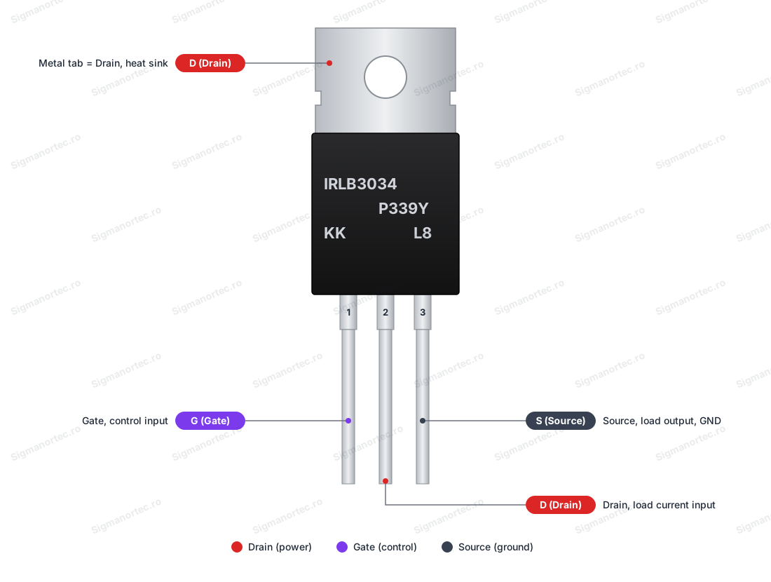
| Connector | Pin | Function |
|---|---|---|
| TO-220AB, pin 1 (left) | G (Gate) | Gate, the control input of the transistor |
| TO-220AB, pin 2 (middle) | D (Drain) | Drain, the input of the load current |
| TO-220AB, pin 3 (right) | S (Source) | Source, the output of the load current, connected to the circuit ground |
| Metal tab | D (Drain) | Electrically connected to the drain, for heat dissipation |
The pin order applies when the marked side of the package faces you and the terminals point downward.
Usage:
Identify the pins by holding the transistor with the marked side facing you and the terminals pointing down, from left to right: G, D, S.
Connect the load on the low side: the positive of the load to the positive of the power supply, the negative of the load to the drain D, and the source S to the negative of the power supply.
Connect the ground of the control circuit to the source S, otherwise the gate signal has no reference and the transistor does not switch correctly.
Drive the gate through a series resistor of about 220 ohms, and add a 10 kohm resistor between the gate and ground, which keeps the transistor off while the control circuit is in reset or its output is undefined.
Do not apply to the gate voltages higher than 20 V or lower than -20 V relative to the source, and do not exceed 40 V between drain and source.
For inductive loads, such as motors, relays or solenoids, mount a protection diode in parallel with the load, with the cathode toward the positive, because voltage spikes at turn-off can exceed 40 V.
Do not let the metal tab touch other metal parts or ground, as it is connected to the drain. When mounting on a common heatsink, use an insulator and an insulating bushing.
For high currents, calculate separately the cable cross-section, the solder joints and the heatsink. The power dissipated in the transistor is P = I x I x RDS(on), and the real current limit is set by the terminals, the PCB traces and the cooling.
Check the operation by applying a HIGH logic signal to the gate, when the load should start, then LOW, when it should stop. If the transistor heats up at moderate currents, measure the actual gate voltage in conduction.
Handle the component with anti-static precautions, as it is sensitive to electrostatic discharge.
- Type
- N-channel HEXFET MOSFET
- Operating temperature
- -55-175 °C
- Package
- TO-220AB, 3 pini
Produs destinat utilizarii in proiecte electronice, automatizari, prototipare, educatie si cercetare.
Produsul trebuie utilizat numai conform specificatiilor tehnice mentionate in descriere si/sau in documentatia produsului.
Avertismente generale de siguranta:
Nu utilizati produsul la tensiuni, curenti sau temperaturi peste valorile specificate.
Montajul si conectarea trebuie realizate de persoane cu cunostinte tehnice minime in domeniul electric/electronic.
Evitati scurtcircuitele, inversarea polaritatii si conectarea gresita a alimentarii.
Nu lasati produsul alimentat nesupravegheat in timpul testelor.
Produsul nu este jucarie si nu este destinat copiilor.
Pentru modulele electronice, se recomanda utilizarea in carcase, panouri sau montaje protejate, dupa caz.
Identificare produs:
Denumirea produsului, codul/SKU-ul si caracteristicile tehnice sunt mentionate in pagina produsului si/sau pe eticheta ambalajului.
Producator / Importator / Distribuitor:
Sigmanortec S.R.L.
Calea Bucuresti nr. 9, Targu Jiu, Gorj, Romania
E-mail: [email protected]
Website: www.sigmanortec.ro
Persoana responsabila in UE:
Sigmanortec S.R.L.
Calea Bucuresti nr. 9, Targu Jiu, Gorj, Romania
E-mail: [email protected]
Documentatie si siguranta:
Pentru informatii suplimentare, fise tehnice, declaratii de conformitate sau instructiuni, ne puteti contacta la [email protected].
Reviews (3) - Review moderation

Am cumparat vreo cateva de aici si cand am inceput sa le montez in circuit pocnesc ca floricelele la 8A (cu ditai radiatorul pe ele) si 24V (D-S) cu 9V(G-S). In datasheet este specificat ca rezista pana la 340A. La 1.4mOhm RDSon, ele ar trebui sa consume cam 89mW (nici nu e nevoie de radiator), dar ele incing radiatoarele ca focul. Am masurat Ciss si da 1.5nF, cand ar trebui sa fie aprox 10nF. Deci, rusinica. In plus, nici nu seamana poza cu ceea ce primesti. Macar ar trebui sa scrie undeva ca sunt clone sau refurbished, sa stie omul ce cumpara.
Foarte bun pentru proiecte Arduino, cu control logic. Vreau sa-l folosesc la un Spot welder. Ids>200A in puls (100...500 ms)
toate produsele cumparate de la acest shop sant excelente, livrare rapida
/*
  IRLB3034PBF logic level MOSFET test with Arduino Uno
  Board: Arduino Uno (Tools > Board > Arduino AVR Boards > Arduino Uno)
  Libraries: none needed

  Wiring (TO-220AB, marked face toward you, leads down: G, D, S from left to right):
    Arduino D9  -> 220 ohm resistor -> IRLB3034 G (Gate)
    IRLB3034 G  -> 10 kohm resistor -> Arduino GND
    IRLB3034 D  -> minus of the load (for example a 12 V LED strip)
    IRLB3034 S  -> minus of the 12 V power supply
    Arduino GND -> minus of the 12 V power supply (common ground)
    Plus of the 12 V power supply -> plus of the load

  For motors, relays or solenoids add a flyback diode across the load,
  with the cathode on +12 V.
*/

const uint8_t GATE_PIN = 9;   // Gate drive pin (PWM capable)

void setup() {
  pinMode(GATE_PIN, OUTPUT);     // Gate pin as output
  digitalWrite(GATE_PIN, LOW);   // MOSFET off at start

  Serial.begin(9600);            // Serial monitor at 9600 baud
  Serial.println(F("IRLB3034 test started"));
}

void loop() {
  // Full on: 5 V on the gate fully turns the MOSFET on
  digitalWrite(GATE_PIN, HIGH);
  Serial.println(F("MOSFET ON (100 %)"));
  delay(2000);

  // Half power with PWM (about 490 Hz on pin D9)
  analogWrite(GATE_PIN, 128);
  Serial.println(F("MOSFET PWM (50 %)"));
  delay(2000);

  // Off: gate at 0 V
  digitalWrite(GATE_PIN, LOW);
  Serial.println(F("MOSFET OFF (0 %)"));
  delay(2000);
}
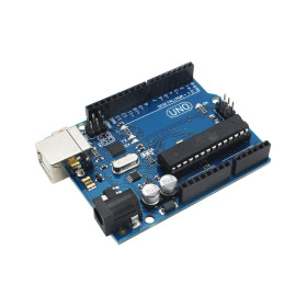
IRLB3034PBF is an N-channel HEXFET MOSFET transistor, in a TO-220AB package, designed for switching high currents at voltages up to 40 V. Being a simple MOSFET, without its own controller, it needs a microcontroller to drive its gate. In this tutorial we use an Arduino Uno R3 board, powered via USB from the computer, because its 5 V output is enough to fully open the transistor.
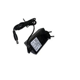
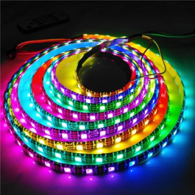
We use it to switch on and dim a 12 V 5050 LED strip, powered separately from a 12 VDC power supply through the DC barrel adapter with terminals. The same circuit can be used for motors, pumps, solenoids or relays, if you respect the voltage and current.
How it works:
An N-channel MOSFET behaves like a voltage-controlled switch. Between drain (D) and source (S) the current flows or not, depending on the voltage between gate (G) and source (S), denoted VGS. The gate draws no current in steady state, only during switching, when its input capacitance is charged or discharged.
IRLB3034PBF is optimized for logic-level drive. The threshold VGS(th) is between 1.0 and 2.5 V, and the on-resistance RDS(on) is at most 2 mΩ at VGS = 4.5 V and 1.4 mΩ typical (1.7 mΩ maximum) at VGS = 10 V. The 5 V output of the Arduino Uno fully opens it, so no gate driver is needed. The maximum gate voltage is ±20 V, and the maximum drain-source voltage is 40 V.
Drain current is 343 A limited by silicon and 195 A limited by the package. In practice, the real limit is set by the TO-220 terminals, wires and cooling, so for high currents the wiring and heatsink must be calculated separately. For a 1 m LED strip, of about 14.4 W at 12 V, the current is 14.4 W / 12 V = 1.2 A. The power dissipated in the transistor is P = I x I x RDS(on) = 1.2 x 1.2 x 0.002, that is about 3 mW, so the transistor stays cool and does not need a heatsink. The value of 14.4 W/m is typical, so check the label of your strip.
Brightness is adjusted by PWM. Pin D9 of the Arduino Uno generates a signal of about 490 Hz, so a period of about 2 ms, and the function analogWrite(9, value), with value between 0 and 255, sets how much of the period the gate is active. At 128 the duty cycle is about 50 %, the strip receives current half the time and appears to be at half brightness.
Resistor R1 of 220 ohms, in series with the gate, limits the gate charging current to about 5 V / 220 ohms = 23 mA, below the 40 mA limit of an Arduino Uno pin. Together with the input capacitance of about 10.3 nF, R1 forms a time constant of about 2.3 microseconds, negligible compared to the PWM period of about 2 ms. Resistor R2 of 10 kohms, between gate and GND, keeps the transistor off while the board resets or pin D9 is undefined, so the strip does not switch on by itself at power-up.
Connection:
Power the Arduino Uno board via the USB cable from the computer, and the LED strip separately, from a 12 VDC power supply (minimum 2 A for 1 m of strip), through the 5.5 x 2.1 mm female DC barrel adapter with terminals. The transistor switches the negative of the strip (low-side switching). The Arduino board GND and the negative of the 12 V power supply must be connected together, otherwise the signal on the gate has no reference. The D9 signal has a logic level of 5 V, so no level converter is needed. Holding the transistor with the marked face towards you and the terminals down, the order from left to right is G, D, S. The metal tab is connected to the drain, so do not let it touch other metal parts or ground.
| Product pin | Connect to | Role |
|---|---|---|
| G (Gate) | Pin D9 of the Arduino Uno board, through R1 of 220 ohms, and to R2 of 10 kohms | PWM control of the transistor |
| D (Drain) and metal tab | Negative of the LED strip | Load current input |
| S (Source) | Negative terminal of the DC barrel adapter | Load current output and common ground connection |
| R2 of 10 kohms, other end | GND pin of the Arduino Uno board | Keeps the gate at 0 V when D9 is not driving |
| GND of the Arduino Uno board | Negative terminal of the DC barrel adapter | Common ground between the board and the 12 V power supply |
| Positive terminal of the DC barrel adapter | +12 V of the LED strip | Power supply for the strip |
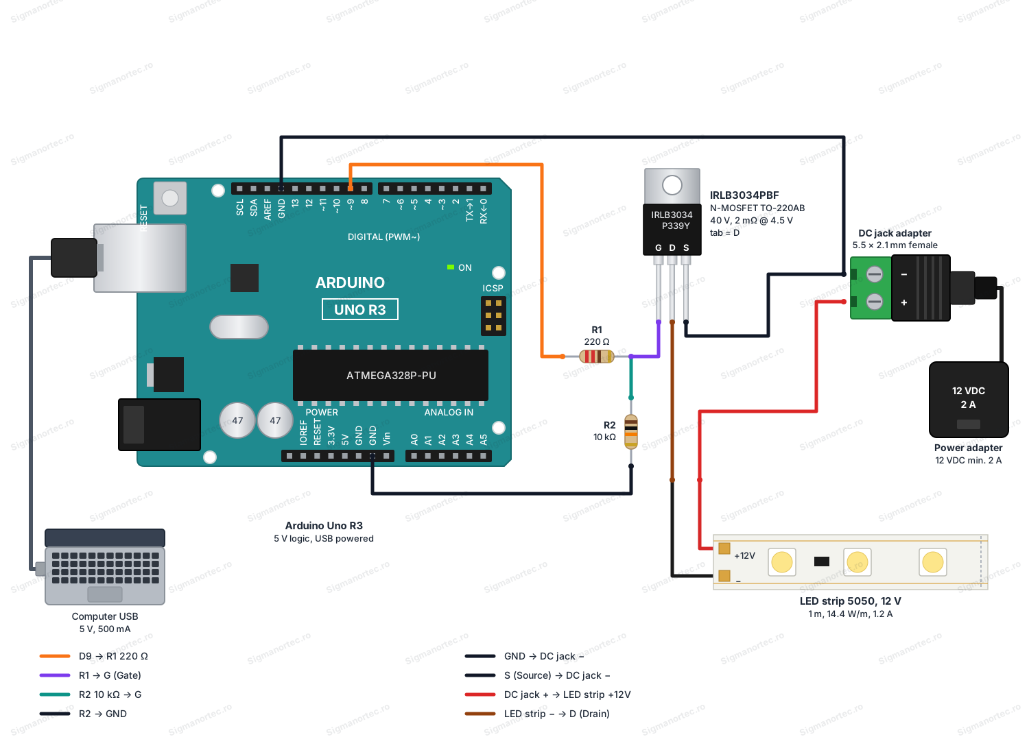
If instead of the LED strip you drive a motor, a relay or a solenoid, place a protection diode (for example 1N5819 or 1N4007) in parallel with the load, with the cathode towards +12 V. Without it, the voltage spikes generated at switch-off can exceed 40 V and damage the transistor.
Board and libraries:
In Arduino IDE select at Tools > Board the Arduino Uno board, from the Arduino AVR Boards package, which comes installed with Arduino IDE. If it is missing, install it from Boards Manager. The program uses only the basic Arduino functions, so no library needs to be installed.
Code:
The program goes through five fixed brightness steps, then smoothly increases and decreases the brightness of the strip, printing each step on the serial monitor.
/*
  IRLB3034PBF MOSFET driving a 12 V LED strip with PWM
  Board: Arduino Uno (Tools > Board > Arduino AVR Boards > Arduino Uno)
  Libraries: none, the program uses only the core Arduino functions
  Wiring (TO-220AB, marked face toward you, leads down: G, D, S from left to right):
    Arduino D9  -> R1 220 ohm -> IRLB3034 G (Gate)
    IRLB3034 G  -> R2 10 kohm -> Arduino GND (pull-down)
    IRLB3034 D  -> LED strip minus (-)
    IRLB3034 S  -> DC jack adapter minus (-)
    Arduino GND -> DC jack adapter minus (-) (common ground)
    DC jack adapter plus (+) -> LED strip +12 V
    12 VDC power supply (minimum 2 A) -> DC jack adapter
*/
const uint8_t GATE_PIN = 9;                                       // PWM pin connected to the gate through R1
const uint8_t LEVELS[] = {0, 64, 128, 192, 255};                  // Brightness steps (0 - 255)
const uint8_t LEVEL_COUNT = sizeof(LEVELS) / sizeof(LEVELS[0]);   // Number of steps
// Apply a brightness value to the gate and print it as a percentage
void setBrightness(uint8_t value) {
  analogWrite(GATE_PIN, value);                                   // Set the PWM duty cycle
  uint8_t percent = (uint8_t)(((uint16_t)value * 100) / 255);     // Convert 0 - 255 to 0 - 100 %
  Serial.print(F("Brightness step: "));
  Serial.print(value);
  Serial.print(F(" ("));
  Serial.print(percent);
  Serial.println(F(" %)"));
}
void setup() {
  pinMode(GATE_PIN, OUTPUT);                                      // Gate pin is an output
  analogWrite(GATE_PIN, 0);                                       // Start with the strip off
  Serial.begin(9600);                                             // Start the serial monitor at 9600 baud
  Serial.println(F("IRLB3034 PWM test started on pin D9"));
}
void loop() {
  // Part 1: go through the fixed brightness steps
  for (uint8_t i = 0; i < LEVEL_COUNT; i++) {
    setBrightness(LEVELS[i]);                                     // Apply the current step
    delay(1500);                                                  // Keep it for 1.5 seconds
  }
  // Part 2: fade up smoothly
  Serial.println(F("Fade up"));
  for (int value = 0; value <= 255; value += 5) {
    analogWrite(GATE_PIN, value);                                 // Increase the duty cycle
    delay(20);                                                    // Short pause between steps
  }
  // Part 3: fade down smoothly
  Serial.println(F("Fade down"));
  for (int value = 255; value >= 0; value -= 5) {
    analogWrite(GATE_PIN, value);                                 // Decrease the duty cycle
    delay(20);                                                    // Short pause between steps
  }
}
How the code works:
The GATE_PIN constant defines pin D9, which drives the gate through R1. The LEVELS array contains the five brightness levels (0, 64, 128, 192 and 255), and LEVEL_COUNT is their count, calculated automatically from the size of the array.
In setup() the GATE_PIN is configured as output with pinMode(), it is started with analogWrite(GATE_PIN, 0), so the strip is off, then the serial port is opened at 9600 baud and a startup message is printed.
In loop() the first part goes through the levels in LEVELS. For each one setBrightness() is called, which applies the value with analogWrite(), calculates the percentage and prints it, then waits 1.5 seconds.
The second part increases the brightness from 0 to 255 and decreases it back to 0 in steps of 5, with a 20 ms pause between steps, which gives a smooth fade-in and fade-out effect. At value 0 the gate stays at 0 V, and at 255 it stays permanently at 5 V.
Result:
Open the serial monitor at 9600 baud. At each step the strip changes its brightness, and the messages below appear in order, followed by the smooth fade-in and fade-out of the strip. Only the fixed steps are shown on the monitor.
IRLB3034 PWM test started on pin D9
Brightness step: 0 (0 %)
Brightness step: 64 (25 %)
Brightness step: 128 (50 %)
Brightness step: 192 (75 %)
Brightness step: 255 (100 %)
Fade up
Fade down
Brightness step: 0 (0 %)
Brightness step: 64 (25 %)
Brightness step: 128 (50 %)
Common problems:
The strip stays off at any value. The most common cause is a missing common ground or wrong pin order. Check that the Arduino GND is connected to the negative of the DC barrel adapter and that the terminals are G, D, S from left to right, with the marked face towards you.
The strip is on permanently, even at value 0. The gate may be undefined, if R2 is missing or not connected to GND, or the transistor is mounted with drain and source swapped, in which case the internal diode conducts the current. Check R2 and the position of the pins.
Nothing appears on the serial monitor. Check that the serial monitor speed is set to 9600 baud and that the Arduino Uno board is correctly selected at Tools > Board and Tools > Port.
The transistor heats up. With a 1.2 A strip it should not heat up. If it does, the load consumes much more than you calculated, or the gate does not receive 5 V, for example because of a weak wire. Measure the voltage between G and S when conducting.
The Arduino board resets or behaves strangely when driving a motor or a relay. The voltage spikes from switching off the inductive load disturb the circuit. Fit the protection diode in parallel with the load, with the cathode towards +12 V.
The strip flickers at low PWM values. At small duty cycles the average current is very small and any noise is visible. Check the connections and use short wires for the control signal.
Limitations and tips:
The maximum drain-source voltage is 40 V, so the transistor should not be used directly at mains voltages or at voltages above 40 V. Do not exceed ±20 V on the gate. The 195 A figure is a package catalog value, and in real applications the limit is set by the TO-220 terminals, wire thickness and cooling, so for currents in the tens of amps use thick cables, good solder joints and a heatsink.
The circuit in this tutorial switches the negative of the load. To switch the positive, a P-channel MOSFET or a dedicated driver is needed. The Arduino Uno drives the gate with 5 V, at which RDS(on) is at most 2 mΩ. When driven with 3.3 V the on-resistance is not guaranteed and must be verified on the real assembly.
Further, with the same circuit you can drive a pump, a fan, a small motor with a protection diode, or several LED strips in parallel, with one transistor for each color channel.