

Product images are for informational purposes only and may vary slightly depending on the batch and supplier. Product specifications and prices may be subject to change without notice. We do our best to provide accurate and complete product specifications, but they may not be completely accurate. If you encounter any such situation, please let us know.
The product is intended for specialists and requires qualified and authorized personnel. The product does not include assembly/use instructions . Putting the product into operation by unqualified persons leads to the loss of the warranty according to the Terms and Conditions on the site.
The specified technical parameters (current, power, etc.) represent maximum allowable values under ideal operating conditions. For safe use and optimal lifespan, it is recommended to operate the product continuously at no more than 50% of the specified maximum values.
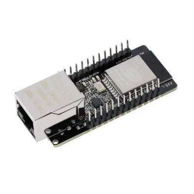
WT32-ETH01 ESP32 Gateway Module, Ethernet 10/100 Mbps, Wi-Fi, Bluetooth, 5V or 3.3V Power Supply
ESP32 module with RJ45 Ethernet port of 10/100 Mbps, Wi-Fi and Bluetooth, suitable as a gateway for automation, monitoring and IoT projects. Supports TCP and UDP in server or client mode, AT commands, OTA update over the network and software encryption, and is powered at 5 V or 3.3 V.
Buying this product earns you 3.67 RON in loyalty points.

International fast shipping within EU. Free Shipping for orders above 100 EUR in most EU countries.

We ship from our stock within 24H

You earn points with every order, worth 5%.
The WT32-ETH01 is a compact ESP32-based board that combines on the same PCB an RJ45 Ethernet port of 10/100 Mbps, Wi-Fi and Bluetooth. It is suitable as a gateway between a local network and devices with a serial port, for automation, industrial monitoring, control panels and IoT projects that need a stable wired connection. The module supports transparent data transmission between two of the four available interfaces: serial port, Wi-Fi, Ethernet and Bluetooth.
The processor is a dual-core Xtensa 32-bit LX6 ESP32, with 32 Mbit SPI flash memory and 520 KB of SRAM. The Ethernet interface is built with the LAN8720A circuit, and the network operating modes are TCP server, TCP client, UDP server and UDP client, over IPv4. The serial port speed can be set between 80 and 5000000 bps. The module accepts AT commands, OTA firmware updates over Wi-Fi or Ethernet, and AES, RSA, ECC and SHA software encryption algorithms.
The main features include the RJ45 port with LAN8720A Ethernet circuit, Wi-Fi and Bluetooth antenna integrated on the board, two 13-pin headers with 2.54 mm pitch with GPIO, ADC inputs, UART, the EN and LINK pins, the TX0, RX0 and IO0 programming pins, the POWER LED and two RXD and TXD LEDs for traffic on the secondary serial port. The module is powered at 5 V through the 5V pin or at 3.3 V through the 3V3 pin, using a single power source.
As an ESP32 board, the module is programmed from Arduino IDE (ESP32 Dev Module board), ESP-IDF or PlatformIO, through a USB-TTL adapter with 3.3 V logic connected to the TX0 and RX0 pins.
Specifications:
Supply voltage: 5 V (5V pin) or 3.3 V (3V3 pin), only one of them
Current: 80 mA in average operation, power source of minimum 500 mA
Microcontroller: dual-core Xtensa 32-bit LX6 ESP32, up to 240 MHz
Flash memory: 32 Mbit SPI
SRAM: 520 KB
Ethernet: RJ45 10/100 Mbps, LAN8720A circuit
Wi-Fi: 802.11 b/g/n, 2.4 GHz
Bluetooth: Bluetooth 4.2 (BR/EDR and BLE)
Data interfaces: Serial, Wi-Fi, Ethernet, Bluetooth
Network modes: TCP server, TCP client, UDP server, UDP client
Network protocol: IPv4, TCP/UDP
Serial baudrate: 80 - 5000000 bps
GPIO logic level: 3.3 V
Software encryption: AES, RSA, ECC, SHA
Firmware update: OTA over Wi-Fi or Ethernet
Operating temperature: -40 °C to +85 °C
Pins: Soldered or unsoldered, depending on batch, 2 x 13, 2.54 mm pitch
Dimensions: 25 x 63 x 17 mm
Layout:
| Element | Function |
|---|---|
| RJ45 port | 10/100 Mbps Ethernet connector for connecting to a router or switch via a network cable. |
| WT32-S1 module with ESP32 | Main processor, with Wi-Fi, Bluetooth and the antenna integrated on the board. |
| LAN8720A circuit | Physical Ethernet controller, connected to the ESP32 via the RMII interface. |
| Ethernet oscillator | Provides the 50 MHz clock of the LAN8720A circuit and is started by the ESP32 via the IO16 pin. |
| Voltage regulator | Produces the 3.3 V voltage of the board when the module is powered via the 5V pin. |
| POWER LED (LED1) | Lights up when the board power supply is normal. |
| RXD LED (LED3) | Lights up when there is traffic on the RXD2 line (IO5) of the secondary serial port. |
| TXD LED (LED4) | Lights up when there is traffic on the TXD2 line (IO17) of the secondary serial port. |
| LINK pin | Output for an external indicator of the network link status. |
| EN pin | High-level module enable. Pulled to GND, it resets the module. The board has no reset button. |
| IO0 pin | Selects the boot mode. Connected to GND at startup, it activates serial programming mode. Left unconnected, it runs the program from flash memory. The board has no jumper or switch, the connection is made with a wire. |
| TX0 and RX0 pins | Main serial port of the ESP32 (IO1 and IO3), used for programming and for the serial monitor. |
| Pin headers | Two rows of 13 pins with power, ground, GPIO, ADC inputs, UART and the EN and LINK pins. |
Pinout:
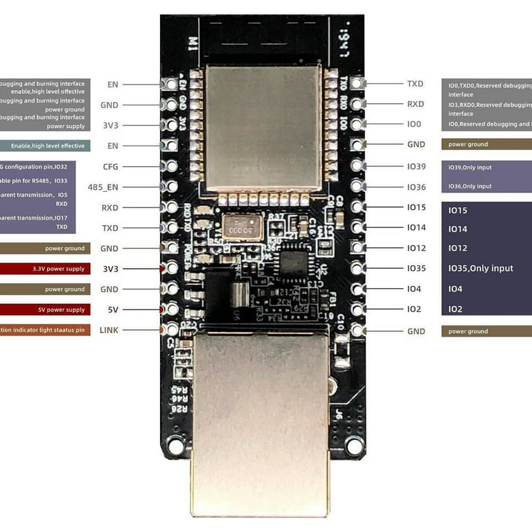
The pins are listed from the end with the RJ45 port towards the end with the antenna. Header 1 is the one containing the LINK, 5V and 3V3 pins, and header 2 is the one containing the IO0, RX0 and TX0 pins.
| Connector | Pin | Function |
|---|---|---|
| Header 1 | LINK | Output for the network link status indicator |
| Header 1 | 5V | 5 V power supply |
| Header 1 | GND | Ground |
| Header 1 | 3V3 | 3.3 V power supply |
| Header 1 | GND | Ground |
| Header 1 | TXD | IO17, TXD2, secondary serial transmission |
| Header 1 | RXD | IO5, RXD2, secondary serial reception |
| Header 1 | 485_EN | IO33, enable pin for an RS485 transceiver |
| Header 1 | CFG | IO32, marked CFG |
| Header 1 | EN | Module enable, high level. To GND it resets the module |
| Header 1 | 3V3 | 3.3 V power supply |
| Header 1 | GND | Ground |
| Header 1 | EN | Module enable, high level. To GND it resets the module |
| Header 2 | GND | Ground |
| Header 2 | IO2 | GPIO2, boot pin. Must be left free or low during programming |
| Header 2 | IO4 | GPIO4, ADC2 CH0 |
| Header 2 | IO35 | GPIO35, input only, ADC1 CH7 |
| Header 2 | IO12 | GPIO12, must be left free or low at startup |
| Header 2 | IO14 | GPIO14, ADC2 CH6 |
| Header 2 | IO15 | GPIO15, ADC2 CH3 |
| Header 2 | IO36 | GPIO36, input only, ADC1 CH0 |
| Header 2 | IO39 | GPIO39, input only, ADC1 CH3 |
| Header 2 | GND | Ground |
| Header 2 | IO0 | Boot mode. To GND at startup it activates programming. Also used for the 50 MHz Ethernet clock |
| Header 2 | RX0 | IO3, RXD0, main serial reception |
| Header 2 | TX0 | IO1, TXD0, main serial transmission |
| IO0 pin at startup | ESP32 boot mode |
|---|---|
| Not connected | Running program from flash memory (normal operation) |
| Connected to GND | Serial bootloader (program upload via TX0 and RX0) |
| ESP32 pin | Used internally for |
|---|---|
| IO16 | Starting the 50 MHz oscillator of the LAN8720A circuit |
| IO23 | MDC, Ethernet management clock |
| IO18 | MDIO, Ethernet management data |
| IO0 | 50 MHz reference clock input (REF_CLK) |
| IO19, IO21, IO22 | TXD0, TX_EN, TXD1 (RMII) |
| IO25, IO26, IO27 | RXD0, RXD1, CRS_DV (RMII) |
The pins in the last table are occupied by the Ethernet interface and are not brought out to the headers.
Usage:
Power the module either at 5 V through the 5V pin or at 3.3 V through the 3V3 pin, never through both pins at the same time, with a common ground with the rest of the circuit.
Use a stable source that can supply at least 500 mA, and do not apply a voltage higher than 5 V to the 5V pin. After powering up, the POWER LED lights up.
Respect the 3.3 V logic level. Do not apply 5 V signals to the signal pins and use a logic level converter when communicating with 5 V equipment.
For programming, connect a USB-TTL adapter with 3.3 V logic as follows: adapter TXD to RX0, adapter RXD to TX0 and GND to GND. Power the module from the 5 V pin of the adapter, connected to the 5V pin of the module.
Do not power the module from the 3.3 V output of a small adapter, because it does not provide the current needed for Wi-Fi operation.
Connect the IO0 pin to a GND pin on header 2, then power on or reset the module by briefly connecting the EN pin to GND. The module enters programming mode.
In Arduino IDE select the ESP32 Dev Module board, set the upload speed to 115200 and upload the program.
After uploading, remove the connection between IO0 and GND, then switch the power off and on again or reset the module via EN. The program starts from flash memory.
During programming and startup, leave the IO2 and IO12 pins unconnected or at low level, because their level at startup affects the ESP32 boot.
For the Ethernet connection, connect a network cable between the RJ45 port and a router or switch with DHCP, then open the serial monitor at 115200 baud and check that the module obtains an IP address.
For the Wi-Fi connection, set the network name and password through AT commands or through the application code.
Do not use the IO2, IO4, IO12, IO14 and IO15 pins as analog inputs while Wi-Fi is active, because they belong to the ADC2 converter. For analog measurements use IO35, IO36 and IO39, which are input only.
For OTA updates, make sure the module has access to the local network and use the update function built into the firmware or the espota.py utility.
For stable operation use a power source with fast start-up and short power cables, and in industrial environments keep the module within the temperature range of -40 °C to +85 °C, protected from humidity and vibration.
- Supply voltage
- 5 V sau 3.3 V
- Dimensions
- 25 x 63 x 17 mm
- Operating temperature
- -40 °C la +85 °C
- Number of pins
- 2 x 13
- Interface
- Serial, Wi-Fi, Ethernet, Bluetooth
- Logic voltage
- 3.3 V
- Current
- 80 mA in functionare medie, sursa de minimum 500 mA
- Flash memory
- 32 Mbit SPI
- Pin pitch
- 2.54 mm
- Microcontroller
- ESP32 dual-core Xtensa 32-bit LX6, pana la 240 MHz
- WiFi
- 2.4 GHz, 802.11 b/g/n
- Bluetooth
- Bluetooth 4.2 (BR/EDR si BLE)
- SRAM memory
- 520 KB
- Protocol
- IPv4, TCP/UDP
Produs destinat utilizarii in proiecte electronice, automatizari, prototipare, educatie si cercetare.
Produsul trebuie utilizat numai conform specificatiilor tehnice mentionate in descriere si/sau in documentatia produsului.
Avertismente generale de siguranta:
Nu utilizati produsul la tensiuni, curenti sau temperaturi peste valorile specificate.
Montajul si conectarea trebuie realizate de persoane cu cunostinte tehnice minime in domeniul electric/electronic.
Evitati scurtcircuitele, inversarea polaritatii si conectarea gresita a alimentarii.
Nu lasati produsul alimentat nesupravegheat in timpul testelor.
Produsul nu este jucarie si nu este destinat copiilor.
Pentru modulele electronice, se recomanda utilizarea in carcase, panouri sau montaje protejate, dupa caz.
Identificare produs:
Denumirea produsului, codul/SKU-ul si caracteristicile tehnice sunt mentionate in pagina produsului si/sau pe eticheta ambalajului.
Producator / Importator / Distribuitor:
Sigmanortec S.R.L.
Calea Bucuresti nr. 9, Targu Jiu, Gorj, Romania
E-mail: [email protected]
Website: www.sigmanortec.ro
Persoana responsabila in UE:
Sigmanortec S.R.L.
Calea Bucuresti nr. 9, Targu Jiu, Gorj, Romania
E-mail: [email protected]
Documentatie si siguranta:
Pentru informatii suplimentare, fise tehnice, declaratii de conformitate sau instructiuni, ne puteti contacta la [email protected].
/*
  WT32-ETH01 Ethernet + TCP client test

  Board (Arduino IDE, Tools > Board): ESP32 Dev Module
  Board package (Boards Manager): esp32 by Espressif Systems, versions 2.0.x or 3.x
  Boards Manager URL (File > Preferences):
    https://espressif.github.io/arduino-esp32/package_esp32_index.json
  Libraries: none to install. WiFi.h, ETH.h and WiFiClient.h come with the ESP32 package.

  Wiring (CP2102 USB to TTL adapter, 3.3 V logic):
    Adapter +5V -> module 5V pin
    Adapter GND -> module GND pin
    Adapter TXD -> module RX0
    Adapter RXD -> module TX0
    Module IO0  -> GND only while uploading, then remove it and restart the module
    RJ45 port   -> router or switch with DHCP
*/

#include <WiFi.h>
#include <ETH.h>
#include <WiFiClient.h>

// Ethernet PHY (LAN8720A) settings specific to the WT32-ETH01
#define WT_PHY_ADDR  1
#define WT_PHY_POWER 16
#define WT_PHY_MDC   23
#define WT_PHY_MDIO  18

// TCP server to connect to (change to the address of your server)
const char* serverHost = "192.168.1.100";
const uint16_t serverPort = 8080;

static bool ethConnected = false;

// Network event handler
void onEvent(WiFiEvent_t event) {
  switch (event) {
    case ARDUINO_EVENT_ETH_START:
      Serial.println("ETH started");
      ETH.setHostname("wt32-eth01");
      break;
    case ARDUINO_EVENT_ETH_CONNECTED:
      Serial.println("ETH cable connected");
      break;
    case ARDUINO_EVENT_ETH_GOT_IP:
      Serial.print("IP address: ");
      Serial.println(ETH.localIP());
      ethConnected = true;
      break;
    case ARDUINO_EVENT_ETH_DISCONNECTED:
      Serial.println("ETH disconnected");
      ethConnected = false;
      break;
    default:
      break;
  }
}

void setup() {
  Serial.begin(115200);
  delay(500);
  WiFi.onEvent(onEvent);

  // The order of the arguments changed in version 3 of the ESP32 package
#if ESP_ARDUINO_VERSION_MAJOR >= 3
  ETH.begin(ETH_PHY_LAN8720, WT_PHY_ADDR, WT_PHY_MDC, WT_PHY_MDIO, WT_PHY_POWER, ETH_CLOCK_GPIO0_IN);
#else
  ETH.begin(WT_PHY_ADDR, WT_PHY_POWER, WT_PHY_MDC, WT_PHY_MDIO, ETH_PHY_LAN8720, ETH_CLOCK_GPIO0_IN);
#endif
}

void loop() {
  if (!ethConnected) {
    delay(500);
    return;
  }

  WiFiClient client;
  if (!client.connect(serverHost, serverPort)) {
    Serial.println("TCP connection failed");
    delay(2000);
    return;
  }

  Serial.println("TCP connected, sending test payload");
  client.println("Hello from WT32-ETH01");

  // Wait up to 3 seconds for an answer
  unsigned long start = millis();
  while (client.available() == 0) {
    if (millis() - start > 3000) {
      Serial.println("Server timeout");
      client.stop();
      return;
    }
    delay(10);
  }

  // Print the answer of the server
  while (client.available()) {
    Serial.write(client.read());
  }
  client.stop();
  delay(5000);
}
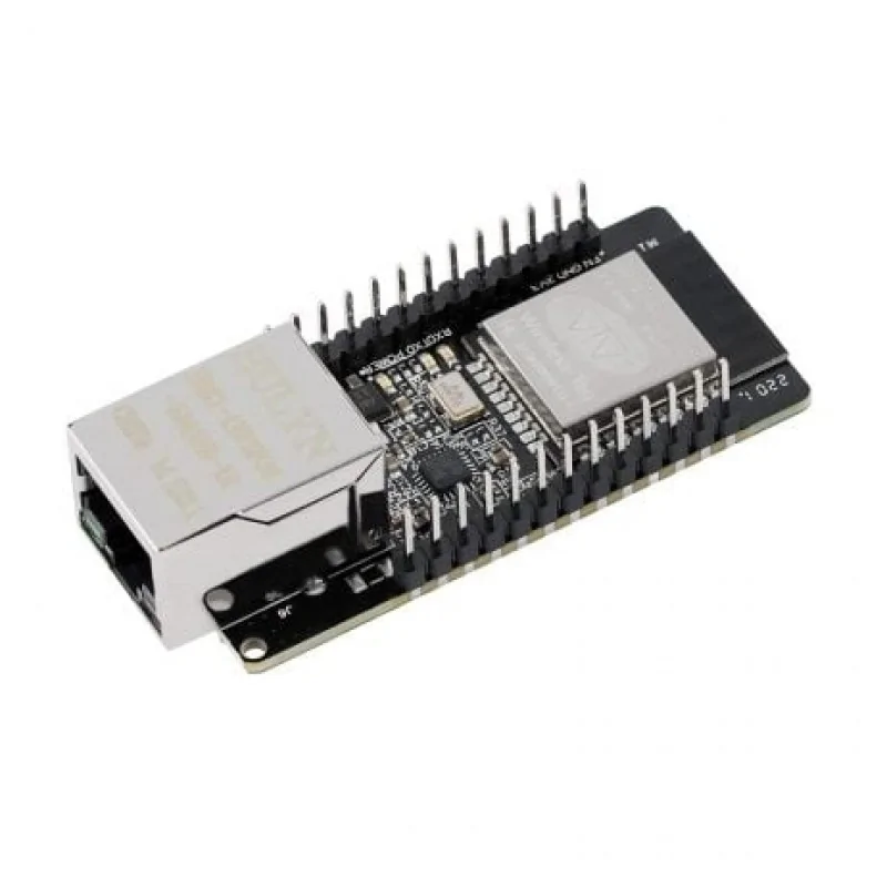
WT32-ETH01 is a board with an ESP32 and an Ethernet port, used in projects that need a wired connection more stable than Wi-Fi, for example automation nodes, gateways for serial devices or monitoring panels. In this tutorial we use the module alone, programmed from the Arduino IDE with the ESP32 Dev Module board, without any other development board.
The module has no USB port, so we program it through a CP2102 USB-TTL adapter with 3.3 V logic. At the end we will have a program that starts the Ethernet interface, displays the IP address received from the router and periodically checks that the network responds.
How it works:
The ESP32 contains the MAC controller for Ethernet, and the LAN8720A circuit on the board is the physical part (PHY) that talks to the cable. The two are connected through the RMII interface, which needs a 50 MHz reference clock. This clock comes from an oscillator on the board, started by the ESP32 through pin IO16, and enters the ESP32 on pin IO0. That is why in the program pin IO16 is declared as the power pin of the PHY and the clock is set to ETH_CLOCK_GPIO0_IN.
Pins IO23 (MDC) and IO18 (MDIO) form the management bus through which the ESP32 configures the LAN8720A, and the PHY address is 1. The actual data travels on the RMII pins IO19, IO21, IO22, IO25, IO26 and IO27, which are used internally and do not appear on the headers.
A few useful calculations. The serial port at 115200 baud transmits 10 bits for each byte (one start bit, 8 data bits and one stop bit), so approximately 115200 / 10 = 11520 bytes per second. Ethernet at 100 Mbps has a theoretical speed of 100 / 8 = 12.5 MB per second, which is over 1000 times faster. The average consumption is 80 mA, but the power source must be able to supply at least 500 mA for the current peaks of Wi-Fi and Ethernet. A USB port provides 500 mA, so it is sufficient.
Connection:
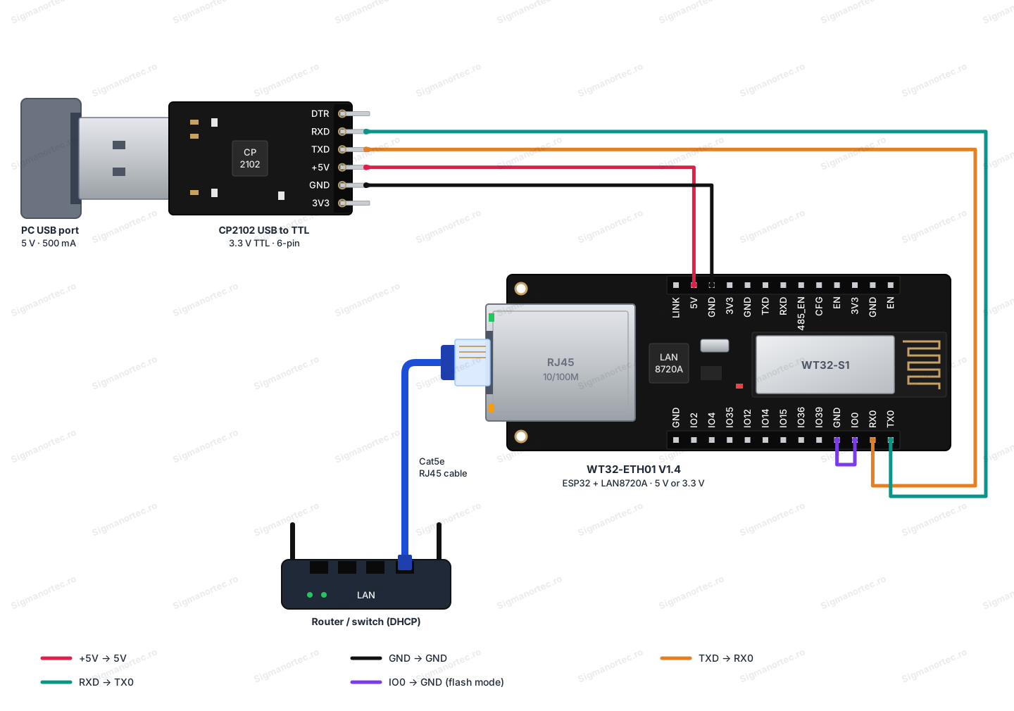
We power the module from the +5V pin of the CP2102 adapter, which passes the 5 V from USB directly through. We do not use the 3V3 pin of the adapter, because its regulator gives a small current, insufficient for an ESP32 with Wi-Fi. The signals are 3.3 V, so no level converter is needed, but never apply 5 V to the signal pins. The serial line is cross-connected: TXD of the adapter to RX0 and RXD of the adapter to TX0. Pin IO0 is connected to GND only while we upload the program.
| Product pin | Connects to | Role |
|---|---|---|
| 5V (header 1) | +5V pin of the CP2102 adapter | 5 V power from USB |
| GND (header 1, next to the 5V pin) | GND pin of the CP2102 adapter | Common ground |
| RX0 (header 2) | TXD pin of the CP2102 adapter | Serial receive, IO3 |
| TX0 (header 2) | RXD pin of the CP2102 adapter | Serial transmit, IO1 |
| IO0 (header 2) | GND pin next to IO0, on header 2 | Programming mode, only during upload |
| RJ45 port | Router or switch with DHCP, via Cat5e cable | Network connection |
| 3V3 | Not connected | Do not power from here when using the 5V pin |
Buttons, adjustments and indicators:
The board has no buttons, potentiometers, jumpers or switches. Starting in programming mode is done with a wire between IO0 and GND, and resetting is done with the EN pin. The status of the board is shown by three LEDs.
| Element | What it does | How to use it |
|---|---|---|
| IO0 - GND link | Selects the boot mode of the ESP32 | Connected at power-up, the ESP32 waits for the program over serial. Removed, it runs the program from flash. |
| EN pin | Enables or resets the module | Touched briefly to GND, it resets the module. Left free, the module stays on. |
| POWER LED (LED1) | Indicates power | It lights up when the power supply is normal. If it stays off, check the power supply and polarity. |
| RXD LED (LED3) | Indicates traffic on RXD2 (IO5) | It lights up when data passes on the RXD2 line. In the tutorial program it stays off, because that line is not used. |
| TXD LED (LED4) | Indicates traffic on TXD2 (IO17) | It lights up when data passes on the TXD2 line. In the tutorial program it stays off. |
| LINK pin | Output for the network link indicator | It can be connected to an external LED with a limiting resistor, if you want to see the status of the link. |
Programming mode. Connect the wire between IO0 and GND before powering the board or before resetting it. After the Arduino IDE finishes the upload, remove the wire and restart the power. If the serial monitor displays the message waiting for download, the wire is still connected or the board was not restarted.
Resetting. To restart the program without removing the power, touch the EN pin briefly to GND with a wire. The program restarts from the beginning and you will see the startup messages again on the serial monitor.
The POWER LED. When the adapter is connected to USB, it must light up immediately. This is the first sign that the power and ground are correct.
Board and libraries:
In the Arduino IDE, select the ESP32 Dev Module board from Tools > Board, from the esp32 package by Espressif Systems, installed from the Boards Manager. The package does not come with the Arduino IDE, so first add the address https://espressif.github.io/arduino-esp32/package_esp32_index.json under File > Preferences, at Additional boards manager URLs. The program was written for versions 2.0.x and 3.x of the package. Set the Upload Speed to 115200.
The program uses only the libraries that come with the ESP32 package (WiFi.h, ETH.h and WiFiClient.h), so no library needs to be installed from the Library Manager.
The code:
The program starts the Ethernet interface with the parameters specific to the WT32-ETH01 board, displays the network events and the IP address, and every 5 seconds attempts a TCP connection to the network gateway, that is the router, on port 80.
/*
  WT32-ETH01 Ethernet test: prints the IP address and checks the router
  Board (Arduino IDE, Tools > Board): ESP32 Dev Module
  Board package (Boards Manager): esp32 by Espressif Systems, versions 2.0.x or 3.x
  Boards Manager URL (File > Preferences):
    https://espressif.github.io/arduino-esp32/package_esp32_index.json
  Libraries: none to install. WiFi.h, ETH.h and WiFiClient.h come with the ESP32 package.
  Wiring (CP2102 USB to TTL adapter, 3.3 V logic):
    Adapter +5V -> module 5V pin (row 1)
    Adapter GND -> module GND pin next to 5V (row 1)
    Adapter TXD -> module RX0
    Adapter RXD -> module TX0
    Module IO0  -> module GND next to IO0 (row 2), only while uploading
    RJ45 port   -> router or switch with DHCP
*/
#include <WiFi.h>
#include <ETH.h>
// Ethernet PHY (LAN8720A) settings specific to the WT32-ETH01
#define WT_PHY_ADDR  1   // PHY address
#define WT_PHY_POWER 16  // GPIO16 enables the 50 MHz oscillator
#define WT_PHY_MDC   23  // Management clock pin
#define WT_PHY_MDIO  18  // Management data pin
static bool ethConnected = false;       // True after an IP address is received
static unsigned long lastCheck = 0;     // Time of the last network check
const unsigned long CHECK_INTERVAL = 5000;  // Check every 5 seconds
// Called by the system for every network event
void onEvent(WiFiEvent_t event) {
  switch (event) {
    case ARDUINO_EVENT_ETH_START:
      Serial.println("ETH started");
      ETH.setHostname("wt32-eth01");  // Name shown on the router
      break;
    case ARDUINO_EVENT_ETH_CONNECTED:
      Serial.println("ETH cable connected");
      break;
    case ARDUINO_EVENT_ETH_GOT_IP:
      Serial.print("ETH MAC: ");
      Serial.println(ETH.macAddress());
      Serial.print("IP address: ");
      Serial.println(ETH.localIP());
      Serial.print("Subnet mask: ");
      Serial.println(ETH.subnetMask());
      Serial.print("Gateway: ");
      Serial.println(ETH.gatewayIP());
      ethConnected = true;
      break;
    case ARDUINO_EVENT_ETH_DISCONNECTED:
      Serial.println("ETH cable disconnected");
      ethConnected = false;
      break;
    case ARDUINO_EVENT_ETH_STOP:
      Serial.println("ETH stopped");
      ethConnected = false;
      break;
    default:
      break;
  }
}
void setup() {
  Serial.begin(115200);  // Serial monitor on TX0 / RX0
  delay(500);
  Serial.println("WT32-ETH01 Ethernet test");
  WiFi.onEvent(onEvent);  // Register the event handler
  // The order of the arguments changed in version 3 of the ESP32 package
#if ESP_ARDUINO_VERSION_MAJOR >= 3
  ETH.begin(ETH_PHY_LAN8720, WT_PHY_ADDR, WT_PHY_MDC, WT_PHY_MDIO, WT_PHY_POWER, ETH_CLOCK_GPIO0_IN);
#else
  ETH.begin(WT_PHY_ADDR, WT_PHY_POWER, WT_PHY_MDC, WT_PHY_MDIO, ETH_PHY_LAN8720, ETH_CLOCK_GPIO0_IN);
#endif
}
void loop() {
  if (millis() - lastCheck < CHECK_INTERVAL) {
    return;  // Not time yet
  }
  lastCheck = millis();
  if (!ethConnected) {
    Serial.println("Waiting for an IP address...");
    return;
  }
  // Show the link speed and duplex mode
  Serial.print("Link: ");
  Serial.print((unsigned int)ETH.linkSpeed());
  Serial.print(" Mbps, ");
  Serial.println(ETH.fullDuplex() ? "full duplex" : "half duplex");
  // Try a TCP connection to the router on port 80 with a 3 second timeout
  WiFiClient client;
  if (client.connect(ETH.gatewayIP(), 80, 3000)) {
    Serial.println("Router reachable on port 80");
    client.stop();  // Close the connection
  } else {
    Serial.println("Router did not accept the connection on port 80");
  }
}
How the code works:
At the beginning we define the PHY parameters: WT_PHY_ADDR is address 1 of the LAN8720A circuit, WT_PHY_POWER is pin 16 which starts the oscillator, and WT_PHY_MDC and WT_PHY_MDIO are pins 23 and 18 of the management bus. The variable ethConnected stores whether we have received an IP address, and lastCheck stores the moment of the last check.
The onEvent function is called by the system for each network event. At ARDUINO_EVENT_ETH_START we set the host name with ETH.setHostname. At ARDUINO_EVENT_ETH_CONNECTED we know that the cable is connected. At ARDUINO_EVENT_ETH_GOT_IP we display the IP address, the mask and the gateway, and set ethConnected to true. At ARDUINO_EVENT_ETH_DISCONNECTED we set ethConnected to false.
In setup we start the serial monitor at 115200 baud, register the onEvent function with WiFi.onEvent and call ETH.begin. The order of the arguments of ETH.begin changed in version 3 of the ESP32 package, which is why the call is chosen with the ESP_ARDUINO_VERSION_MAJOR directive.
In loop we check every 5 seconds, using millis, whether the Ethernet is connected. If it is, we display the link speed with ETH.linkSpeed and the duplex mode, then we create a WiFiClient object and call client.connect to ETH.gatewayIP() on port 80, with a limit of 3000 ms. If the router accepts the connection, the network works completely and we close the connection with client.stop.
Result:
Open the serial monitor at 115200 baud after you have removed the IO0 - GND link and restarted the board. After a few seconds the messages below appear, with the IP address given by your router.
WT32-ETH01 Ethernet test
ETH started
ETH cable connected
ETH MAC: 24:6F:28:A1:5C:7E
IP address: 192.168.1.57
Subnet mask: 255.255.255.0
Gateway: 192.168.1.1
Link: 100 Mbps, full duplex
Router reachable on port 80
Link: 100 Mbps, full duplex
Router reachable on port 80
Common problems:
The upload stops with the error Failed to connect to ESP32. The cause is usually IO0 not connected to GND at power-up, or the TX and RX wires not cross-connected. Connect IO0 to GND, check that the TXD of the adapter goes to RX0 and RXD to TX0, then power the board again and retry the upload.
After the upload the serial monitor shows waiting for download. The wire between IO0 and GND is still connected. Remove it and restart the power.
Strange characters appear on the serial monitor. The serial monitor speed is not 115200 baud. Select this speed in the lower right corner of the monitor.
ETH started appears, but no IP address shows up. The cable is not connected, the router does not have DHCP enabled or the port is faulty. Check the cable, try another port on the router and watch whether the cable connected message appears.
The module resets by itself or freezes at startup. The power supply is insufficient or the voltage rises too slowly. Use the +5V pin of the adapter or a 5 V source with at least 500 mA, avoid powering from the 3V3 pin of the adapter and use short power wires.
The program does not compile and gives an error at ETH.begin. The installed ESP32 package is a different version from the expected one. Use a 2.0.x or 3.x version and keep the ESP32 Dev Module board selected.
Limitations and tips:
The module has a single 10/100 Mbps Ethernet port, without power over the network cable (PoE), so it always needs a separate power supply. Pins IO34 - IO39 are input only, and only IO35, IO36 and IO39 are brought out to the headers. The ADC2 inputs (IO2, IO4, IO12, IO14, IO15) cannot be read while Wi-Fi is on. Pins IO0, IO2 and IO12 are boot pins and must not be forced at startup.
The logic level is 3.3 V, so for 5 V equipment add a level converter. The module can operate between -40 °C and +85 °C, but it is good to protect it from humidity and vibration.
Further on, you can build a serial-to-Ethernet gateway using the TXD and RXD pins, a web server for controlling relays, an MQTT node for automation or a device with OTA firmware updates over the network.