
Product images are for informational purposes only and may vary slightly depending on the batch and supplier. Product specifications and prices may be subject to change without notice. We do our best to provide accurate and complete product specifications, but they may not be completely accurate. If you encounter any such situation, please let us know.
The product is intended for specialists and requires qualified and authorized personnel. The product does not include assembly/use instructions . Putting the product into operation by unqualified persons leads to the loss of the warranty according to the Terms and Conditions on the site.
The specified technical parameters (current, power, etc.) represent maximum allowable values under ideal operating conditions. For safe use and optimal lifespan, it is recommended to operate the product continuously at no more than 50% of the specified maximum values.
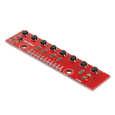
Line tracking module, QTR-8RC, with 8 IR channels, Analog, 3-5V
The 8-channel analog line tracking module, ideal for line robots, accurately detects the path through infrared sensors. It operates at 5V, provides analog outputs that are easy to read by the microcontroller, allows for fine contrast calibration and interpretation, and the QTR8 configuration covers different bandwidths for stable and fast tracking.
Shipping by Thursday 22 October
Buying this product earns you 0.76 RON in loyalty points.

International fast shipping within EU. Free Shipping for orders above 100 EUR in most EU countries.

We ship from our stock within 24H

You earn points with every order, worth 5%.
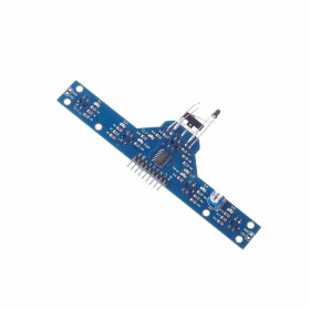
The QTR-8RC module is an array of 8 infrared reflectance sensors, designed especially for line-following robots, but also perfectly usable as a general proximity or reflectance sensor. On a compact 75 x 12.7 mm board, 8 IR emitter-receiver pairs (IR LED and phototransistor) are mounted, evenly spaced at 9.525 mm (0.375"). Each channel is completely independent, providing a separate analog output that can be measured by any analog input line on a microcontroller.
The module is compatible with Arduino Uno, Arduino Nano, STM32, ESP32, ESP8266, Raspberry Pi Pico, and any other platform with analog inputs, operating at both 3.3V and 5V. Switching from 5V to 3.3V is done through a dedicated bypass pad on the board, with no additional external components required.
Among the module’s key features are: independent analog outputs for each channel that allow direct reading via analogRead, a series-paired LED arrangement that cuts current consumption in half, a MOSFET with a default HIGH gate for LED control (the LEDON pin can be left unconnected for continuous operation or connected to a digital line for active control), total board current under 100mA at an LED current of 20–25mA per channel, and an optimal detection distance of 3mm from the surface — the correct distance is critical, as being too close to the surface prevents IR light from reflecting back to the sensor, resulting in incorrect readings.
Specifications:
Dimensions: 74.93 x 12.7 x 3.18 mm (without header pins)
Supply voltage: 3.3 - 5.0V
3.3V bypass pad: yes, available on the board
Total board current: approx. 100 mA
LED current per channel: 20 - 25 mA
Output format: analog
Number of channels: 8
Sensor spacing: 9.525 mm (0.375")
Optimal detection distance: 3 mm (0.125")
Recommended maximum distance: 9.5 mm (0.375")
Weight (without header pins): 3.09 g (0.11 oz)
Compatibility: Arduino Uno, Arduino Nano, STM32, ESP32, ESP8266, Raspberry Pi Pico, any MCU with analog input
Pinout:
| Pin | Label | Description |
|---|---|---|
| 1 | VCC | 3.3V or 5V power supply |
| 2 | GND | Common ground |
| 3 | LEDON | LED control: HIGH = on, LOW = off, default on |
| 4 | OUT1 | Analog output for sensor 1, leftmost |
| 5 | OUT2 | Analog output for sensor 2 |
| 6 | OUT3 | Analog output for sensor 3 |
| 7 | OUT4 | Analog output for sensor 4 |
| 8 | OUT5 | Analog output for sensor 5 |
| 9 | OUT6 | Analog output for sensor 6 |
| 10 | OUT7 | Analog output for sensor 7 |
| 11 | OUT8 | Analog output for sensor 8, rightmost |
Usage:
Connect VCC to the microcontroller’s 3.3V or 5V pin. For 3.3V operation, enable the bypass pad on the board.
Connect GND to the circuit’s common ground.
The LEDON pin can be left unconnected (the LEDs are on by default) or connected to 5V for safety. Connecting it to a digital line allows active LED control.
Connect OUT1-OUT8 to analog pins A0-A7. On Arduino Nano, all 8 sensors are available directly. On Arduino Uno, only 6 analog pins (A0-A5) are available, which is sufficient for most line-following applications.
Mount the module parallel to the detection surface at a distance of about 3mm. The correct distance is critical — if it is too close to the surface, some sensors will report maximum values regardless of surface color.
Read the analog values with analogRead and set a threshold between the values obtained on the white surface and on the black line.
A low value indicates a white surface with high reflectance. A high value indicates a black surface with low reflectance.
- Input Voltage
- 3 - 5 V
- Input Voltage Type
- “DC” in Romanian can mean **“de ce”**, which translates to **“why”** in English.
Produs destinat utilizarii in proiecte electronice, automatizari, prototipare, educatie si cercetare.
Produsul trebuie utilizat numai conform specificatiilor tehnice mentionate in descriere si/sau in documentatia produsului.
Avertismente generale de siguranta:
Nu utilizati produsul la tensiuni, curenti sau temperaturi peste valorile specificate.
Montajul si conectarea trebuie realizate de persoane cu cunostinte tehnice minime in domeniul electric/electronic.
Evitati scurtcircuitele, inversarea polaritatii si conectarea gresita a alimentarii.
Nu lasati produsul alimentat nesupravegheat in timpul testelor.
Produsul nu este jucarie si nu este destinat copiilor.
Pentru modulele electronice, se recomanda utilizarea in carcase, panouri sau montaje protejate, dupa caz.
Identificare produs:
Denumirea produsului, codul/SKU-ul si caracteristicile tehnice sunt mentionate in pagina produsului si/sau pe eticheta ambalajului.
Producator / Importator / Distribuitor:
Sigmanortec S.R.L.
Calea Bucuresti nr. 9, Targu Jiu, Gorj, Romania
E-mail: [email protected]
Website: www.sigmanortec.ro
Persoana responsabila in UE:
Sigmanortec S.R.L.
Calea Bucuresti nr. 9, Targu Jiu, Gorj, Romania
E-mail: [email protected]
Documentatie si siguranta:
Pentru informatii suplimentare, fise tehnice, declaratii de conformitate sau instructiuni, ne puteti contacta la [email protected].
// QTR-8RC simple analog read - Arduino Nano
// Connect OUT1-OUT8 to A0-A7
// Connect LEDON to 5V or leave unconnected
// Mount sensor at 3mm above surface
const int THRESHOLD = 500; //edit value after measurement
void setup() {
Serial.begin(9600);
}
void loop() {
for (int i = 0; i < 8; i++) {
int val = analogRead(i);
Serial.print("S");
Serial.print(i + 1);
Serial.print(": ");
Serial.print(val);
Serial.print(" (");
Serial.print(val > THRESHOLD ? "N" : "A");
Serial.println(")");
}
Serial.println("--------");
delay(300);
}