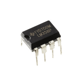

Product images are for informational purposes only and may vary slightly depending on the batch and supplier. Product specifications and prices may be subject to change without notice. We do our best to provide accurate and complete product specifications, but they may not be completely accurate. If you encounter any such situation, please let us know.
The product is intended for specialists and requires qualified and authorized personnel. The product does not include assembly/use instructions . Putting the product into operation by unqualified persons leads to the loss of the warranty according to the Terms and Conditions on the site.
The specified technical parameters (current, power, etc.) represent maximum allowable values under ideal operating conditions. For safe use and optimal lifespan, it is recommended to operate the product continuously at no more than 50% of the specified maximum values.
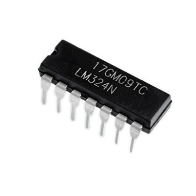
IC LM324N DIP14, Quadruple amplifier
Quad operational amplifier ideal for signal conditioning, filtering and amplification in analog projects. It offers four independent channels in a single chip, single or dual supply operation, low power consumption and good stability, and the DIP14 package allows for quick mounting on a breadboard or breadboard.
Shipping by Thursday 22 October
Buying this product earns you 0.08 RON in loyalty points.

International fast shipping within EU. Free Shipping for orders above 100 EUR in most EU countries.

We ship from our stock within 24H

You earn points with every order, worth 5%.
The LM324N integrated circuit is a quadruple operational amplifier, that is, four independent high-gain operational amplifiers, integrated in the same DIP14 package. It is one of the most widely used analog circuits for signal amplification, active filters, comparators, voltage-to-current converters, oscillators, and interfacing between sensors and digital circuits, being used both in hobbyist projects and in industrial equipment.
Each of the four amplifiers has a unity-gain bandwidth of 1 MHz, internally frequency compensated, and can operate from a single supply between 3 and 32 VDC or from a dual supply between ±1.5 and ±16 VDC. The common-mode input voltage includes ground (GND), and the output can go down almost to ground even when the circuit is powered from a single supply, which eliminates the need for a separate negative supply. The current consumed by the entire circuit is low and practically independent of the supply voltage.
Among the main characteristics are an open-loop gain of approximately 100 dB, very low input bias current, the ability to configure each of the 4 channels as an amplifier, comparator, or active filter, and compatibility with all forms of digital logic. Power is supplied on pin 4 (V+) and pin 11 (GND), according to the standard DIP14 package.
Specifications:
Supply voltage: 3 - 32 VDC (single supply) or ±1.5 - ±16 VDC (dual supply)
Supply current: 0.7 mA typical, 1.2 mA maximum, at V+ = 5 V, for the entire circuit (4 amplifiers)
Number of amplifiers: 4, independent
Open-loop gain: approximately 100 dB
Unity-gain bandwidth: 1 MHz, temperature compensated
Slew rate: 0.5 V / us
Input offset voltage: 2 mV typical, 7 mV maximum
Input bias current: 45 nA typical, 250 nA maximum
CMRR (common-mode rejection): 65 - 85 dB
PSRR (supply variation rejection): 65 - 100 dB
Output current per channel: approximately 20 mA source, 10 mA sink, at V+ = 15 V
Operating temperature range: 0 - 70 C
Package: DIP14 (PDIP, 2.54 mm pin pitch)
Dimensions: 19.3 x 6.4 mm
Pinout:
| Connector | Pin | Function |
|---|---|---|
| DIP14 | 1 | OUTPUT1 - Amplifier 1 output |
| DIP14 | 2 | INPUT1- - Inverting input of amplifier 1 |
| DIP14 | 3 | INPUT1+ - Non-inverting input of amplifier 1 |
| DIP14 | 4 | V+ - Positive supply |
| DIP14 | 5 | INPUT2+ - Non-inverting input of amplifier 2 |
| DIP14 | 6 | INPUT2- - Inverting input of amplifier 2 |
| DIP14 | 7 | OUTPUT2 - Amplifier 2 output |
| DIP14 | 8 | OUTPUT3 - Amplifier 3 output |
| DIP14 | 9 | INPUT3- - Inverting input of amplifier 3 |
| DIP14 | 10 | INPUT3+ - Non-inverting input of amplifier 3 |
| DIP14 | 11 | GND - Ground or negative supply |
| DIP14 | 12 | INPUT4+ - Non-inverting input of amplifier 4 |
| DIP14 | 13 | INPUT4- - Inverting input of amplifier 4 |
| DIP14 | 14 | OUTPUT4 - Amplifier 4 output |
Usage:
Identify pin 1 by the notch or the marked dot on the package and insert the circuit into the breadboard or socket with this orientation.
Power the circuit between pin 4 (V+) and pin 11 (GND) with a voltage between 3 and 32 VDC for single-supply operation, or connect V+ and V- relative to ground for dual-supply operation between ±1.5 and ±16 VDC.
Do not exceed the maximum voltage of 32 V between the supply pins and do not apply voltages more negative than ground to the inputs, to avoid opening the internal protection junctions.
Connect the signal to be amplified to the non-inverting or inverting input of the desired channel (for example pins 2 and 3 for the first amplifier) and set the desired gain with an external feedback network made of resistors between the output and the inverting input.
Use each of the 4 amplifiers independently, connecting unused inputs to a defined voltage level, to avoid oscillations or unnecessary extra current consumption.
Add a 100 nF decoupling capacitor as close as possible to pin 4, between V+ and GND, for stability in the presence of supply noise.
Keep in mind that the output of each amplifier can only reach about 1.5 V below V+ and cannot drop completely to 0 V when sourcing current; this behavior is normal for this type of amplifier.
For quick test setups, use the circuit in a comparator configuration or as a simple non-inverting amplifier before moving on to more complex schematics.
- Type
- Amplifier
Produs destinat utilizarii in proiecte electronice, automatizari, prototipare, educatie si cercetare.
Produsul trebuie utilizat numai conform specificatiilor tehnice mentionate in descriere si/sau in documentatia produsului.
Avertismente generale de siguranta:
Nu utilizati produsul la tensiuni, curenti sau temperaturi peste valorile specificate.
Montajul si conectarea trebuie realizate de persoane cu cunostinte tehnice minime in domeniul electric/electronic.
Evitati scurtcircuitele, inversarea polaritatii si conectarea gresita a alimentarii.
Nu lasati produsul alimentat nesupravegheat in timpul testelor.
Produsul nu este jucarie si nu este destinat copiilor.
Pentru modulele electronice, se recomanda utilizarea in carcase, panouri sau montaje protejate, dupa caz.
Identificare produs:
Denumirea produsului, codul/SKU-ul si caracteristicile tehnice sunt mentionate in pagina produsului si/sau pe eticheta ambalajului.
Producator / Importator / Distribuitor:
Sigmanortec S.R.L.
Calea Bucuresti nr. 9, Targu Jiu, Gorj, Romania
E-mail: [email protected]
Website: www.sigmanortec.ro
Persoana responsabila in UE:
Sigmanortec S.R.L.
Calea Bucuresti nr. 9, Targu Jiu, Gorj, Romania
E-mail: [email protected]
Documentatie si siguranta:
Pentru informatii suplimentare, fise tehnice, declaratii de conformitate sau instructiuni, ne puteti contacta la [email protected].