
Product images are for informational purposes only and may vary slightly depending on the batch and supplier. Product specifications and prices may be subject to change without notice. We do our best to provide accurate and complete product specifications, but they may not be completely accurate. If you encounter any such situation, please let us know.
The product is intended for specialists and requires qualified and authorized personnel. The product does not include assembly/use instructions . Putting the product into operation by unqualified persons leads to the loss of the warranty according to the Terms and Conditions on the site.
The specified technical parameters (current, power, etc.) represent maximum allowable values under ideal operating conditions. For safe use and optimal lifespan, it is recommended to operate the product continuously at no more than 50% of the specified maximum values.
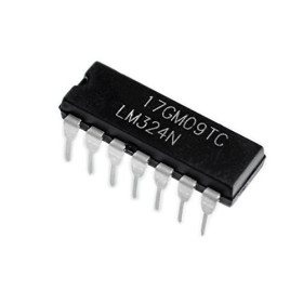
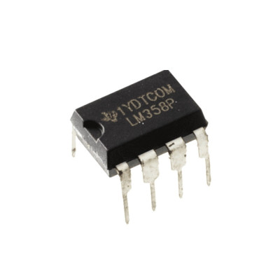
Operational Amplifier LM358P, 2 channels, DIP-8, 3-24V
Dual operational amplifier for amplification and signal conditioning projects in analog applications, offering 2 independent channels, operating at voltages between 3 and 24 V, with low consumption and good stability, suitable for filters, instrumentation amplifiers and measurement circuits in electronic systems.
Buying this product earns you 0.12 RON in loyalty points.

International fast shipping within EU. Free Shipping for orders above 100 EUR in most EU countries.

We ship from our stock within 24H

You earn points with every order, worth 5%.
LM358P is an integrated circuit with two independent operational amplifiers, in a DIP-8 package, which operates from a single supply voltage and accepts input signals down to ground level. It is used in threshold comparators, small signal amplifiers, voltage followers, active filters, signal conditioning circuits for sensors and general purpose analog circuits.
Each of the two channels has its own inverting input, non-inverting input and output, and the open loop gain is approximately 100 dB. The unity gain bandwidth is 0.7 MHz, and the consumption is low and almost independent of the supply voltage. The input range starts from ground and goes up to approximately 1.5 V below the supply voltage, and the output does not rise up to the supply voltage, but stays approximately 1.5 V below it.
Among the main features are the DIP-8 package with 2.54 mm pin pitch, suitable for breadboards and through-hole soldering, two independent channels in the same package, inputs that include the ground potential and an operating temperature range of 0 - 70 C. The power is supplied from a single 3 - 24 V source, between pins 8 (VCC) and 4 (GND).
Specifications:
Supply voltage: 3 - 24 V
Supply current: 0.35 mA per channel (typical)
Circuit type: Dual operational amplifier, single supply
Number of channels: 2
Open loop gain: 100 dB (typical)
Unity gain bandwidth: 0.7 MHz
Output current per channel: 30 mA source and 20 mA sink (typical)
Input voltage range: from ground to VCC - 1.5 V
Operating temperature: 0 - 70 C
Package: DIP-8, 2.54 mm pitch
Dimensions: 9.81 x 6.35 mm
Pinout:
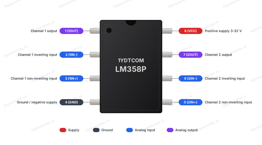
| Connector | Pin | Function |
|---|---|---|
| DIP-8 | 1 (1OUT) | Channel 1 output |
| DIP-8 | 2 (1IN-) | Channel 1 inverting input |
| DIP-8 | 3 (1IN+) | Channel 1 non-inverting input |
| DIP-8 | 4 (GND) | Ground (negative supply) |
| DIP-8 | 5 (2IN+) | Channel 2 non-inverting input |
| DIP-8 | 6 (2IN-) | Channel 2 inverting input |
| DIP-8 | 7 (2OUT) | Channel 2 output |
| DIP-8 | 8 (VCC) | Positive supply |
Usage:
Identify pin 1 by the notch of the package. With the notch facing up, pins 1 - 4 are on the left, from top to bottom, and pins 5 - 8 are on the right, from bottom to top.
Power the circuit between pin 8 (VCC) and pin 4 (GND), with a voltage between 3 and 24 V, respecting the polarity. Do not reverse the supply, as the circuit may be damaged.
Mount a 100 nF ceramic capacitor between pins 8 and 4, as close as possible to the package, for a stable supply.
Do not apply to the inputs voltages higher than the supply voltage or negative with respect to GND. Keep the input signals at least 1.5 V below VCC, otherwise the amplifier will not work correctly.
For operation as a comparator, connect a reference voltage to one input and the signal to be measured to the other, without feedback. The output goes towards ground when the non-inverting input is below the inverting one and rises towards the upper limit in the opposite case.
For operation as an amplifier, insert a feedback network between the output and the inverting input, and the gain is set by the chosen resistors.
If a channel is not used, connect it as a voltage follower, with the output to the inverting input, and the non-inverting input to ground. In this way the inputs are not left floating and the channel does not oscillate.
For stable results, use short connections, avoid large capacitive loads at the output and do not draw more than 20 mA from the output.
- Supply voltage
- 3-24 V
- Dimensions
- 9.81 x 6.35 mm
- Type
- Dual operational amplifier, single supply
- Operating temperature
- 0-70 °C
- Output current
- 30 mA source and 20 mA sink
- Power consumption
- 0.35 mA per channel
- Number of channels
- 2
- Package
- DIP-8, 2.54 mm pitch
Produs destinat utilizarii in proiecte electronice, automatizari, prototipare, educatie si cercetare.
Produsul trebuie utilizat numai conform specificatiilor tehnice mentionate in descriere si/sau in documentatia produsului.
Avertismente generale de siguranta:
Nu utilizati produsul la tensiuni, curenti sau temperaturi peste valorile specificate.
Montajul si conectarea trebuie realizate de persoane cu cunostinte tehnice minime in domeniul electric/electronic.
Evitati scurtcircuitele, inversarea polaritatii si conectarea gresita a alimentarii.
Nu lasati produsul alimentat nesupravegheat in timpul testelor.
Produsul nu este jucarie si nu este destinat copiilor.
Pentru modulele electronice, se recomanda utilizarea in carcase, panouri sau montaje protejate, dupa caz.
Identificare produs:
Denumirea produsului, codul/SKU-ul si caracteristicile tehnice sunt mentionate in pagina produsului si/sau pe eticheta ambalajului.
Producator / Importator / Distribuitor:
Sigmanortec S.R.L.
Calea Bucuresti nr. 9, Targu Jiu, Gorj, Romania
E-mail: [email protected]
Website: www.sigmanortec.ro
Persoana responsabila in UE:
Sigmanortec S.R.L.
Calea Bucuresti nr. 9, Targu Jiu, Gorj, Romania
E-mail: [email protected]
Documentatie si siguranta:
Pentru informatii suplimentare, fise tehnice, declaratii de conformitate sau instructiuni, ne puteti contacta la [email protected].
Reviews (2) - Review moderation

LM358P is an integrated circuit with two independent operational amplifiers, in a DIP-8 package. It runs from a single supply voltage and its inputs can work down to ground. It is used in threshold comparators, small signal amplifiers, voltage followers, active filters and signal conditioning circuits for sensors.
In this tutorial we use only the circuit and a 9 V battery, without a development board and without a program. We build a voltage comparator with an adjustable threshold and an LED as indicator.

How it works:
An operational amplifier has a non-inverting input (marked with plus), an inverting input (marked with minus) and an output. Its open loop gain is about 100 dB, meaning on the order of 100000 times. For this reason, without feedback, a difference of a few millivolts between the inputs drives the output to one of its limits. If the plus input has a higher voltage than the minus input, the output rises towards the upper limit. If the plus input has a lower voltage, the output falls towards ground. This is how a comparator works.
The reference voltage is obtained with a divider made of two equal resistors, R1 and R2, of 10 kΩ each, connected between +9 V and ground. The divider formula is Uref = 9 V x R2 / (R1 + R2) = 9 V x 10 kΩ / 20 kΩ = 4.5 V. This voltage reaches pin 2 of the circuit, that is the 1IN- input.
The voltage to be compared comes from the wiper of the 10 kΩ trimmer, connected to pin 3, that is the 1IN+ input. The ends of the trimmer are connected to +9 V and to ground, so the wiper can give any voltage between 0 V and 9 V. The inputs of the circuit must stay at least 1.5 V below the supply voltage, so with 9 V they stay between 0 and about 7.5 V. The 4.5 V reference falls within this limit.
The LED has its anode at +9 V, and its cathode goes through a 1 kΩ resistor R3 to the 1OUT output (pin 1). When the output is low, a current of about 6 mA flows through the LED, calculated from (9 V - 1.8 V - about 1 V) / 1 kΩ, and the LED lights up. When the output is high, it reaches only about VCC - 1.5 V, that is about 7.5 V, and the LED stays off or glows very weakly. As a result, the LED is on when the wiper is below 4.5 V and off when the wiper is above 4.5 V.
The second amplifier in the package is not used. We connect it as a voltage follower, with the 2OUT output (pin 7) connected to the 2IN- input (pin 6) and the 2IN+ input (pin 5) connected to ground. In this way its inputs do not stay floating, and the unused half does not oscillate and does not introduce noise into the supply.
Connection:
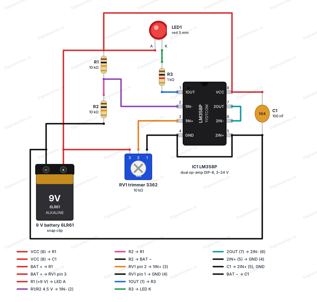
Power the circuit from a 6LR61 9 V battery with a clip. There are no logic levels in this assembly, because the output drives the LED directly. Look at the DIP-8 package from above, with the notch at the top. Pins 1 - 4 are on the left, from top to bottom, and pins 5 - 8 are on the right, from bottom to top. The 100 nF capacitor C1, marked 104, is connected between +9 V and ground, as close as possible to pins 8 and 4. Use red wire for +9 V, black wire for ground and different colours for the signal wires.
| Product pin | Connect to | Role |
|---|---|---|
| 8 (VCC) | +9 V from the battery, together with R1, end 3 of the trimmer, the LED anode and C1 | Circuit power supply |
| 4 (GND) | Battery negative, together with R2, end 1 of the trimmer and C1 | Ground |
| 2 (1IN-) | Common point between R1 and R2 | 4.5 V reference |
| 3 (1IN+) | Wiper of the 10 kΩ trimmer (trimmer pin 2) | Voltage to be compared |
| 1 (1OUT) | 1 kΩ resistor R3, then the LED cathode | Comparator output |
| 5 (2IN+) | Ground (pin 4) | Input of the unused channel |
| 6 (2IN-) | Pin 7 | Follower for the unused channel |
| 7 (2OUT) | Pin 6 | Output of the unused channel |
Check the battery polarity before connecting it. Do not apply voltages higher than the supply voltage to the inputs and do not reverse the supply, because the circuit can be damaged. The operating voltage of the circuit is 3 - 24 V, and the 9 V battery falls within this range.
Buttons, adjustments and indicators:
The assembly has no buttons, jumpers or switches. It has one adjustment, the 10 kΩ trimmer, and one indicator, the 5 mm red LED.
| Element | What it does | How to use it |
|---|---|---|
| 10 kΩ trimmer | Sets the voltage on pin 3 (1IN+), that is the signal compared with the 4.5 V reference | Turn it with a small screwdriver. Towards the end connected to +9 V the voltage on pin 3 increases, and towards the end connected to ground it decreases |
| 5 mm red LED | Shows the state of the 1OUT output | It is on when the voltage on pin 3 is below 4.5 V and off when it is above 4.5 V |
Step 1: Bring the trimmer wiper to the middle position, then connect the battery and observe the LED.
Step 2: Slowly turn the trimmer towards the end connected to +9 V until the LED turns off, then turn it back until the LED lights up again. The point where the LED switches corresponds to a voltage of about 4.5 V on pin 3.
Step 3: To see the adjustment in numbers, measure with a multimeter the voltage between pin 3 and ground while turning the trimmer. The LED switches around 4.5 V, which is exactly the voltage on pin 2. If you also measure pin 2, you should find about 4.5 V, which shows that the divider R1 and R2 works correctly.
The LED is the operating indicator. When it glows strongly, the 1OUT output is low. When it is off, the output is high. If in the off state it still glows very weakly, this is a normal effect of the output rising only to about VCC - 1.5 V.
Configuration:
The circuit has no memory and does not keep settings. The only parameters are the switching threshold, set by the divider R1 and R2, and the voltage to be compared, given by the position of the trimmer. At each power-up, the circuit works with the values given by the mounted components.
| Parameter | How it is set | Effect |
|---|---|---|
| Switching threshold (Uref) | The ratio R2 / (R1 + R2) of the divider connected to pin 2 | With R1 = R2 = 10 kΩ the threshold is 4.5 V |
| Voltage to be compared | Position of the trimmer wiper, connected to pin 3 | LED on below the threshold and off above the threshold |
| Direction of comparison | The inputs to which the reference and the signal are connected | If you swap the two signals between pins 2 and 3, the LED turns on above the threshold and turns off below it |
To change the threshold, modify the divider resistors using the formula Uref = 9 V x R2 / (R1 + R2). For example, with R1 = 10 kΩ and R2 = 20 kΩ you get 6 V. Keep the threshold below about 7.5 V, otherwise the input goes outside the operating range of the circuit.
Usage example:
Application: LED voltage threshold indicator. Keep R1 = R2 = 10 kΩ, so the threshold is 4.5 V, and the trimmer simulates the signal to be measured.
Connect the 9 V battery and a multimeter between pin 3 and ground. Turn the trimmer until the multimeter shows about 3 V. The LED must be on.
Then turn the trimmer towards the end connected to +9 V until the multimeter shows about 6 V. The LED must be off.
Slowly return towards 4.5 V. The LED switches around this value, which shows that the assembly works as a comparator with a fixed threshold. For a real application, replace the trimmer with a divider or with a sensor that gives a voltage between 0 and 7.5 V.
Common problems:
The LED never lights up. The usual cause is the LED mounted in reverse or wrong pin numbering. Check that the anode goes to +9 V and that pin 1 is the one next to the notch, then measure the voltage on pin 3 and bring it below 4.5 V.
The LED always stays off. The trimmer wiper may be connected incorrectly, or the trimmer ends may be reversed compared to what you expect. Measure the voltage on pin 3 and check that it varies between 0 and 9 V when you turn the trimmer.
The LED glows weakly when it should be off. This is normal behaviour, because the output rises only to about VCC - 1.5 V and leaves a small voltage across the LED.
The LED flickers around the threshold. The comparator has no hysteresis, and noise on the input can switch the output several times. Turn the trimmer more slowly, check the 100 nF C1 close to pins 8 and 4, and if needed add a feedback resistor between the output and the non-inverting input.
The circuit shows no sign of life or gets hot. Check the battery polarity and that pin 8 is at +9 V and pin 4 is at ground. A reversed supply can damage the circuit.
Limitations and tips:
LM358P works with a supply of 3 - 24 V and in the temperature range 0 - 70 C. The output does not reach the supply voltage, but stays about 1.5 V below it, and the inputs must stay at least 1.5 V below VCC. The bandwidth is 0.7 MHz, so the circuit is suitable for slow signals, not for fast signals.
The output current is on the order of 20 mA, enough for an LED or for driving a power stage, but not for large loads. Leaving the inputs of the unused channel unconnected can produce oscillations, which is why we connect it as a follower.
With the same circuit you can further build a comparator with hysteresis, a non-inverting amplifier for a sensor, a voltage follower or a first and second order active filter.