

Product images are for informational purposes only and may vary slightly depending on the batch and supplier. Product specifications and prices may be subject to change without notice. We do our best to provide accurate and complete product specifications, but they may not be completely accurate. If you encounter any such situation, please let us know.
The product is intended for specialists and requires qualified and authorized personnel. The product does not include assembly/use instructions . Putting the product into operation by unqualified persons leads to the loss of the warranty according to the Terms and Conditions on the site.
The specified technical parameters (current, power, etc.) represent maximum allowable values under ideal operating conditions. For safe use and optimal lifespan, it is recommended to operate the product continuously at no more than 50% of the specified maximum values.
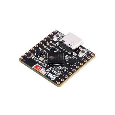
ESP32-S3-Matrix development board, 8x8 RGB matrix, 6-DOF IMU
Compact solution for IoT projects, robotics, and interactive light effects, with ESP32-S3 dual-core 240 MHz and Wi-Fi plus Bluetooth 5 LE Mesh connectivity. It integrates an 8x8 RGB matrix with addressable WS2812 LEDs for animations and displays, a 6-DOF QMI8658 IMU for motion and orientation detection, easy power supply and programming via USB-C, extendable through Dout pin and 17 multifunctional GPIOs.
Shipping by Wednesday 16 September

International fast shipping within EU. Free Shipping for orders above 100 EUR in most EU countries.

We ship from our stock within 24H

You earn points with every order, worth 5%.
The ESP32-S3-Matrix development board is a compact and high-performance solution designed for IoT projects, robotics, motion control, and interactive lighting effects. At its core is the ESP32-S3FH4R2 microcontroller, with a dual-core Xtensa LX7 processor running at 240 MHz, Wi-Fi 802.11 b/g/n connectivity, and Bluetooth 5 LE with Mesh support, offering an excellent balance between performance and small size.
The board integrates an 8x8 RGB matrix consisting of 64 individually addressable WS2812 LEDs, controlled via GPIO14, ideal for displays, animations, and complex lighting effects. The QMI8658C inertial sensor adds 6 degrees of freedom – a 3-axis accelerometer and a 3-axis gyroscope – communicating via I2C, making it suitable for motion detection, orientation, and stabilization applications.
Available memory includes 512KB SRAM, 384KB ROM, 2MB PSRAM, and 4MB Flash, sufficient for complex embedded applications. Power is supplied at 5V through the USB-C port, with an LDO regulator ME6217C33M5G providing stable 3.3V output at up to 800mA. The 17 GPIO pins support SPI, I2C, UART, ADC, and PWM, and a dedicated Dout pin allows extension of the RGB matrix with additional modules.
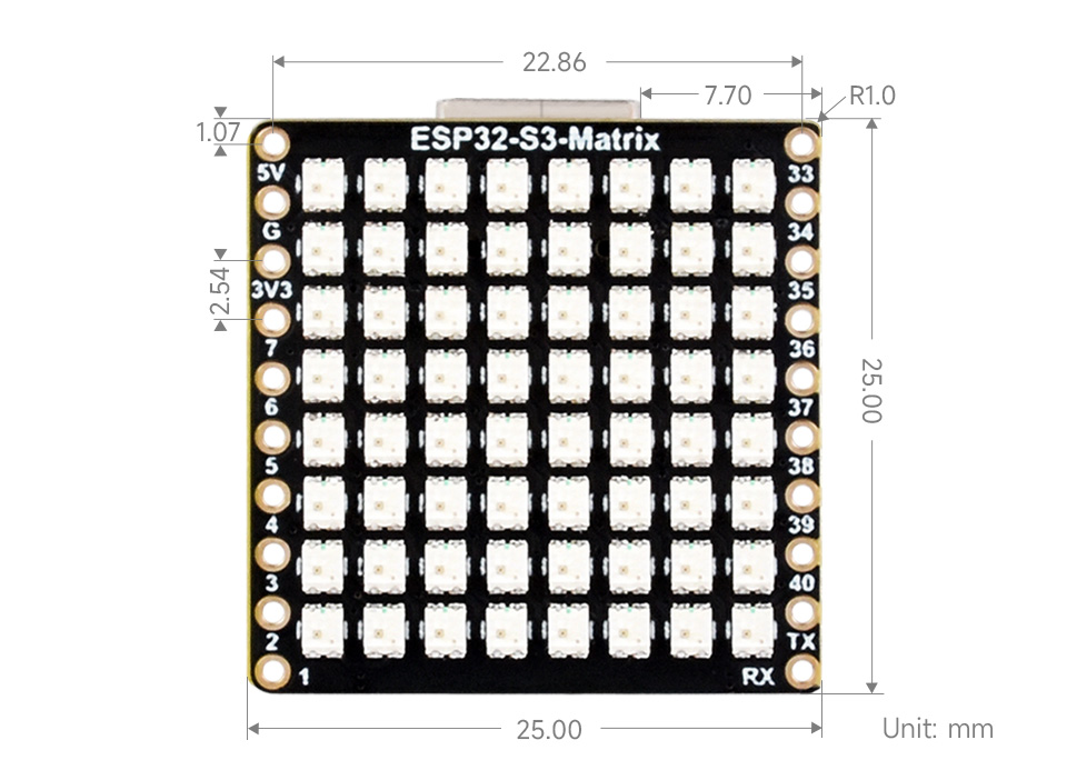
With dimensions of only 25 x 25 mm and a weight of approximately 1g, the board easily integrates into any project and features RESET and BOOT buttons for quick programming and debugging.
Specifications:
Microcontroller: ESP32-S3FH4R2, dual-core Xtensa LX7 at 240 MHz
Memory: 512KB SRAM, 384KB ROM, 2MB PSRAM, 4MB Flash
Wireless: Wi-Fi 802.11 b/g/n (2.4 GHz), Bluetooth 5 LE and Bluetooth Mesh
LED Matrix: 8×8 RGB (64 WS2811/WS2812 LEDs), controlled via GPIO14
IMU: QMI8658C, 3-axis accelerometer and 3-axis gyroscope (I2C)
Interfaces: USB-C (power and programming), 17 x GPIO (SPI, I2C, UART, ADC, PWM)
Power: 5 VDC via USB or pins
Buttons: RESET, BOOT
Dimensions: 25 x 25 mm
Weight: 1g
Layout:
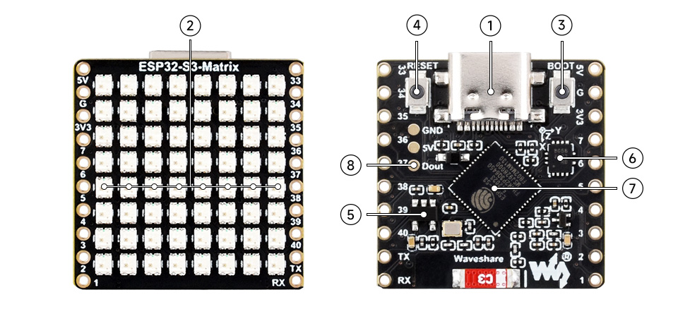
1. USB-C connector
2. 8×8 RGB LED matrix
3. BOOT button: press during reset to enter download mode
4. RESET button
5. ME6217C33M5G: low dropout regulator, 800 mA (max)
6. QMI8658: 6-axis IMU (3-axis accelerometer, 3-axis gyroscope)
7. ESP32-S3: dual-core processor, operating frequency up to 240 MHz
8. Dout pin for RGB matrix extension
Pinout:
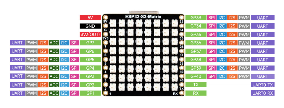
| Pin | Function | Description |
|---|---|---|
| 5V | Power | 5V power input |
| GND | Ground | Ground reference |
| 3V3(OUT) | 3.3V Output | 3.3V voltage output |
| GPIO7 | GPIO / UART / PWM / I2S / ADC / I2C / SPI | Multipurpose pin |
| GPIO6 | GPIO / UART / PWM / I2S / ADC / I2C / SPI | Multipurpose pin |
| GPIO5 | GPIO / UART / PWM / I2S / ADC / I2C / SPI | Multipurpose pin |
| GPIO4 | GPIO / UART / PWM / I2S / ADC / I2C / SPI | Multipurpose pin |
| GPIO3 | GPIO / UART / PWM / I2S / ADC / I2C / SPI | Multipurpose pin |
| GPIO2 | GPIO / UART / PWM / I2S / ADC / I2C / SPI | Multipurpose pin |
| GPIO1 | GPIO / UART / PWM / I2S / ADC / I2C / SPI | Multipurpose pin |
| GPIO33 | GPIO / SPI / I2C / I2S / PWM / UART | Multipurpose pin |
| GPIO34 | GPIO / SPI / I2C / I2S / PWM / UART | Multipurpose pin |
| GPIO35 | GPIO / SPI / I2C / I2S / PWM / UART | Multipurpose pin |
| GPIO36 | GPIO / SPI / I2C / I2S / PWM / UART | Multipurpose pin |
| GPIO37 | GPIO / SPI / I2C / I2S / PWM / UART | Multipurpose pin |
| GPIO38 | GPIO / SPI / I2C / I2S / PWM / UART | Multipurpose pin |
| GPIO39 | GPIO / SPI / I2C / I2S / PWM / UART | Multipurpose pin |
| GPIO40 | GPIO / SPI / I2C / I2S / PWM / UART | Multipurpose pin |
| TX | UART0 TX | Serial transmission |
| RX | UART0 RX | Serial reception |
Usage:
Open Arduino IDE and go to File > Preferences.
In the "Additional Boards Manager URLs" field, add the following link: https://espressif.github.io/arduino-esp32/package_esp32_index.json
Go to Tools > Board > Boards Manager, search for "esp32 by Espressif Systems" and install the package.
After installation, select the board from Tools > Board > ESP32 Arduino > ESP32S3 Dev Module.
Connect the board to the PC via USB-C and select the correct port from Tools > Port.
To enter download mode (if the board is not detected automatically), press and hold the BOOT button, press RESET, then release BOOT. Alternatively, hold the BOOT button while connecting to the PC.
Upload the desired sketch using the Upload button in Arduino IDE.
Dimensions diagram:
Documentation:
- Microcontroller
- ESP32-S3
- Display
- Matrice RGB 8x8
- Integrated sensor
- IMU 6-DOF
Produs destinat utilizarii in proiecte electronice, automatizari, prototipare, educatie si cercetare.
Produsul trebuie utilizat numai conform specificatiilor tehnice mentionate in descriere si/sau in documentatia produsului.
Avertismente generale de siguranta:
Nu utilizati produsul la tensiuni, curenti sau temperaturi peste valorile specificate.
Montajul si conectarea trebuie realizate de persoane cu cunostinte tehnice minime in domeniul electric/electronic.
Evitati scurtcircuitele, inversarea polaritatii si conectarea gresita a alimentarii.
Nu lasati produsul alimentat nesupravegheat in timpul testelor.
Produsul nu este jucarie si nu este destinat copiilor.
Pentru modulele electronice, se recomanda utilizarea in carcase, panouri sau montaje protejate, dupa caz.
Identificare produs:
Denumirea produsului, codul/SKU-ul si caracteristicile tehnice sunt mentionate in pagina produsului si/sau pe eticheta ambalajului.
Producator / Importator / Distribuitor:
Sigmanortec S.R.L.
Calea Bucuresti nr. 9, Targu Jiu, Gorj, Romania
E-mail: [email protected]
Website: www.sigmanortec.ro
Persoana responsabila in UE:
Sigmanortec S.R.L.
Calea Bucuresti nr. 9, Targu Jiu, Gorj, Romania
E-mail: [email protected]
Documentatie si siguranta:
Pentru informatii suplimentare, fise tehnice, declaratii de conformitate sau instructiuni, ne puteti contacta la [email protected].
// Test: light up all 64 LEDs on the 8x8 RGB matrix in red
#include <Adafruit_NeoPixel.h>
#define LED_PIN 14
#define LED_COUNT 64
Adafruit_NeoPixel matrix(LED_COUNT, LED_PIN, NEO_GRB + NEO_KHZ800);
void setup() {
matrix.begin();
matrix.setBrightness(40);
matrix.fill(matrix.Color(255, 0, 0)); // red
matrix.show();
}
void loop() {}