Product images are for informational purposes only and may vary slightly depending on the batch and supplier. Product specifications and prices may be subject to change without notice. We do our best to provide accurate and complete product specifications, but they may not be completely accurate. If you encounter any such situation, please let us know.
The product is intended for specialists and requires qualified and authorized personnel. The product does not include assembly/use instructions . Putting the product into operation by unqualified persons leads to the loss of the warranty according to the Terms and Conditions on the site.
The specified technical parameters (current, power, etc.) represent maximum allowable values under ideal operating conditions. For safe use and optimal lifespan, it is recommended to operate the product continuously at no more than 50% of the specified maximum values.
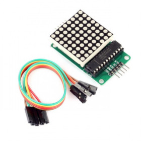
8x8 LED matrix, MAX7219, Red, SMD
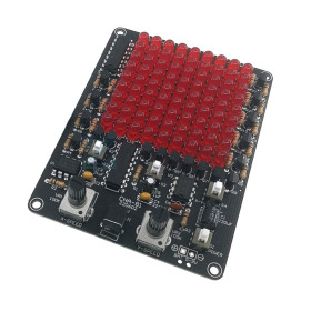
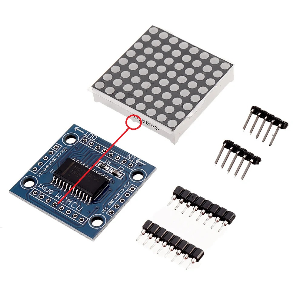
8x8 LED matrix with red LEDs, ideal for simple displays, texts, symbols and animations in projects with Arduino or other boards. Includes MAX7219 driver for easy control via SPI interface at 5V, offers 64 LEDs with 3mm pixel in a compact 32x32mm format. Depending on the batch, it may come with the display glued or not and with variable connection accessories.
Shipping by Thursday 22 October
Buying this product earns you 0.40 RON in loyalty points.

International fast shipping within EU. Free Shipping for orders above 100 EUR in most EU countries.

We ship from our stock within 24H

You earn points with every order, worth 5%.
The 8x8 LED matrix with MAX7219 driver is a compact display module designed for electronics and automation projects where short messages, symbols, animations, or visual indicators are needed. The module integrates 64 red LEDs arranged in an 8-row by 8-column layout, each pixel having a diameter of 3mm, and the active area of the matrix measures 32 x 32mm. It is powered at 5V, and communication with the development board is done via the SPI interface, which means only three signal lines are required for full control.
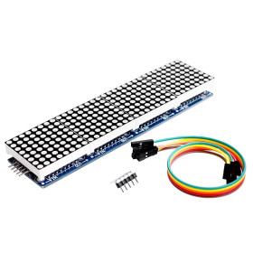
The major advantage of this module is the MAX7219 driver circuit, which takes over the entire multiplexing and image retention task. The microcontroller no longer needs to constantly refresh the display, but only sends data when the content changes, freeing up important processing resources. The driver allows brightness adjustment in 16 steps directly from software and includes a power-saving mode in which the display can be turned off without losing the data stored in internal memory. Another strong point is the cascading capability, as multiple modules can be connected in series through the output connector, making it possible to create long banner-style displays for scrolling text.
The module is compatible with Arduino UNO, Nano, Mega and Pro Mini boards, as well as ESP32, ESP8266, STM32, Raspberry Pi and Raspberry Pi Pico, or other development platforms that have SPI or configurable digital pins. For boards operating at 3.3V, the control logic generally works correctly, but the module must still be powered at 5V for optimal brightness. On the software side, there are three commonly used free libraries. LedControl is the simplest and most suitable for a single module, where you display symbols, digits and custom drawings, offering direct control over each LED, row, or column. MD_MAX72XX is a more efficient option, with support for hardware SPI and a built-in font. MD_Parola sits on top of MD_MAX72XX and is the right choice for scrolling text and ready-made animation effects, typically for banners made from multiple cascaded modules.
Typical applications include digital clocks, counters, status indicators for automation systems, display panels for short messages, retro games such as Snake or Tetris, as well as educational projects for learning SPI communication and the multiplexing principle. Current consumption depends directly on the number of LEDs lit simultaneously and the brightness level set, which is why an external power supply capable of delivering sufficient current is recommended when using multiple cascaded modules.
Important note:
Depending on the batch received from the supplier, the module may come with the display soldered or not, with one or two 90-degree pin headers, with or without a Dupont wire set. If, when powered, the LEDs light up randomly with no relation to the image sent from the code, it means the matrix is mounted upside down. Turn off the power, remove the matrix from the socket, rotate it 180 degrees, and reinsert it, after which the display will work correctly.
Currently, the correct orientation is with the side text on the matrix on the opposite side from the IN and OUT markings.
Specifications:
Supply voltage: 5V
Driver operating voltage range: 4.0V - 5.5V
Interface: SPI, 3 signal wires
Maximum serial clock frequency: 10MHz
Driver: MAX7219
Matrix type: 1088AS or equivalent
Matrix configuration: cathode on row, anode on column
LED color: Red
Wavelength: 625 - 630nm
LED forward voltage: 2.1V - 2.5V
LED forward current: 20mA
Number of LEDs: 64
Pixel size: 3mm
Matrix dimensions: 32 x 32mm
Matrix height: 8mm
LED arrangement: 8 x 8
Front mask color: Black
Brightness adjustment steps: 16
Shutdown current: 150uA
Maximum current per segment: 100mA
Maximum current per digit line: 500mA
Driver internal memory: 8 x 8 static RAM
Cascading: Yes, via DOUT pin
Connector pitch: 2.54mm
Mounting holes: 4 x M3
Operating temperature: 0°C - 70°C
Storage temperature: -65°C - 150°C
Pinout:
Input connector:
| Pin | Name | Description |
|---|---|---|
| 1 | VCC | 5V power supply |
| 2 | GND | Common ground |
| 3 | DIN | Data In, serial data input |
| 4 | CS | Chip Select, module selection (also called LOAD) |
| 5 | CLK | Clock, timing signal |
Output connector (cascading):
| Pin | Name | Description |
|---|---|---|
| 1 | VCC | 5V power supply to the next module |
| 2 | GND | Common ground |
| 3 | DOUT | Data Out, data output to the next module |
| 4 | CS | Common Chip Select |
| 5 | CLK | Common Clock |
Usage:
Check the package contents and, if the matrix is not soldered onto the driver board, insert it carefully into the socket, observing the correct orientation indicated by the marking on the PCB.
Connect the module’s VCC pin to the 5V output of the development board and the GND pin to its ground.
Connect the DIN, CLK and CS pins according to the wiring table, depending on the chosen library.
Install the desired library in Arduino IDE from Library Manager, LedControl for drawings and pixel control or MD_Parola for scrolling text.
Upload the test code and verify that the LEDs light up across the entire matrix surface.
If the LEDs light up randomly and the image does not correspond at all to what you sent from the code, turn off the power, remove the matrix from the socket, rotate it 180 degrees and reinsert it.
If you use MD_MAX72XX or MD_Parola and the text appears mirrored or incorrectly segmented, change the hardware type constant between FC16_HW and GENERIC_HW.
Adjust the brightness in software to the desired level, keeping in mind that higher values significantly increase current consumption.
For cascading, connect the DOUT, CS and CLK pins from the output of the first module to the DIN, CS and CLK pins of the input of the second module, then update the total number of devices in the code.
If you use more than two modules, power the assembly from a stabilized external 5V supply and connect the supply ground to the development board ground.
Arduino UNO connection:
Software SPI, for the LedControl library (by Eberhard):
| MAX7219 Module | Arduino UNO R3 | Notes |
|---|---|---|
| VCC | 5V | Module power supply |
| GND | GND | Common ground |
| DIN | Digital pin 12 | Serial data input |
| CS | Digital pin 10 | Chip Select (LOAD) |
| CLK | Digital pin 11 | Clock signal |
- Model
- MAX7219
Produs destinat utilizarii in proiecte electronice, automatizari, prototipare, educatie si cercetare.
Produsul trebuie utilizat numai conform specificatiilor tehnice mentionate in descriere si/sau in documentatia produsului.
Avertismente generale de siguranta:
Nu utilizati produsul la tensiuni, curenti sau temperaturi peste valorile specificate.
Montajul si conectarea trebuie realizate de persoane cu cunostinte tehnice minime in domeniul electric/electronic.
Evitati scurtcircuitele, inversarea polaritatii si conectarea gresita a alimentarii.
Nu lasati produsul alimentat nesupravegheat in timpul testelor.
Produsul nu este jucarie si nu este destinat copiilor.
Pentru modulele electronice, se recomanda utilizarea in carcase, panouri sau montaje protejate, dupa caz.
Identificare produs:
Denumirea produsului, codul/SKU-ul si caracteristicile tehnice sunt mentionate in pagina produsului si/sau pe eticheta ambalajului.
Producator / Importator / Distribuitor:
Sigmanortec S.R.L.
Calea Bucuresti nr. 9, Targu Jiu, Gorj, Romania
E-mail: [email protected]
Website: www.sigmanortec.ro
Persoana responsabila in UE:
Sigmanortec S.R.L.
Calea Bucuresti nr. 9, Targu Jiu, Gorj, Romania
E-mail: [email protected]
Documentatie si siguranta:
Pentru informatii suplimentare, fise tehnice, declaratii de conformitate sau instructiuni, ne puteti contacta la [email protected].
Reviews (5) - Review moderation

Super! este varianta FC16_HW
Sunt foarte bune , chir toate produsele vandute la ei pe site sunt de calitate !! De aceea voi continua sa cumpar de la ei !!!
Modulul FC-16 este ceea ce cautam pentru proiectul meu. Am format o matrice de leduri se 16X16 cu 4 module din astea.
_
Ok
#include <LedControl.h>
//by Eberhard
// DIN = pin 12, CLK = pin 11, CS = pin 10, number of devices = 1
LedControl lc = LedControl(12, 11, 10, 1);
byte smiley[8] = {
B00111100,
B01000010,
B10100101,
B10000001,
B10100101,
B10011001,
B01000010,
B00111100
};
void setup() {
// Wake up the MAX7219 from power saving mode
lc.shutdown(0, false);
// Set brightness level, range 0 to 15
lc.setIntensity(0, 8);
// Clear the display
lc.clearDisplay(0);
}
void loop() {
// Draw the smiley pattern row by row
for (int row = 0; row < 8; row++) {
lc.setRow(0, row, smiley[row]);
}
delay(1000);
lc.clearDisplay(0);
delay(500);
// Light up all LEDs one by one
for (int row = 0; row < 8; row++) {
for (int col = 0; col < 8; col++) {
lc.setLed(0, row, col, true);
delay(30);
}
}
delay(500);
lc.clearDisplay(0);
delay(500);
}