

Product images are for informational purposes only and may vary slightly depending on the batch and supplier. Product specifications and prices may be subject to change without notice. We do our best to provide accurate and complete product specifications, but they may not be completely accurate. If you encounter any such situation, please let us know.
The product is intended for specialists and requires qualified and authorized personnel. The product does not include assembly/use instructions . Putting the product into operation by unqualified persons leads to the loss of the warranty according to the Terms and Conditions on the site.
The specified technical parameters (current, power, etc.) represent maximum allowable values under ideal operating conditions. For safe use and optimal lifespan, it is recommended to operate the product continuously at no more than 50% of the specified maximum values.
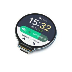
Waveshare ESP32-S3 development board, capacitive touch, round IPS LCD, 2.8 inch, 480x480, WiFi and Bluetooth
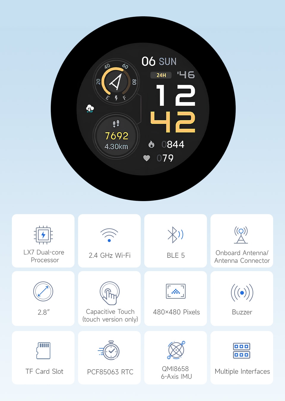
Development board with ESP32-S3 and a 2.8-inch round capacitive touchscreen, 480x480, ideal for HMI interfaces, dashboard panels, and IoT projects with a compact display. It offers 2.4GHz WiFi and Bluetooth 5, generous 16MB Flash and 8MB PSRAM for smooth graphics with LVGL, includes microSD, RTC, and a 6-axis IMU sensor, and supports easy programming via USB-C.
Buying this product earns you 19.31 RON in loyalty points.

International fast shipping within EU. Free Shipping for orders above 100 EUR in most EU countries.

We ship from our stock within 24H

You earn points with every order, worth 5%.
The Waveshare ESP32-S3-Touch-LCD-2.8C development board integrates an ESP32-S3 microcontroller and a 2.8-inch round capacitive touchscreen with a 480 x 480 resolution, making it suitable for HMI graphical interfaces, smartwatches, DIY dashboards, and other applications that require a compact display and wireless connectivity.
The board is built around the 32-bit dual-core Xtensa LX7 processor, with a clock speed of up to 240 MHz, and provides 2.4GHz WiFi (802.11 b/g/n) and Bluetooth 5 (LE) via the integrated antenna. Memory includes 512KB SRAM, 384KB ROM, 16MB Flash, and 8MB PSRAM, enough to run graphical libraries such as LVGL smoothly. The display uses the ST7701 controller over a parallel RGB interface, and the panel supports 262K colors, but due to ESP32-S3 limitations it is practically used in RGB565 format, meaning 65K colors. Touch control is handled by the GT911 chip over I2C, with interrupt support.
The board also includes a QMI8658 6-axis orientation sensor (3-axis gyroscope and 3-axis accelerometer), a PCF85063 RTC circuit with a separate connector for a backup battery, a buzzer, a TF card slot, a charger management circuit for a 3.7V Li-Ion/Li-Po battery with an MX1.25 connector and battery voltage measurement. Power and programming are handled through two USB Type-C ports, one native full-speed USB and one through the CH343P converter with an automatic download circuit, which eliminates the need to press the BOOT and RESET buttons manually. Expansion is provided through the 12-pin multifunction connector, plus dedicated I2C and UART connectors. An IPEX Gen 1 connector allows an external antenna to be mounted after resoldering the selection resistor.
The board is compatible with Arduino IDE and ESP-IDF, as well as with LVGL-based projects, SquareLine Studio, MicroPython, or ESPHome for integration into Home Assistant, using the appropriate drivers for ST7701 and GT911.
.jpg)
Specifications:
Microcontroller: ESP32-S3R8, 32-bit dual-core Xtensa LX7, up to 240 MHz
Supply voltage: 5 VDC via USB Type-C, logic at 3.3 VDC
Connectivity: 2.4GHz WiFi (802.11 b/g/n), Bluetooth 5 (LE), integrated antenna
Memory: 512KB SRAM, 384KB ROM, 16MB Flash, 8MB PSRAM
Display: 2.8-inch round IPS, 480 x 480 resolution, 262K colors (RGB565 in practice)
Display controller: ST7701, RGB interface
Touch: capacitive GT911, I2C interface, with interrupt
Orientation sensor: QMI8658, 6 axes (3-axis gyroscope and 3-axis accelerometer)
RTC circuit: PCF85063, with backup battery connector
GPIO expander: TCA9554PWR, used entirely internally, not brought out to connectors
USB-UART converter: CH343P, with automatic download circuit
Regulator: ME6217C33M5G, LDO, 800 mA maximum output current
Other features: buzzer, TF card slot (microSD), battery charging manager, MX1.25 battery connector for 3.7V
Interfaces: 2 x USB Type-C, 12-pin connector, I2C connector, UART connector, IPEX Gen 1
Total assembly diameter: 95.86 mm (tolerance 0.15 mm)
Active display area: 70.13 x 70.13 mm
PCB dimensions: 66.00 x 65.34 mm
Mounting holes: 4 x M2
Pinout:
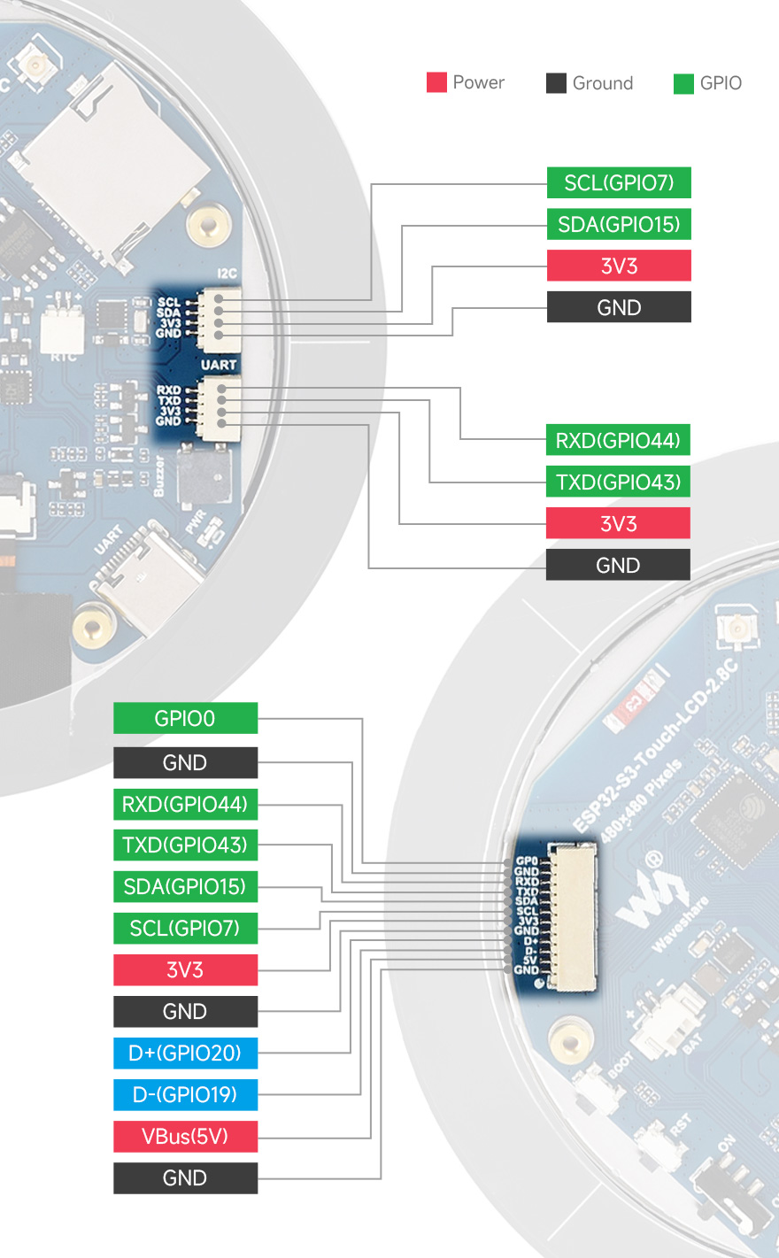
12-pin multifunction connector pinout:
| No. | Pin | Function | Description |
|---|---|---|---|
| 1 | GND | GND | Ground |
| 2 | VBus | 5 VDC | 5 VDC USB power |
| 3 | D- | USB differential (GPIO19) | USB differential line or usable as GPIO |
| 4 | D+ | USB differential (GPIO20) | USB differential line or usable as GPIO |
| 5 | GND | GND | Ground |
| 6 | 3V3 | 3.3 VDC | 3.3 VDC power output |
| 7 | SCL | SCL (GPIO7) | I2C clock line, cannot be used as a regular GPIO |
| 8 | SDA | SDA (GPIO15) | I2C data line, cannot be used as a regular GPIO |
| 9 | TXD | TXD (GPIO43) | UART transmit line or usable as GPIO |
| 10 | RXD | RXD (GPIO44) | UART receive line or usable as GPIO |
| 11 | NC | NC | Not connected |
| 12 | IO0 | GPIO0 | GPIO pin available for general use |
I2C connector pinout
| Pin | Function | Description |
|---|---|---|
| GND | GND | Ground |
| 3V3 | 3.3 VDC | 3.3 VDC power output |
| SCL | SCL (GPIO7) | I2C clock line, cannot be used as a regular GPIO |
| SDA | SDA (GPIO15) | I2C data line, cannot be used as a regular GPIO |
UART connector pinout
| Pin | Function | Description |
|---|---|---|
| GND | GND | Ground |
| 3V3 | 3.3 VDC | 3.3 VDC power output |
| TXD | TXD (GPIO43) | UART transmit line or usable as GPIO |
| RXD | RXD (GPIO44) | UART receive line or usable as GPIO |
Layout:
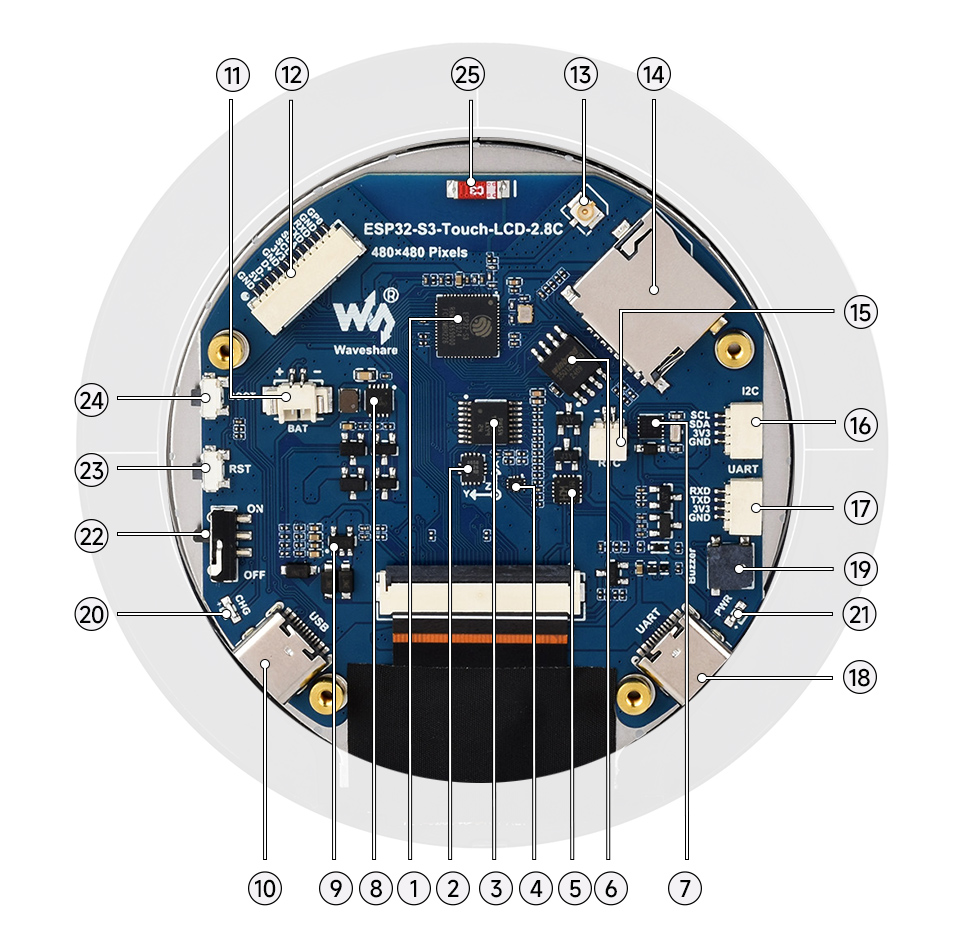
| No. | Description |
|---|---|
| 1 | ESP32-S3R8, dual-core processor with a clock speed of up to 240 MHz |
| 2 | QMI8658 orientation sensor, 6-axis IMU |
| 3 | TCA9554PWR, GPIO expander, used entirely internally and not brought out to connectors |
| 4 | FSUSB42UMX, UART selection circuit. The 4-pin UART connector is disabled when the Type-C UART port is connected |
| 5 | CH343P, USB-UART converter with automatic download circuit |
| 6 | 16 MB Flash memory |
| 7 | PCF85063, real-time clock circuit |
| 8 | Battery charging manager |
| 9 | ME6217C33M5G, LDO regulator with 800 mA maximum output current |
| 10 | USB Type-C connector |
| 11 | 2-pin MX1.25 battery connector for 3.7 V Li-Ion/Li-Po battery, with charging and discharging |
| 12 | 12-pin multifunction connector |
| 13 | IPEX Gen 1 connector, allows an external antenna by resoldering the antenna selection resistor |
| 14 | TF card slot (microSD) |
| 15 | Connector for the rechargeable RTC battery |
| 16 | I2C connector, connected to internal circuits. Supports only I2C peripherals and cannot be remapped |
| 17 | UART connector, available only when the USB-UART Type-C port is not connected |
| 18 | USB Type-C port for USB-UART, used for power, programming, and debugging |
| 19 | Buzzer |
| 20 | Charging indicator, on while charging and off when fully charged. Without a battery connected, the LED state may be undefined |
| 21 | Power indicator |
| 22 | Battery power control button |
| 23 | RESET button |
| 24 | BOOT button |
Main internal connections
| Signal | ESP32-S3 Pin |
|---|---|
| LCD_BL (backlight) | GPIO6 |
| LCD_SDA | GPIO1 |
| LCD_SCL | GPIO2 |
| LCD_RST | EXIO1 (via TCA9554) |
| LCD_CS | EXIO3 (via TCA9554) |
| PCLK | GPIO41 |
| DE | GPIO40 |
| VSYNC | GPIO39 |
| HSYNC | GPIO38 |
| TP_SDA | GPIO15 |
| TP_SCL | GPIO7 |
| TP_INT | GPIO16 |
| TP_RST | EXIO2 (via TCA9554) |
| TF Card MISO | GPIO42 |
| TF Card MOSI | GPIO1 |
| TF Card SCLK | GPIO2 |
| TF Card CS | EXIO4 (via TCA9554) |
| QMI8658 SCL / SDA | GPIO7 / GPIO15 |
| PCF85063 SCL / SDA | GPIO7 / GPIO15 |
| Buzzer | EXIO8 (via TCA9554) |
| Battery voltage measurement | GPIO4 |
Usage:
Connect the board to a computer using a USB Type-C cable. For programming and debugging, use the port labeled UART, which goes through the CH343P converter.
Install the CH343 driver for Windows or macOS, then check the COM port assigned in Device Manager.
In Arduino IDE, install ESP32 board support and select an ESP32-S3 model, then configure 16MB Flash and 8MB PSRAM (OPI PSRAM).
Insert a FAT32-formatted microSD card if you want to test the TF slot or load graphical resources.
Upload a simple example for verification, then move on to the LVGL demos provided by the manufacturer for full peripheral testing.
For the graphical interface, use the LVGL library together with the ST7701 driver for the display and GT911 for touch. The 8MB PSRAM allows smooth operation of graphical buffers.
If uploading fails, hold down the BOOT button, briefly press RESET, release RESET, then BOOT to enter programming mode manually.
For standalone power, connect a 3.7V Li-Ion or Li-Po battery to the MX1.25 connector and use the battery power control button. The battery voltage can be read on GPIO4.
To keep time after disconnecting the main power supply, connect a rechargeable battery to the dedicated RTC connector; otherwise, the clock resets at every startup.
If you need better radio coverage, mount an external antenna on the IPEX connector and reposition the antenna selection resistor.
Dimensions diagram:
.jpg)
Package contents:
1 x ESP32-S3-Touch-LCD-2.8C development board
1 x 12-pin SH1.0 cable, approximately 100 mm
2 x 4-pin SH1.0 cable, approximately 100 mm
Official documentation: https://www.waveshare.com/wiki/ESP32-S3-Touch-LCD-2.8C
- Microcontroller
- ESP32-S3
- Wireless connectivity
- WiFi + Bluetooth
- Screen size
- 2.8 inch
- Screen resolution
- 480x480
- Display type
- IPS
- Touchscreen
- Capacitiv
Produs destinat utilizarii in proiecte electronice, automatizari, prototipare, educatie si cercetare.
Produsul trebuie utilizat numai conform specificatiilor tehnice mentionate in descriere si/sau in documentatia produsului.
Avertismente generale de siguranta:
Nu utilizati produsul la tensiuni, curenti sau temperaturi peste valorile specificate.
Montajul si conectarea trebuie realizate de persoane cu cunostinte tehnice minime in domeniul electric/electronic.
Evitati scurtcircuitele, inversarea polaritatii si conectarea gresita a alimentarii.
Nu lasati produsul alimentat nesupravegheat in timpul testelor.
Produsul nu este jucarie si nu este destinat copiilor.
Pentru modulele electronice, se recomanda utilizarea in carcase, panouri sau montaje protejate, dupa caz.
Identificare produs:
Denumirea produsului, codul/SKU-ul si caracteristicile tehnice sunt mentionate in pagina produsului si/sau pe eticheta ambalajului.
Producator / Importator / Distribuitor:
Sigmanortec S.R.L.
Calea Bucuresti nr. 9, Targu Jiu, Gorj, Romania
E-mail: [email protected]
Website: www.sigmanortec.ro
Persoana responsabila in UE:
Sigmanortec S.R.L.
Calea Bucuresti nr. 9, Targu Jiu, Gorj, Romania
E-mail: [email protected]
Documentatie si siguranta:
Pentru informatii suplimentare, fise tehnice, declaratii de conformitate sau instructiuni, ne puteti contacta la [email protected].