

Product images are for informational purposes only and may vary slightly depending on the batch and supplier. Product specifications and prices may be subject to change without notice. We do our best to provide accurate and complete product specifications, but they may not be completely accurate. If you encounter any such situation, please let us know.
The product is intended for specialists and requires qualified and authorized personnel. The product does not include assembly/use instructions . Putting the product into operation by unqualified persons leads to the loss of the warranty according to the Terms and Conditions on the site.
The specified technical parameters (current, power, etc.) represent maximum allowable values under ideal operating conditions. For safe use and optimal lifespan, it is recommended to operate the product continuously at no more than 50% of the specified maximum values.
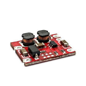
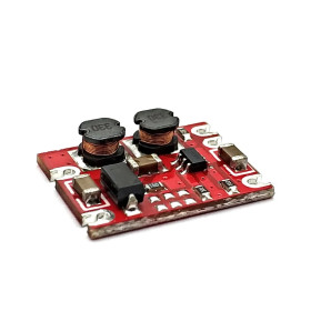
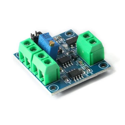
Voltage converter module: 0-5V and 0-10V to 0-100% PWM, 50 kHz
The module converts an analog voltage of 0-5V or 0-10V into a PWM signal with a duty cycle of 0-100%, based on an embedded microcontroller circuit. The input range is selected through a jumper mounted on the back of the board, and a potentiometer allows fine calibration of accuracy. It operates at a frequency of approximately 50 kHz, with an error of 1-3%, making it suitable for motor control, interfacing with PLCs, frequency converters, and modules such as Arduino, ESP32, or STM32.
Shipping by Thursday 22 October
Buying this product earns you 0.16 € in loyalty points.

International fast shipping within EU. Free Shipping for orders above 100 EUR in most EU countries.

We ship from our stock within 24H

You earn points with every order, worth 5%.
The module converts an analog voltage of 0 - 5 V or 0 - 10 V into a PWM signal with a duty cycle adjustable between 0% and 100%, depending on the level of the input voltage applied. It is useful where there is a need to convert an analog reference of 0 - 10 V, coming from a potentiometer, a PLC, or a frequency converter, into a PWM signal compatible with motor drivers, MOSFETs, or microcontrollers that accept only digital inputs.
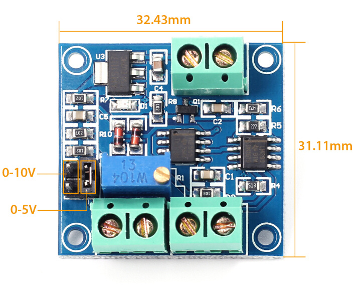
The conversion is performed by a circuit with an embedded microcontroller (MCU), which generates at the output a PWM signal with 5 V amplitude and a frequency of approximately 50 kHz, with a conversion error of 1% - 3%. The input range is selected by a shorting jumper mounted on the back of the board, which selects between 0 - 5 V and 0 - 10 V, the module being delivered from the factory in the 0 - 5 V position. A potentiometer mounted on the front of the board allows fine calibration of the conversion accuracy.
Among the main features are the three screw connectors for power supply, input voltage, and PWM output signal, the input range selection jumper, and the calibration potentiometer. The module is powered in the 7 - 12 VDC range through the VCC and GND pins, respecting the polarity indicated on the board.
Through the PWM output, the module is compatible with Arduino, ESP32, STM32, and other development boards that can read a PWM signal through a digital pin, and through the 0 - 10 V input it can be directly connected to the analog outputs of PLCs and frequency converters (VFDs) used in industrial automation.
Specifications:
Supply voltage: 7 - 12 VDC
Accepted voltage on VCC: 5 - 12 VDC
Function: Analog voltage to PWM signal converter
Technology: Embedded microcontroller (MCU) circuit
Input voltage range: 0 - 5 V or 0 - 10 V, selectable by jumper
Output range: PWM with duty cycle 0% - 100%
PWM signal amplitude: 5 V
PWM frequency: approximately 50 kHz
Conversion error: 1% - 3%
Operating temperature: -25 °C - 85 °C
Accuracy adjustment: Calibration potentiometer
Input range selection: Jumper on the back of the board, default set to 0 - 5 V
Applications: Motor control, interfacing with PLC and VFD, generating PWM signal from analog reference
Dimensions: 31 x 32mm
Pinout:
| Connector | Pin | Function |
|---|---|---|
| Power connector | VCC | Module power supply |
| Power connector | GND | Power ground |
| Voltage input connector | VIN | Measured voltage input, 0 - 5 V or 0 - 10 V |
| Voltage input connector | GND | Input signal ground |
| PWM output connector | PWM | PWM signal output, duty cycle 0% - 100% |
| PWM output connector | GND | Output signal ground |
| Jumper position | VIN voltage range |
|---|---|
| Default, from factory | 0 - 5 V |
| Moved to second position | 0 - 10 V |
Usage:
Connect the power supply to the VCC and GND pins of the power connector, in the 7 - 12 VDC range, respecting the polarity indicated on the board.
Do not reverse the power wires, to avoid damaging the components on the board.
Connect the voltage to be measured to the VIN and GND pins of the input connector, in the 0 - 5 V or 0 - 10 V range.
Check the position of the jumper on the back of the board and set it to the voltage range used, knowing that the module is delivered by default in the 0 - 5 V position.
Take the signal from the PWM and GND pins of the output connector, a signal with 5 V amplitude and a frequency of approximately 50 kHz.
Change the voltage applied to VIN to adjust the duty cycle of the PWM signal between 0% and 100%.
For calibration, apply a known reference voltage to VIN and adjust the potentiometer on the board until the measured duty cycle matches the expected value.
To read the signal with Arduino, ESP32, or STM32, connect the PWM output to a digital pin and use a pulse measurement function, with a common ground between modules.
For use with PLCs or frequency converters, connect their 0 - 10 V analog output to the VIN input, respecting the module’s voltage limits.
For stable results, use a clean, noise-free power supply and short cables between the voltage source and the VIN connector.
- Input Voltage
- 0-10 V
- Input Voltage Type
- “DC” in Romanian can mean **“de ce”**, which translates to **“why”** in English.
- Control method
- PWM
- PWM signal frequency
- 50 kHz
- Duty cycle
- 0 - 100 %
Produs destinat utilizarii in proiecte electronice, automatizari, prototipare, educatie si cercetare.
Produsul trebuie utilizat numai conform specificatiilor tehnice mentionate in descriere si/sau in documentatia produsului.
Avertismente generale de siguranta:
Nu utilizati produsul la tensiuni, curenti sau temperaturi peste valorile specificate.
Montajul si conectarea trebuie realizate de persoane cu cunostinte tehnice minime in domeniul electric/electronic.
Evitati scurtcircuitele, inversarea polaritatii si conectarea gresita a alimentarii.
Nu lasati produsul alimentat nesupravegheat in timpul testelor.
Produsul nu este jucarie si nu este destinat copiilor.
Pentru modulele electronice, se recomanda utilizarea in carcase, panouri sau montaje protejate, dupa caz.
Identificare produs:
Denumirea produsului, codul/SKU-ul si caracteristicile tehnice sunt mentionate in pagina produsului si/sau pe eticheta ambalajului.
Producator / Importator / Distribuitor:
Sigmanortec S.R.L.
Calea Bucuresti nr. 9, Targu Jiu, Gorj, Romania
E-mail: [email protected]
Website: www.sigmanortec.ro
Persoana responsabila in UE:
Sigmanortec S.R.L.
Calea Bucuresti nr. 9, Targu Jiu, Gorj, Romania
E-mail: [email protected]
Documentatie si siguranta:
Pentru informatii suplimentare, fise tehnice, declaratii de conformitate sau instructiuni, ne puteti contacta la [email protected].
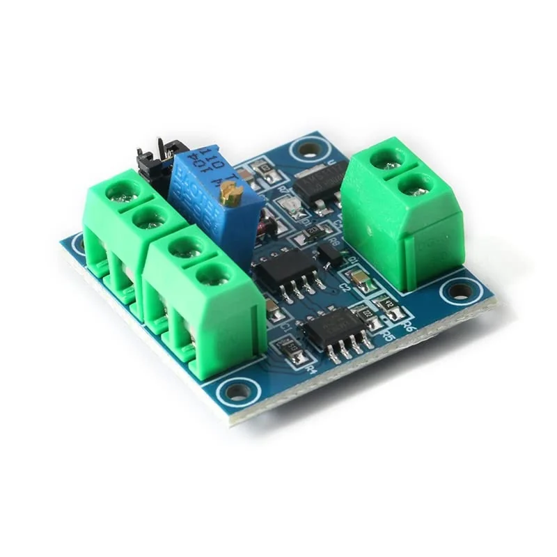
The Voltage to PWM converter module is a small-sized board that converts an analog voltage of 0 - 5 V or 0 - 10 V into a PWM signal with a duty cycle adjustable between 0% and 100%. It is a standalone module, with its own conversion circuit, which works on its own once powered, without needing an external microcontroller or a program.
This tutorial shows how to set up the module as is, with a test voltage source at the input and a multimeter or an oscilloscope at the output, to see how the duty cycle of the PWM signal varies depending on the applied voltage.
How it works:
The circuit on the board measures the voltage applied at the VIN input and generates at the PWM output a square wave signal with a fixed amplitude of 5 V and a frequency of approximately 50 kHz, where the duty cycle is proportional to the input voltage.
The relationship is linear, Duty cycle percentage equals Input voltage divided by the Maximum voltage of the selected range, multiplied by 100. For example, if the jumper is in the 0 - 10 V position and you apply 5 V at VIN, the output duty cycle will be approximately 50%, and if you apply 10 V, the duty cycle will be approximately 100%.
The typical conversion error is 1% - 3%, and the potentiometer on the front of the board allows fine-tuning of this accuracy, by comparing the applied voltage with the duty cycle measured at a certain reference voltage.
What you need:
- 1 x Voltage to PWM converter module 0-5V and 0-10V to 0-100%, 50 kHz
- 1 x 12V, 2A Power Supply
- 1 x Linear Potentiometer Module, 10k, 3.3-5V
- 1 x Q1 Digital Multimeter, True-RMS, NVC, temperature sensor, automatic
- 1 x Motor driver module, dual H-bridge, DRV8833, 1.5A
- 1 x Battery Holder, 4AA, with Wires
Wiring:
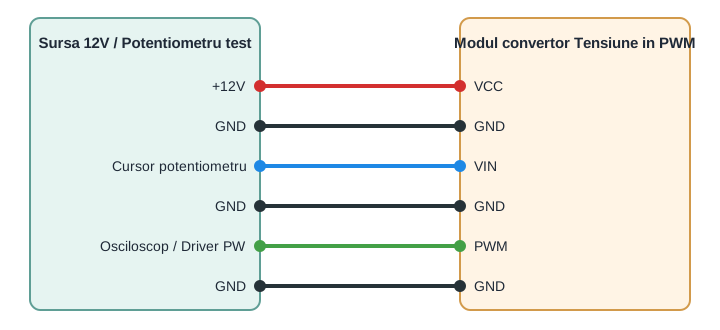
The module is powered in the 7 - 12 VDC range through the VCC and GND pins, while the test voltage is applied on the VIN and GND pins of the input connector, respecting the range selected via the jumper.
| Product pin | Connects to | Role |
|---|---|---|
| VCC | 12 VDC Source, positive terminal | Module power supply |
| GND (power) | 12 VDC Source, negative terminal | Power ground |
| VIN | Test potentiometer wiper | Voltage to be measured, 0 - 5 V or 0 - 10 V |
| GND (input) | Common ground with the source | Input signal ground |
| PWM | Oscilloscope or multimeter input | PWM signal output, 0% - 100% |
| GND (output) | Common ground with the source | Output signal ground |
Configuration:
Before powering the module, check the position of the input range selection jumper, knowing that the module ships from the factory in the 0 - 5 V position.
If your test source provides voltages between 0 and 10 V, move the jumper to the second position for the 0 - 10 V range, otherwise voltages above 5 V will saturate the output at 100%.
| Jumper position | VIN voltage range |
|---|---|
| Default, from factory | 0 - 5 V |
| Moved to second position | 0 - 10 V |
For calibration, power up the module, apply a known reference voltage at VIN, for example exactly half of the chosen scale endpoint, and measure the output duty cycle with an oscilloscope or with the pulse measurement function of a multimeter.
If the measured duty cycle does not match the expected value, gently turn the potentiometer on the board until the measured value gets close to the calculated one, then repeat the check at two other points in the range, for example near 0% and near 100%, to confirm linearity.
The settings remain mechanically stored through the position of the potentiometer and the jumper, without needing reprogramming at every power-up.
Example of use:
A typical use is controlling the speed of a DC motor through a MOSFET driver that accepts a PWM input. Connect a 10 k linear potentiometer between a 10 V source and ground, with the wiper at VIN, set the jumper to the 0 - 10 V position, then connect the module's PWM output to the control input of the motor driver.
By turning the potentiometer from one end to the other, the duty cycle goes from approximately 0% to approximately 100%, and the motor speed increases proportionally, from stopped up to the maximum speed allowed by the driver and by the motor's power supply.
Common issues:
The PWM output stays at 0% or at 100% at all times, regardless of the voltage applied at VIN, usually because the jumper is in the wrong position relative to the actual range of the test source, for example jumper on 0 - 5 V while applying 0 - 10 V.
The measured duty cycle differs noticeably from the calculated value, the cause usually being a decalibrated potentiometer on the board or a missing common ground between the test source and the module.
The module seems to not respond at all, first check the power supply on VCC and GND with a multimeter, in the 7 - 12 VDC range, and check the polarity, since reversed power can stop the circuit from working.
The PWM signal read with a regular multimeter shows unstable values, this is normal because many multimeters cannot correctly measure a 50 kHz signal, requiring an oscilloscope or a multimeter with a dedicated duty cycle measurement function.
The motor or the load controlled through the driver does not start at all, check whether the MOSFET driver uses the same 5 V level for the PWM signal and whether the driver's ground is connected to the module's ground.
Limitations and tips:
The module accepts a single conversion channel, with a typical error of 1% - 3%, sufficient for motor control and for interfacing with industrial equipment, but not for precision laboratory measurements.
The fixed frequency of approximately 50 kHz cannot be changed by the user, so the module is suitable for drivers and microcontrollers that accept this frequency on the PWM control input.
For stable results, use a clean, noise-free power supply, short cables between the voltage source and VIN, and a well-made common ground between the module, the test source and the controlled equipment.
Once validated with a test source, the module can be permanently integrated into a setup with a potentiometer, with the analog output of a PLC or of a frequency converter, or it can be read directly by a microcontroller such as Arduino, ESP32 or STM32 through a digital pin.