
Product images are for informational purposes only and may vary slightly depending on the batch and supplier. Product specifications and prices may be subject to change without notice. We do our best to provide accurate and complete product specifications, but they may not be completely accurate. If you encounter any such situation, please let us know.
The product is intended for specialists and requires qualified and authorized personnel. The product does not include assembly/use instructions . Putting the product into operation by unqualified persons leads to the loss of the warranty according to the Terms and Conditions on the site.
The specified technical parameters (current, power, etc.) represent maximum allowable values under ideal operating conditions. For safe use and optimal lifespan, it is recommended to operate the product continuously at no more than 50% of the specified maximum values.
Resistor 1/4W, metal film, 0.25W, 1%, axial
Metal film resistor, ideal for current limiting and voltage dividers in electronic circuits, offers good long-term stability and low noise. Power 0.25W, 1/4W format, 1% tolerance for measurements and precise projects, available in different values for quick adaptation to any application.
Buying this product earns you 0.01 RON in loyalty points.

International fast shipping within EU. Free Shipping for orders above 100 EUR in most EU countries.

We ship from our stock within 24H

You earn points with every order, worth 5%.
The 1/4 W metal film resistor is a passive component with two axial terminals, used for limiting current, dividing voltage and setting voltage levels in an electronic circuit. The 1% tolerance makes it suitable for circuits where the value must be close to the marked one, such as voltage dividers, RC filters, pull-up and pull-down resistors and series resistors for LEDs.
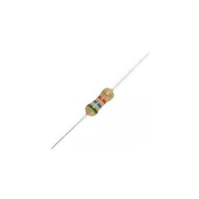
The part has a rated power of 0.25 W and a tolerance of 1%, and the resistance value is read from the colour bands on the body. The resistor is available in different values, so the value of each part should be checked using the colour code or with a multimeter. The axial terminals, about 0.6 mm in diameter, fit the standard holes of test boards and breadboards.
The main features include the cylindrical body with colour bands marking the value, the two axial terminals for through-hole (THT) mounting, and the metal film construction with no polarity, so the resistor can be mounted in either direction.
Specifications:
Type: Metal film resistor
Model: 1/4W
Rated power: 0.25 W
Tolerance: 1%
Value: Different values, marked by colour bands
Mounting: THT, axial terminals
Terminal diameter: approximately 0.6 mm
Dimensions: 6.3 x 2.4 mm
Usage:
Read the resistor value from the colour bands, holding the part with the tolerance band on the right, then confirm the value with a multimeter on the ohms range, with the resistor removed from the circuit.
Do not touch both terminals with your fingers at the same time during the measurement, because the resistance of the body will change the result.
Calculate the required value using Ohm's law. For an LED, use the formula R = (Valim - Vf) / I, where Vf is the forward voltage of the LED and I is the desired current.
Check the dissipated power with the formula P = I x I x R and keep it at no more than half of the rated power, that is approximately 125 mW, for a long service life.
Bend the terminals to the distance between the holes, without forcing the resistor body, then insert the part into the test board or breadboard.
For soldered mounting, solder the terminals quickly and let the part cool, so as not to affect the resistive layer.
Do not exceed the rated power of 0.25 W. An overheated resistor changes its value and can be damaged.
The resistor has no polarity, so it does not matter which terminal goes to plus and which to minus.
- Dimensions
- 6.3 x 2.4 mm
- Model
- 1/4 W
- Type
- Metal film resistor
- Power
- 0.25 W
- Mounting
- THT, axial leads
- Tolerance
- 1%
Produs destinat utilizarii in proiecte electronice, automatizari, prototipare, educatie si cercetare.
Produsul trebuie utilizat numai conform specificatiilor tehnice mentionate in descriere si/sau in documentatia produsului.
Avertismente generale de siguranta:
Nu utilizati produsul la tensiuni, curenti sau temperaturi peste valorile specificate.
Montajul si conectarea trebuie realizate de persoane cu cunostinte tehnice minime in domeniul electric/electronic.
Evitati scurtcircuitele, inversarea polaritatii si conectarea gresita a alimentarii.
Nu lasati produsul alimentat nesupravegheat in timpul testelor.
Produsul nu este jucarie si nu este destinat copiilor.
Pentru modulele electronice, se recomanda utilizarea in carcase, panouri sau montaje protejate, dupa caz.
Identificare produs:
Denumirea produsului, codul/SKU-ul si caracteristicile tehnice sunt mentionate in pagina produsului si/sau pe eticheta ambalajului.
Producator / Importator / Distribuitor:
Sigmanortec S.R.L.
Calea Bucuresti nr. 9, Targu Jiu, Gorj, Romania
E-mail: [email protected]
Website: www.sigmanortec.ro
Persoana responsabila in UE:
Sigmanortec S.R.L.
Calea Bucuresti nr. 9, Targu Jiu, Gorj, Romania
E-mail: [email protected]
Documentatie si siguranta:
Pentru informatii suplimentare, fise tehnice, declaratii de conformitate sau instructiuni, ne puteti contacta la [email protected].
Reviews (16) - Review moderation

Aceste rezistoare sunt utile și precise.
aaaa
Bun
Bun
Bun
This tutorial uses only a simple circuit, made up of a 9 V battery, a 1/4 W metal film resistor and a 5 mm red LED. No program is needed, and the circuit can be built on a breadboard or directly with wires.
The 1/4 W resistor with 1% tolerance is used in projects for limiting the current through LEDs, in voltage dividers, in pull-up and pull-down resistors and in RC filters. Here we put it to work in its most common role, as a series resistor for an LED.

How it works:
The resistor opposes the flow of electric current. The relationship between the voltage across its terminals and the current flowing through it is Ohm's law: U = I x R.
An LED has an almost constant voltage across its terminals when it conducts, about 2.0 V for a 5 mm red LED. If it were connected directly to the battery, the current would rise uncontrolled and the LED would be destroyed. The resistor takes up the voltage difference and sets the current.
The value is calculated with the formula R = (Vsupply - Vf) / I. For a 9 V battery, a red LED with a Vf of about 2.0 V and a desired current of about 7 mA, we get R = (9 - 2.0) / 0.007 = 1000 ohms, i.e. 1 kohm. This is a standard value, and the current stays well below the usual limit of 20 mA for 5 mm LEDs. The exact limit should be checked in the datasheet of the LED used.
The resistor converts energy into heat, so the dissipated power must also be checked: P = I x I x R = 0.007 x 0.007 x 1000, i.e. about 49 mW. This value is well below the rated power of 0.25 W and below half of it (125 mW), the recommended limit for a long service life.
A tolerance of 1% means the actual value deviates by at most 1% from the marked one. For a 1 kohm resistor, the actual value lies between 990 and 1010 ohms. The resistor has no polarity and works the same regardless of the direction in which it is mounted.
Connection:
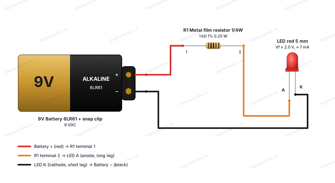
The circuit has three elements: the 9 V battery (6LR61) with snap connector, the resistor R1 of 1 kohm and a 5 mm red LED. There are no logic levels or separate supplies, and the current in the circuit is about 7 mA. On the snap connector, the red wire is positive and the black wire is negative.
| Product pin | Connect to | Role |
|---|---|---|
| R1 terminal 1 | Positive of the 9 V battery (red wire of the snap connector) | Power supply |
| R1 terminal 2 | LED anode (A, the longer leg) | Signal, current limited to the LED |
The LED cathode (K, the shorter leg, next to the flat side of the rim) is connected to the battery negative, that is, to the black wire of the snap connector. If you mount the LED in reverse, it will not light up, but it will not be damaged at this voltage.
Configuration:
The resistor has no buttons, potentiometers or jumpers, so there is nothing to adjust. The only choice is the value suitable for the supply voltage and for the LED. The value remains fixed for the entire life of the part, as long as the rated power is not exceeded.
Step 1. Hold the resistor so that the tolerance band (brown for 1%) is on the right, usually further away from the other bands. Reading is done from left to right.
Step 2. For the 5-band code, the first three bands are the digits, the fourth is the multiplier, and the fifth is the tolerance. The digits are: black 0, brown 1, red 2, orange 3, yellow 4, green 5, blue 6, violet 7, grey 8, white 9.
Step 3. Confirm the value with a multimeter on the ohms range, with the resistor removed from the circuit, holding the terminals only with the probes.
| Value | Bands (5 bands, 1% tolerance) |
|---|---|
| 220 ohms | Red, red, black, black, brown |
| 1 kohm | Brown, black, black, brown, brown |
| 10 kohms | Brown, black, black, red, brown |
Step 4. Choose the value according to the supply voltage. The values in the table are for a red LED.
| Supply voltage | Resistor for red LED |
|---|---|
| 3.3 V | 68 - 100 ohms |
| 5 V | 150 - 330 ohms |
| 9 V | 1 kohm |
| 12 V | 1.5 kohms |
Usage example:
The goal is to light a 5 mm red LED from a 9 V battery, with a current of about 7 mA. Choose a 1 kohm resistor, that is brown, black, black, brown, brown, and check it with the multimeter. The measured value must be between 990 and 1010 ohms.
Disconnect the battery from the snap connector. Insert the resistor R1 between the positive of the battery and the LED anode, then connect the LED cathode to the negative of the battery. Connect the battery to the snap connector.
The LED should light up immediately. With a multimeter in series, on the current range, you will read about 7 mA. The voltage across the resistor is about 7 V, and the dissipated power is about 49 mW, so the resistor stays cool to the touch.
For a brighter LED, switch to a 680 ohm resistor. The current rises to about 10 mA, and the dissipated power to about 70 mW, both within safe limits for a 5 mm LED and for this resistor.
Common problems:
The LED does not light up. The most common cause is the LED being mounted in reverse or a discharged battery. Check that the long leg of the LED goes toward the resistor and the short one toward the battery negative, then measure the battery voltage.
The LED lights up very weakly. The resistor probably has a much higher value than intended, for example due to a misread colour code. Measure the value with the multimeter and replace the resistor with the correct one.
The LED lights up very strongly, gets hot or burns out. The resistor has a value that is too low or is missing from the circuit. Disconnect the battery immediately, check the resistor value and recalculate the current with the formula R = (Vsupply - Vf) / I.
The multimeter shows a value different from the marked one. If you held both terminals with your fingers or the resistor stayed in the circuit, the reading is distorted. Remove the part from the circuit and touch the terminals only with the probes. Also check that the value falls within the 1% tolerance.
The resistor gets too hot. The dissipated power is too close to the rated power. Recalculate with P = I x I x R and choose a higher value or a resistor with a higher rated power.
Limitations and tips:
The rated power is 0.25 W, and for long-term operation it is recommended not to exceed about 125 mW. A tolerance of 1% means the actual value may differ by at most 1% from the marked one, and the value may change slightly with temperature and with heating of the part.
When soldering, do not heat the terminals too much close to the body, and when mounting, do not bend the terminal right at the base of the body.
With the same type of resistor you can go on to build voltage dividers, low-pass or high-pass RC filters, pull-up and pull-down resistors and current limiting circuits for several LEDs, each with its own resistor.