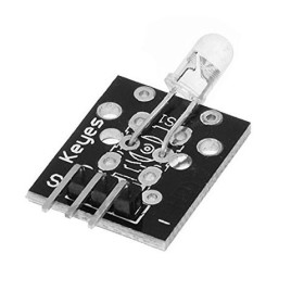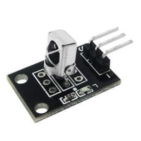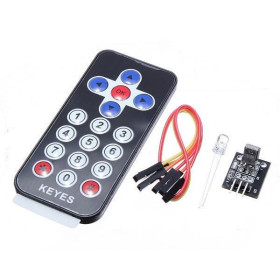

Product images are for informational purposes only and may vary slightly depending on the batch and supplier. Product specifications and prices may be subject to change without notice. We do our best to provide accurate and complete product specifications, but they may not be completely accurate. If you encounter any such situation, please let us know.
The product is intended for specialists and requires qualified and authorized personnel. The product does not include assembly/use instructions . Putting the product into operation by unqualified persons leads to the loss of the warranty according to the Terms and Conditions on the site.
The specified technical parameters (current, power, etc.) represent maximum allowable values under ideal operating conditions. For safe use and optimal lifespan, it is recommended to operate the product continuously at no more than 50% of the specified maximum values.
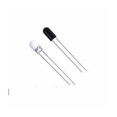
IR LED Emitter and Receiver Pair, 5mm, 940nm, Transparent and Black Body
IR LED emitter and receiver pair, 5mm, ideal for optical barriers, presence detection and contactless control. Provides infrared emission and reception for automation systems and electronic projects, standard 5mm format easy to mount, fast response and simple integration on PCBs, suitable for DIY or industrial applications.
Shipping by Wednesday 11 November
Buying this product earns you 0.08 RON in loyalty points.

International fast shipping within EU. Free Shipping for orders above 100 EUR in most EU countries.

We ship from our stock within 24H

You earn points with every order, worth 5%.
The 5 mm infrared LED pair contains two separate components: an IR emitter with a transparent body and a receiver with a black body, which blocks visible light and lets infrared light pass. The emitter produces invisible light with a wavelength of 940 nm, and the receiver is a photodiode for the same wavelength, whose current increases with the intensity of the received IR light. The pair is suitable for optical barriers, reflective object sensors, parts counters, line detectors for robots and simple proximity sensors.
The receiver measures the intensity of infrared light and does not decode remote control codes. The emitter typically works at a forward current of 20 mA, with a forward voltage of 1.3 - 1.5 V, so it needs a series current-limiting resistor. The receiver is connected in reverse bias, and its current is converted into voltage with a resistor, for example 10 kOhm, and this voltage can then be read with an analog input or with a comparator.
The main features include a wavelength of 940 nm, a body diameter of 5 mm, a transparent-body emitter, a black-body receiver with a filter for visible light, two terminals for each component and through-hole mounting on a breadboard or PCB. The components have no power supply of their own: the emitter is powered through a current-limiting resistor, for example 220 ohms at 5 V, and the receiver is reverse biased from the same 5 V supply.
Specifications:
Emitter forward voltage: 1.3 - 1.5 V
Emitter forward current: 20 mA (typical)
Wavelength: 940 nm
Emitter type: IR LED, transparent body
Receiver type: IR photodiode, black body
Number of terminals: 2 for each component
Mounting: Through-hole (THT)
Dimensions: 5 mm diameter
Pinout:
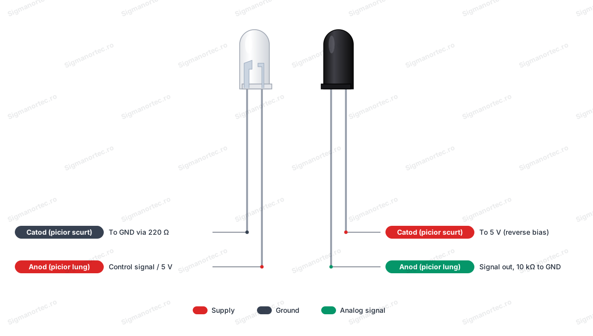
| Connector | Pin | Function |
|---|---|---|
| IR emitter (transparent body) | Anode (long leg) | Connect to the positive of the control signal or to 5 V |
| IR emitter (transparent body) | Cathode (short leg) | Connect to GND through a current-limiting resistor, for example 220 ohms |
| IR receiver (black body) | Cathode (short leg) | Connect to 5 V for reverse bias |
| IR receiver (black body) | Anode (long leg) | Measurement point, connect to the read input and to a 10 kOhm resistor to GND |
Usage:
Identify the two components by their body: the emitter has a transparent body, and the receiver has a black body. On both components the long leg is the anode, and the short leg is the cathode, also marked by the flat edge of the body.
Never connect the emitter directly to 5 V or to a digital output without a current-limiting resistor, because an uncontrolled current will destroy the diode.
Connect the emitter anode to the control source, and its cathode to GND through a 220 ohm resistor. At 5 V the current is approximately 17 mA, below the typical value of 20 mA.
Connect the receiver cathode to 5 V so that the photodiode works in reverse bias, and its anode to the read input and to a 10 kOhm resistor to GND. The voltage across the resistor increases with the received IR light.
For reflective detection, place the emitter and receiver side by side, facing the same direction, 5 - 10 mm apart. An object in front of them reflects the emitter light toward the receiver and raises the read voltage.
For an optical barrier, place the two components face to face, and an object passing between them reduces the read voltage.
For stable results, measure the voltage once with the emitter off and once with the emitter on, and use the difference, so that ambient IR light from the sun or incandescent bulbs does not affect the result. Shield the receiver from direct sunlight.
To check the emitter, look at it through a phone camera: the infrared light appears as a faint violet light.
- Type
- Infrared LED, clear body
- Number of pins
- 2 pe fiecare componenta
- Mounting
- Through-hole (THT)
- Diameter
- 5 mm
- Sensor
- IR photodiode, black body
- Wavelength
- 940 nm
Produs destinat utilizarii in proiecte electronice, automatizari, prototipare, educatie si cercetare.
Produsul trebuie utilizat numai conform specificatiilor tehnice mentionate in descriere si/sau in documentatia produsului.
Avertismente generale de siguranta:
Nu utilizati produsul la tensiuni, curenti sau temperaturi peste valorile specificate.
Montajul si conectarea trebuie realizate de persoane cu cunostinte tehnice minime in domeniul electric/electronic.
Evitati scurtcircuitele, inversarea polaritatii si conectarea gresita a alimentarii.
Nu lasati produsul alimentat nesupravegheat in timpul testelor.
Produsul nu este jucarie si nu este destinat copiilor.
Pentru modulele electronice, se recomanda utilizarea in carcase, panouri sau montaje protejate, dupa caz.
Identificare produs:
Denumirea produsului, codul/SKU-ul si caracteristicile tehnice sunt mentionate in pagina produsului si/sau pe eticheta ambalajului.
Producator / Importator / Distribuitor:
Sigmanortec S.R.L.
Calea Bucuresti nr. 9, Targu Jiu, Gorj, Romania
E-mail: [email protected]
Website: www.sigmanortec.ro
Persoana responsabila in UE:
Sigmanortec S.R.L.
Calea Bucuresti nr. 9, Targu Jiu, Gorj, Romania
E-mail: [email protected]
Documentatie si siguranta:
Pentru informatii suplimentare, fise tehnice, declaratii de conformitate sau instructiuni, ne puteti contacta la [email protected].
Reviews (3) - Review moderation

Dupa masura e simplu 5v DC. La 4.6V devine puternic, si la 5v este cea luminos. Nu stiu daca se merge la constant 5V sau e prea mult. Masurati si voi.
Presupun ca ala alb e emitator, daca da, ce model ea Ca nu reusesc sa-l alimentez. Dan
Exact ce ami trebuia
/*
  IR emitter and receiver pair, raw reading test

  Board: Arduino Uno (Tools > Board > Arduino AVR Boards > Arduino Uno)
  Board package: Arduino AVR Boards (comes with the Arduino IDE)
  Libraries: none needed

  Wiring:
    D3  -> IR emitter anode (long leg)
    IR emitter cathode (short leg) -> 220 ohm resistor -> GND
    5V  -> IR receiver cathode (short leg)
    A0  -> IR receiver anode (long leg) and one end of a 10 kohm resistor
    10 kohm resistor other end -> GND
*/

const int EMITTER_PIN = 3;     // Drives the IR emitter
const int RECEIVER_PIN = A0;   // Reads the IR receiver

void setup() {
  Serial.begin(9600);                // Serial monitor speed
  pinMode(EMITTER_PIN, OUTPUT);      // Emitter pin is an output
  digitalWrite(EMITTER_PIN, LOW);    // Emitter starts off
}

void loop() {
  digitalWrite(EMITTER_PIN, LOW);    // Emitter off
  delay(5);
  int off = analogRead(RECEIVER_PIN);

  digitalWrite(EMITTER_PIN, HIGH);   // Emitter on
  delay(5);
  int on = analogRead(RECEIVER_PIN);

  digitalWrite(EMITTER_PIN, LOW);    // Emitter off again

  Serial.print("Emitter off: ");
  Serial.print(off);
  Serial.print("  Emitter on: ");
  Serial.print(on);
  Serial.print("  Difference: ");
  Serial.println(on - off);

  delay(500);                        // Wait between measurements
}
In this tutorial we put the pair of 5 mm IR LEDs into operation, made up of an infrared emitter with a transparent body and a receiver with a black body. The components have no controller of their own, so we use them together with a microcontroller. We work with an Arduino Uno R3, powered through the USB cable from the computer, because the board has everything we need: a digital output, an analog input and 5 V.
The pair is used for object sensors based on reflection, optical barriers, part counters, line detectors for robots and simple proximity sensors. The receiver only measures the intensity of the IR light, it does not decode remote control codes.

How it works:
The emitter is a diode that produces infrared light with a wavelength of 940 nm. The light is not visible to the naked eye, but a phone camera can show it as a faint violet light. The receiver is a photodiode for the same wavelength. It is connected in reverse bias, meaning the cathode is connected to 5 V. The more IR light it receives, the higher the current that flows through it.
The receiver current flows through a 10 kohm resistor towards GND, and the voltage drop across the resistor is read by the analog input A0. The relation is U = I x R. For example, a current of 10 uA produces 0.1 V across 10 kohm. The analog-to-digital converter of the Arduino Uno board has 10 bits, so it divides 5 V into 1024 steps of approximately 4.88 mV. Without IR light, the reading stays close to 0, and with strong light it rises towards 1023.
The emitter has a typical forward voltage of 1.3 - 1.5 V and a typical operating current of 20 mA. Without a resistor, the current would rise uncontrollably and would destroy the diode and the board pin. With a 220 ohm resistor we calculate: (5 V - 1.3 V) / 220 ohms, which is approximately 17 mA. The value stays below 20 mA, so both the diode and the D3 pin of the board are safe.
Ambient light also contains infrared, coming from the sun and from incandescent bulbs. For this reason the program reads A0 twice, once with the emitter off and once with the emitter on, and uses the difference. This way the light in the room is subtracted and only the light emitted by the LED and reflected by the object remains.
Connection:
Power the Arduino Uno board only through the USB cable. The circuit uses 5 V and 5 V logic, so no level converter is needed. Two resistors complete the circuit: R1 of 220 ohms for the emitter and R2 of 10 kohm for the receiver. On both diodes the long leg is the anode, and the short leg is the cathode. On the body, the flat side of the edge marks the cathode.
| Product pin | Connect to | Role |
|---|---|---|
| IR emitter (transparent body), anode (long leg) | Arduino Uno D3 | Drives the emitter. Pin D3 is marked with ~3 on the board. |
| IR emitter, cathode (short leg) | R1 resistor of 220 ohms, then GND | Limits the current to approximately 17 mA. |
| IR receiver (black body), cathode (short leg) | Arduino Uno 5V | Reverse bias of the photodiode. |
| IR receiver, anode (long leg) | Arduino Uno A0 and end 1 of the R2 resistor of 10 kohm | Measuring point. The voltage proportional to the IR light is read here. |
| R2 resistor of 10 kohm, end 2 | Arduino Uno GND | Converts the photodiode current into voltage. |
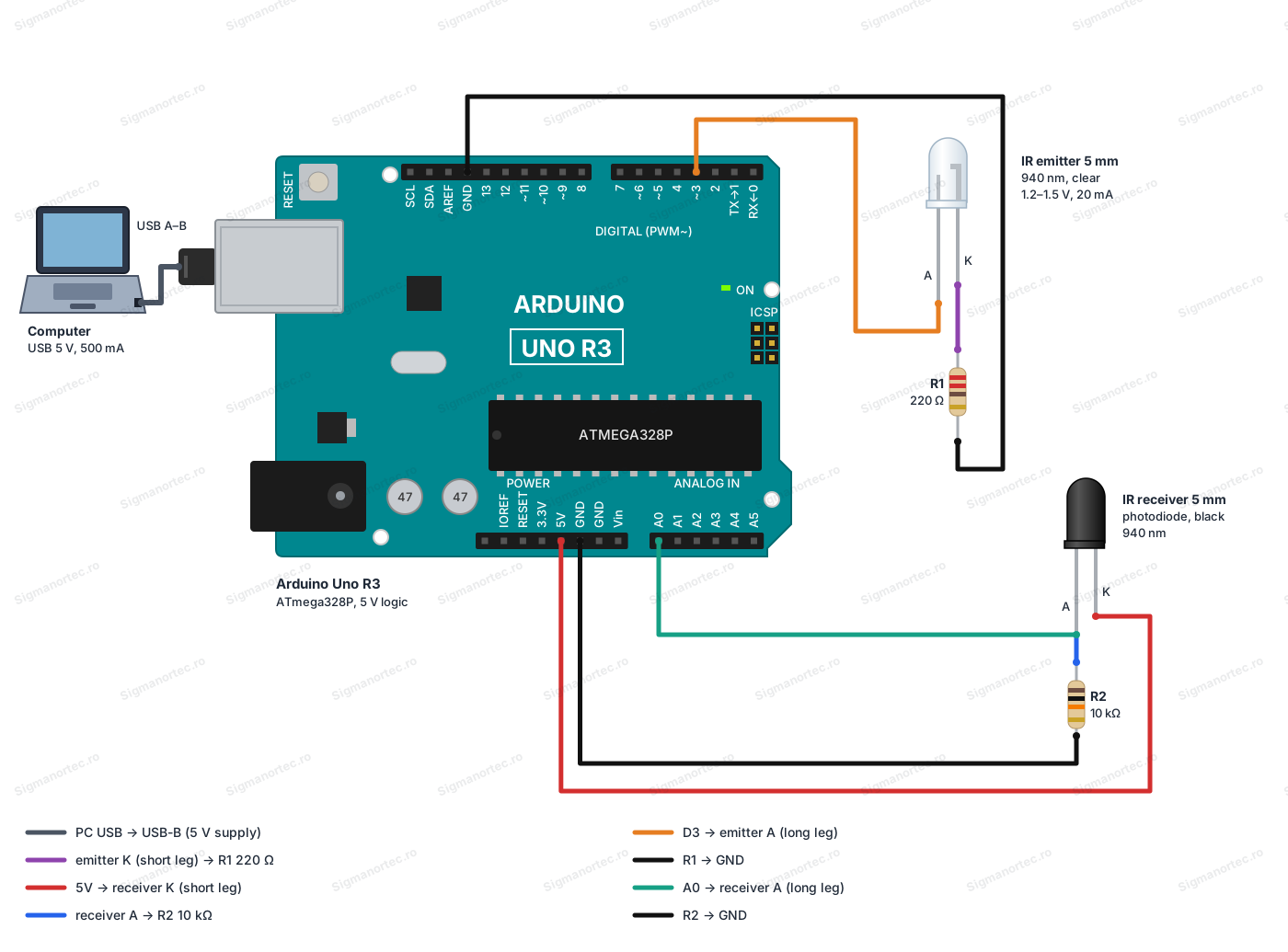
Never connect the emitter directly to 5 V or to D3 without the R1 resistor. If there is only one free GND pin on the breadboard, the two resistors can share the same ground line.
Orient the emitter and the receiver in the same direction, side by side, at a distance of 5 - 10 mm between them. In this position the receiver sees the light reflected by an object in front of them. For an optical barrier, place the two diodes facing each other, and an object passing between them will reduce the reading.
Board and libraries:
In the Arduino IDE select Tools > Board > Arduino AVR Boards > Arduino Uno. The Arduino AVR Boards package comes installed with the Arduino IDE, so no address needs to be added in File > Preferences.
The program only uses the basic Arduino functions (pinMode, digitalWrite, analogRead, delay and Serial), so no library needs to be installed.
The code:
The program measures the IR light with the emitter off and on, calculates the difference, decides whether an object reflects the light and displays the result on the serial monitor.
/*
  IR emitter and receiver pair, reflection and light barrier test
  Board: Arduino Uno (Tools > Board > Arduino AVR Boards > Arduino Uno)
  Board package: Arduino AVR Boards (comes with the Arduino IDE)
  Libraries: none, the program uses only the core Arduino functions
  Wiring:
    D3  -> IR emitter anode (long leg)
    IR emitter cathode (short leg) -> R1 220 ohm -> GND
    5V  -> IR receiver cathode (short leg)
    A0  -> IR receiver anode (long leg) and R2 10 kohm
    R2 10 kohm other end -> GND
*/
const int EMITTER_PIN = 3;         // Digital pin that drives the IR emitter
const int RECEIVER_PIN = A0;       // Analog pin that reads the IR receiver
const int SAMPLES = 8;             // Number of readings averaged per measurement
const int DETECT_THRESHOLD = 30;   // Minimum difference (ADC counts) to report an object
// Read the receiver several times and return the average value
int readAverage() {
  long sum = 0;
  for (int i = 0; i < SAMPLES; i++) {
    sum += analogRead(RECEIVER_PIN);  // One ADC reading, 0 to 1023
    delayMicroseconds(200);           // Short pause between readings
  }
  return (int)(sum / SAMPLES);
}
void setup() {
  Serial.begin(9600);                 // Start the serial monitor at 9600 baud
  pinMode(EMITTER_PIN, OUTPUT);       // The emitter pin is an output
  digitalWrite(EMITTER_PIN, LOW);     // Start with the emitter off
  Serial.println("IR pair test started");
}
void loop() {
  // Measure the ambient infrared light with the emitter off
  digitalWrite(EMITTER_PIN, LOW);
  delay(2);                           // Let the signal settle
  int ambient = readAverage();
  // Measure again with the emitter on
  digitalWrite(EMITTER_PIN, HIGH);
  delay(2);                           // Let the signal settle
  int lit = readAverage();
  // Turn the emitter off between measurements
  digitalWrite(EMITTER_PIN, LOW);
  // The difference removes the ambient light
  int difference = lit - ambient;
  if (difference < 0) {
    difference = 0;                   // Ignore negative noise
  }
  Serial.print("Emitter off: ");
  Serial.print(ambient);
  Serial.print("  Emitter on: ");
  Serial.print(lit);
  Serial.print("  Difference: ");
  Serial.print(difference);
  Serial.print("  Object: ");
  if (difference >= DETECT_THRESHOLD) {
    Serial.println("YES");
  } else {
    Serial.println("NO");
  }
  delay(300);                         // Wait between measurements
}
How the code works:
At the beginning we define the pins and the parameters. EMITTER_PIN is 3 and controls the emitter, RECEIVER_PIN is A0 and reads the receiver. SAMPLES sets how many readings are averaged at each measurement, and DETECT_THRESHOLD is the minimum difference, in converter steps, from which we report an object.
The readAverage() function reads A0 SAMPLES times, adds the values into a variable of type long and returns the average. The averaging reduces the noise of the reading, and the short pause of 200 microseconds between readings lets the converter stabilize.
In setup() we start the serial monitor at 9600 baud, set EMITTER_PIN as an output and start it in the LOW state, meaning with the emitter off. Then we send a start message.
In loop() we first measure the ambient light with the emitter off and store the value in ambient. Then we turn on the emitter, wait 2 ms and measure again, and the value goes into lit. We turn off the emitter and calculate difference = lit - ambient. If the result is negative, we force it to 0. If difference is at least DETECT_THRESHOLD, we print that the object is detected. At the end we wait 300 ms until the next measurement.
Result:
Open the serial monitor in the Arduino IDE at 9600 baud. On each line you see the reading with the emitter off, the reading with the emitter on, the difference and the state of the object. Without an object in front of the pair, the difference stays small. When you bring a hand or a white sheet of paper a few centimeters away, the difference increases a lot and the program reports the object.
IR pair test started
Emitter off: 11  Emitter on: 13  Difference: 2  Object: NO
Emitter off: 11  Emitter on: 14  Difference: 3  Object: NO
Emitter off: 12  Emitter on: 96  Difference: 84  Object: YES
Emitter off: 12  Emitter on: 241  Difference: 229  Object: YES
Emitter off: 11  Emitter on: 188  Difference: 177  Object: YES
Emitter off: 11  Emitter on: 15  Difference: 4  Object: NO
Emitter off: 12  Emitter on: 14  Difference: 2  Object: NO
Common problems:
The readings stay at 0 and the difference does not change. The usual cause is the receiver connected in reverse or a missing link between A0 and its anode. Check that the short leg of the receiver is at 5V, and the long leg is at A0 and at the R2 resistor of 10 kohm towards GND.
The emitter does not appear lit on the phone camera. Check that the anode, meaning the long leg, is at D3 and that R1 connects the cathode to GND. Some phones have an IR filter on the main camera, so try the front camera too.
The difference is small even with an object in front. The two diodes are not oriented in the same direction, or the object is too far away or too dark in color. Black surfaces absorb IR light, while white and glossy ones reflect it well. Bring the object closer and check the distance of 5 - 10 mm between the diodes.
The values are close to 1023 and no longer vary. The receiver is receiving strong IR light, for example from the sun or from an incandescent bulb. Move the setup into the shade or cover the receiver with a short black tube that leaves open only the direction towards the object.
The readings jump a lot from one measurement to another. Check the contacts on the breadboard and the common ground of the two resistors, then increase the SAMPLES value in the code for better averaging.
Limitations and tips:
With an emitter powered at approximately 17 mA, the reflection detection distance is in the order of centimeters and depends a lot on the color and the surface of the object. For longer distances use the optical barrier, with the diodes facing each other. The receiver does not filter the ambient IR light, which is why the method based on the difference between the reading with the emitter on and the one with the emitter off is important.
The pair does not decode remote control signals, because it has no demodulator. For an optical barrier or a line detector you can adjust DETECT_THRESHOLD according to the distance and the surface used. With the same components you can build an object counter, a line detector for a robot or a proximity sensor.