
Product images are for informational purposes only and may vary slightly depending on the batch and supplier. Product specifications and prices may be subject to change without notice. We do our best to provide accurate and complete product specifications, but they may not be completely accurate. If you encounter any such situation, please let us know.
The product is intended for specialists and requires qualified and authorized personnel. The product does not include assembly/use instructions . Putting the product into operation by unqualified persons leads to the loss of the warranty according to the Terms and Conditions on the site.
The specified technical parameters (current, power, etc.) represent maximum allowable values under ideal operating conditions. For safe use and optimal lifespan, it is recommended to operate the product continuously at no more than 50% of the specified maximum values.
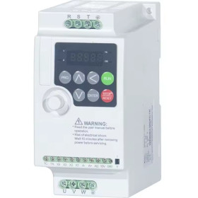
Frequency inverter, three-phase 380V, HSD3000, 4 kW
Robust solution for controlling the speed of three-phase motors in industrial applications such as pumps, fans, processing machines, and automated lines. 380V three-phase power supply and 4kW power, fine speed adjustment through 0-400Hz frequency. Offers 0-10V or 4-20mA analog control and RS485 Modbus communication for integration with PLC or SCADA. Includes electrical protections and DIN rail mounting.
Shipping by Thursday 22 October
Buying this product earns you 49.57 RON in loyalty points.

International fast shipping within EU. Free Shipping for orders above 100 EUR in most EU countries.

We ship from our stock within 24H

You earn points with every order, worth 5%.
The HSD3000 series frequency inverter is a robust and versatile solution for controlling the speed of three-phase motors, suitable for a wide range of industrial applications, including drilling, milling and woodworking machines, fans, assembly lines, packaging machines, mixers, pumps, water supply systems, and various automated equipment.
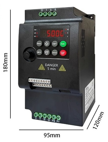
The 4KW version operates on a 380V three-phase input and provides an adjustable three-phase output voltage, with a frequency range from 0 to 500 Hz and a rated current of 9A, allowing fine motor speed adjustments according to application requirements. Its compact design, with dimensions of 83 x 168 x 180 mm and a weight of only 1.21 kg, makes it easy to integrate into electrical panels or spaces with limited room.
The device supports analog control via a 0-10V voltage signal or a 4-20mA current signal, as well as RS485 digital communication with Modbus protocol, making it compatible with SCADA systems, PLCs, and automation controllers (including Arduino with RS485 shield, STM32, ESP32, or other platforms with UART/RS485 interface). The built-in control panel, with dedicated buttons and a rotary knob for frequency adjustment, allows direct parameter setting and operation monitoring without additional equipment.
The system includes built-in protections against overcurrent, overvoltage, undervoltage, overheating, overload, and short circuit, ensuring the safety of both the equipment and the connected motor. The braking unit is built in, requiring only the connection of an external resistor. The supported operating temperature is between -10 and 40°C.
It features DIN rail mounting, which simplifies installation and allows quick mounting in standard electrical cabinets, without the need for additional fastening operations.
Specifications:
Power: 4 KW
Input voltage: 380 VAC three-phase (±15%)
Output voltage: 0 - 380 VAC adjustable three-phase
Output frequency: 0 - 500 Hz adjustable
Rated output current: 9 A
Control mode: V/F (voltage/frequency)
Carrier frequency: 1 - 15 kHz adjustable
Overload capacity: 150% for 60s, 180% for 3s
Analog control: 0-10V, 4-20mA
Communication: RS485 Modbus RTU
Protections: Overcurrent, overvoltage, undervoltage, overheating, overload, short circuit
Braking unit: built-in
Protection rating: IP20
Operating temperature: -10 ~ 40°C
Dimensions: 83 x 168 x 180 mm (W x H x D)
Weight: 1.21 kg
Pinout:
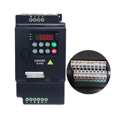
| Terminal | Description |
|---|---|
| PE (ground) | Protection, connected to ground |
| R / L1 | R phase input |
| S | S phase input |
| T / L2 | T phase input |
| U | Motor phase U output |
| V | Motor phase V output |
| W | Motor phase W output |
| PE (ground) | Protection, connected to motor housing |
| PB | External braking resistor connection |
| P+ | Positive DC bus terminal, for braking resistor |
| P- | Negative DC bus terminal |
| 24V | +24V output for control circuits and sensors |
| 10V | +10V output for external potentiometer. Recommended potentiometer resistance: 5–10 kΩ |
| AI | Configurable analog input: 0–10V or 4–20mA |
| VI | Voltage analog input: 0–10V |
| 0V / GND | Common ground for analog and digital signals |
| DI0 | Multifunction digital input 0 |
| DI1 | Multifunction digital input 1 |
| DI2 | Multifunction digital input 2 |
| DI3 | Multifunction digital input 3 |
| DO | Open-collector digital output. Mode selected by parameter F3-21 |
| TA | Relay contact |
| TC | Relay contact |
| NC | Not connected |
| A+ | Modbus, positive line |
| B- | Modbus, negative line |
| J11 | Connector for external keypad, optional |
Usage:
Mount the inverter on a vertical surface, in a ventilated panel, leaving free space on all sides for airflow and proper cooling (minimum 10 mm on the sides and 100 mm above/below).
Connect the three-phase power cable (380V) to the R, S, T terminals on the top side of the inverter.
Properly ground the upper PE terminal to the electrical panel grounding bar.
Connect the three-phase motor to the U, V, W terminals on the lower side of the inverter.
Connect the motor housing to the lower PE terminal of the inverter.
If the application requires quick stopping or braking, connect an external braking resistor between the PB and P+ terminals.
For simple start/stop control, connect a normally open contact between the 0V terminal and the DI0 terminal.
For analog speed control, connect a 5-10kΩ potentiometer with the wiper to AI, one end to 10V, and the other end to 0V.
For RS485 Modbus control (for example from a PLC, Arduino with RS485 shield, STM32 or ESP32), connect the A+ and B- lines to the RS485 bus and configure the address and communication speed from parameter group F8.
At first startup, access the menu with the PRG button, navigate with the ▲/▼ and >> keys, confirm with ENTER, and enter the motor parameters from group F4 (rated voltage, rated current, rated speed, rated frequency).
Check the motor rotation direction. If it is reversed, change parameter F0-02 or, with the power disconnected and after waiting at least 10 minutes, swap any two phases at terminals U, V, W.
Press the RUN button to start the motor and adjust the speed using the rotary knob, external potentiometer, or analog signal.
Dimension diagram:
- Input Voltage
- 380 V
- Input Voltage Type
- AC
- Output Voltage Type
- AC
- Model
- HSD3000
- Rated power
- 4 kW
- Number of phases
- 3
Produs destinat utilizarii in proiecte electronice, automatizari, prototipare, educatie si cercetare.
Produsul trebuie utilizat numai conform specificatiilor tehnice mentionate in descriere si/sau in documentatia produsului.
Avertismente generale de siguranta:
Nu utilizati produsul la tensiuni, curenti sau temperaturi peste valorile specificate.
Montajul si conectarea trebuie realizate de persoane cu cunostinte tehnice minime in domeniul electric/electronic.
Evitati scurtcircuitele, inversarea polaritatii si conectarea gresita a alimentarii.
Nu lasati produsul alimentat nesupravegheat in timpul testelor.
Produsul nu este jucarie si nu este destinat copiilor.
Pentru modulele electronice, se recomanda utilizarea in carcase, panouri sau montaje protejate, dupa caz.
Identificare produs:
Denumirea produsului, codul/SKU-ul si caracteristicile tehnice sunt mentionate in pagina produsului si/sau pe eticheta ambalajului.
Producator / Importator / Distribuitor:
Sigmanortec S.R.L.
Calea Bucuresti nr. 9, Targu Jiu, Gorj, Romania
E-mail: [email protected]
Website: www.sigmanortec.ro
Persoana responsabila in UE:
Sigmanortec S.R.L.
Calea Bucuresti nr. 9, Targu Jiu, Gorj, Romania
E-mail: [email protected]
Documentatie si siguranta:
Pentru informatii suplimentare, fise tehnice, declaratii de conformitate sau instructiuni, ne puteti contacta la [email protected].