

Product images are for informational purposes only and may vary slightly depending on the batch and supplier. Product specifications and prices may be subject to change without notice. We do our best to provide accurate and complete product specifications, but they may not be completely accurate. If you encounter any such situation, please let us know.
The product is intended for specialists and requires qualified and authorized personnel. The product does not include assembly/use instructions . Putting the product into operation by unqualified persons leads to the loss of the warranty according to the Terms and Conditions on the site.
The specified technical parameters (current, power, etc.) represent maximum allowable values under ideal operating conditions. For safe use and optimal lifespan, it is recommended to operate the product continuously at no more than 50% of the specified maximum values.
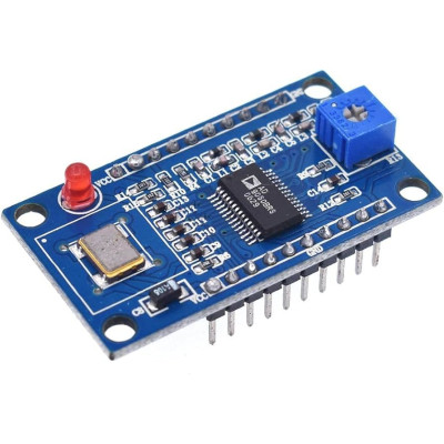
DDS generator module, AD9850, 0-40MHz, 3.3-5V
DDS generator for Arduino and other boards, ideal for RF testing, laboratory signals and prototyping, allows rapid frequency change through high-resolution digital control, generates sine 0-40MHz and square 0-1MHz, offers 2 sine outputs and 2 square outputs with adjustable duty cycle, operates at 3.3-5V and includes 125MHz active clock.
Shipping by Wednesday 16 September

International fast shipping within EU. Free Shipping for orders above 100 EUR in most EU countries.

We ship from our stock within 24H

You earn points with every order, worth 5%.
DDS (Direct Digital Synthesizer) module, compatible with Arduino and other development boards, which allows dividing the frequency of the system clock (clock) by programming a frequency control word, being able to quickly change the output frequency, thus generating the frequencies needed for various applications.
The module operates in the digital domain and offers significant advantages such as fast output frequency change and high frequency resolution.
The internal structure of the DDS includes three main components: the phase accumulator, the phase-amplitude conversion and the digital-to-analog converter (DAC).
The module can generate sine wave and square wave, having 2 outputs for sine wave and 2 outputs for square wave. the output frequency for this module is between 0 and 40MHz for the sine wave and between 0 and 1MHz for the square wave, with the possibility of adjusting the duty cycle through the integrated potentiometer.
Note
At frequencies between 20-30MHz, the harmonics become more and more pronounced, and the waveform becomes less clean.
Adjusting the variable resistor can alter the duty cycle of the square wave to suit specific requirements.
Specifications:
Supply voltage: 3.3 - 5VDC
Types of Generated Waves: Sine and Square
Sine Output Frequency: 0-40MHz
Square Output Frequency: 0-1MHz
Continuous Digital Output Current: 0.005A
DAC Output Current: 0.03A
Low Filter: 70MHz for SNR improvement
DAC: 10-bit
Frequency Control Word: 32-bit
Active Crystal: 125MHz
Input Reverse Protection: Yes
Dimensions: 45 x 30 x 15 mm
Pinouts:
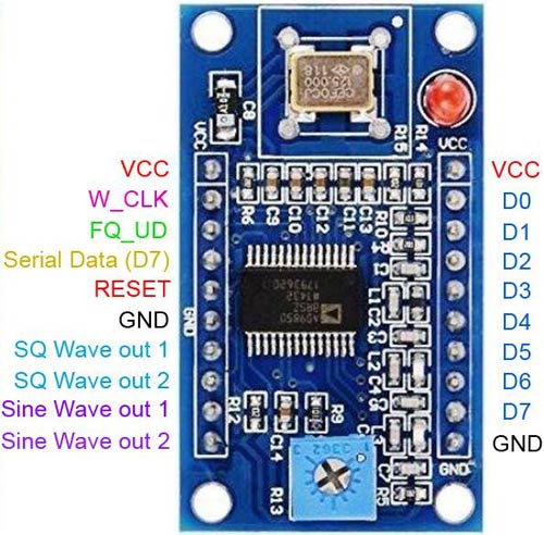
VCC : Power pin. It supports 3.3V or 5V voltage input.
GND : Ground Pin (GND).
W_CLK : Update Frequency. On the rising edge of this clock, DDS will update the frequency (or phase) loaded in the data input register, then reset the pointer to Word 0.
DATE : D7, Serial Loading.
RESET : Reset. Main reset function; when enabled (set high), it clears all registers (except the input register) and the DAC output will return to Cosine 0 after additional clock cycles.
D0–D7 : 8-Bit Data Input. This is the 8-bit data gate for iterative loading of the 32-bit control word for frequency and 8-bit for phase/28–25. D7 = MSB; D0 = LSB. D7 (Pin 25) also serves as the input pin for the 40-bit serial data word.
Square Wave Output 1 : The real output of the comparator.
Square Wave Output 2 : The complementary output of the comparator.
Sine Wave Output 1 : The current analog output of the DAC.
Sine Wave Output 2 : Complementary analog output of the DAC.
Example:
- Connect the AD9850 module to Arduino using the following pins:
W_CLK_PIN from the module to digital pin 13 on the Arduino .
FQ_UD_PIN to digital pin 8 .
RESET_PIN to digital pin 9 .
Make sure the module is also connected to the proper VCC and GND .
- Download and install the AD9850SPI library (byF4GOJ) in the Arduino IDE if it is not already installed.
Use the following test code (The DDS Module should now generate a 10 MHz wave, which is changed after 15 seconds to 10.0005 MHz.):
#it includes #it includes const int W_CLK_PIN = 13; const int FQ_UD_PIN = 8; const int RESET_PIN = 9; double freq = 10000000; // Desired frequency of 10 MHz double trimFreq = 124999500; // Calibration frequency for the DDS crystal int phase = 0; // Phase of the signal void setup(){ DDS.begin(W_CLK_PIN, FQ_UD_PIN, RESET_PIN); DDS.calibrate(trimFreq); } void loop(){ DDS.setfreq(freq, phase); delay(10000); // Hold the frequency for 10 seconds DDS.down(); // Stop the DDS signal delay(3000); // Wait 3 seconds DDS.up(); // Restart the DDS signal delay(2000); // Wait 2 seconds DDS.setfreq(freq + 500, phase); // Change the frequency delay(5000); // Hold the new frequency for 5 seconds DDS.down(); // Stops the DDS signal permanently while(1); // Loop stop } |
- tension
- AD
- Supply Voltage
- 3.3
- Maximum Input Voltage
- 5
Produs destinat utilizarii in proiecte electronice, automatizari, prototipare, educatie si cercetare.
Produsul trebuie utilizat numai conform specificatiilor tehnice mentionate in descriere si/sau in documentatia produsului.
Avertismente generale de siguranta:
Nu utilizati produsul la tensiuni, curenti sau temperaturi peste valorile specificate.
Montajul si conectarea trebuie realizate de persoane cu cunostinte tehnice minime in domeniul electric/electronic.
Evitati scurtcircuitele, inversarea polaritatii si conectarea gresita a alimentarii.
Nu lasati produsul alimentat nesupravegheat in timpul testelor.
Produsul nu este jucarie si nu este destinat copiilor.
Pentru modulele electronice, se recomanda utilizarea in carcase, panouri sau montaje protejate, dupa caz.
Identificare produs:
Denumirea produsului, codul/SKU-ul si caracteristicile tehnice sunt mentionate in pagina produsului si/sau pe eticheta ambalajului.
Producator / Importator / Distribuitor:
Sigmanortec S.R.L.
Calea Bucuresti nr. 9, Targu Jiu, Gorj, Romania
E-mail: [email protected]
Website: www.sigmanortec.ro
Persoana responsabila in UE:
Sigmanortec S.R.L.
Calea Bucuresti nr. 9, Targu Jiu, Gorj, Romania
E-mail: [email protected]
Documentatie si siguranta:
Pentru informatii suplimentare, fise tehnice, declaratii de conformitate sau instructiuni, ne puteti contacta la [email protected].